Ed Nisley's Blog: Shop notes, electronics, firmware, machinery, 3D printing, laser cuttery, and curiosities. Contents: 100% human thinking, 0% AI slop.
The previous iteration of GPS+voice interface boxes came from the Sherline CNC mill, with a considerable amount of huffing & puffing. I got the Thing-O-Matic to simplify that process…
The general idea is to build a box that clips onto the radio in place of the standard battery pack. External power comes into the box and goes directly to the radio’s battery contacts; this will pose a problem with the Wouxun KG-UV3D, because it wants 7.2 V rather than the stepped-up 9 V from the Li-Ion packs I’ve been using. I think a three-wire power cord is in order: +9 V for the interface, +7.2 V for the radio, and common.
The box also interfaces with the radio’s mic and speaker jacks. Last time around, I made a gluing fixture to keep the plugs in alignment while the epoxy cured around the plugs in the plate, but maybe I can simplify that with 3D printing. Plastic will be better in one respect: the shells of the two plugs must be electrically isolated.
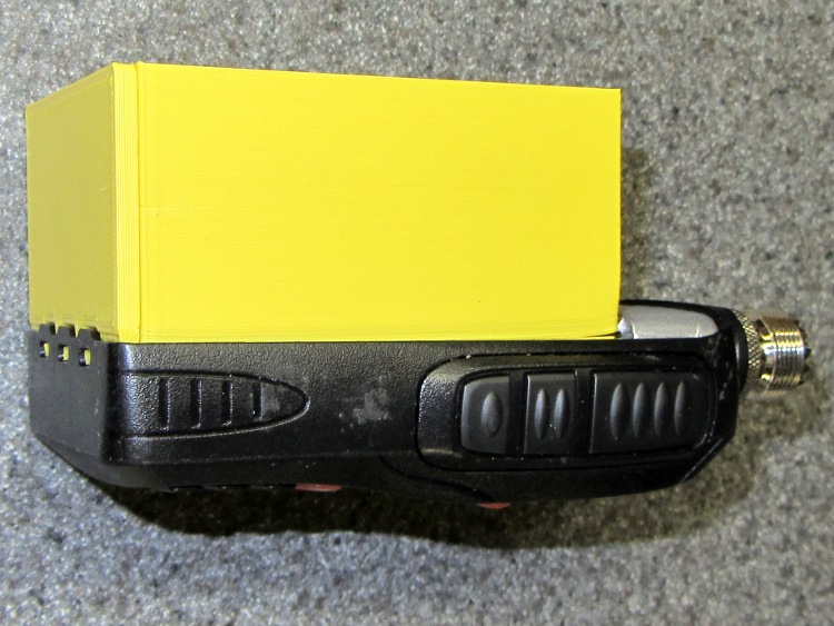
This first-pass (*) approximation shows the three tabs on the pack that engage the radio’s base:
KG-UV3D Interface Box prototype – right side
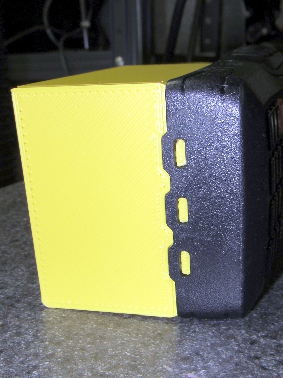
A detail of those tabs, as seen from the bottom:
KG-UV3D Interface Box prototype – end tabs
The ICOM IC-Z1A battery pack had a set of slip-in alignment features that held the pack on the radio, so two strips of tape sufficed to hold the interface box in place. Each Wouxun battery pack includes a spring-loaded latching mechanism that engages a pair of ramped tabs on the radio body that hold the pack against the spring-loaded battery contacts. That means I must come up with an actual latch of some sort to oppose the contact springs, but I haven’t figured that out yet.
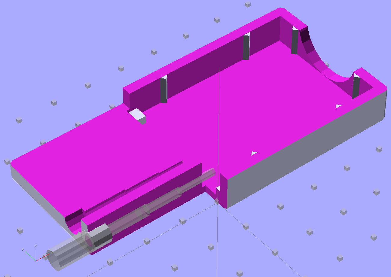
The solid model, with the plug mounting plate floating beside it, looks like this:
Case Solid Model – Tab End View – Fit
Tomorrow, the solid modeling…
* It’s actually the third printing of the bottom plate with the three tabs and the base plate with the battery contacts. That’s how I figured out the 0. 5% shrinkage thing.
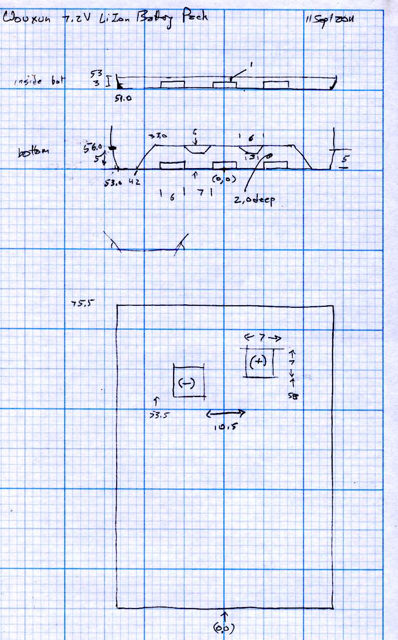
[Update: The sketch with the dimensions emerged from beneath a pile o’ stuff…]
It seems most of the stuff I build with my Thing-O-Matic involves small features and thin sections that bump hard against the minimum possible sizes. I’ve found that forcing critical solid model dimensions to be integer multiples of the the extrusion width or thickness stabilizes the whole idea→model→G-Code→object chain by encouraging Skeinforge to make the choices I prefer.
Or perhaps I’m just constraining my choices to make Skeinforge happiest. One can view reality in many ways…
Anyhow, my OpenSCAD programs tend to have these lines up near the top:
ThreadThick = 0.33;
ThreadWidth = 2.0 * ThreadThick;

function IntegerMultiple(Size,Unit) = Unit * ceil(Size / Unit);
The ThreadThick parameter matches the Skeinforge thread thickness parameter(s) and the 2.0 matches the w/t setting(s). Those correspond quite closely to the actual printed results, as tediously verified through many measurements. Throughout the rest of the OpenSCAD program, I compute the dimensions of key features using those sizes as building blocks.
The IntegerMultiple function returns the next higher multiple of the basic Unit that’s greater-than-or-equal-to the desired Size. Feeding in the thread thickness or width as the Unit ensures that the result will be an integer multiple of the smallest-possible dimension and won’t be smaller. The integer limit happens automagically, because the printer can’t lay down anything else, but a less-than-possible size can cause features to (unpredictably, in my experience) vanish without warning. This way your model reflects the printed reality and Skeinforge seems more likely to produce a predictable result.
So the parameter controlling the thickness of a flat sheet might look like:
PlateThick = IntegerMultiple(2.0,ThreadThick);
Given ThreadThick = 0.33, the sheet will be 7 layers thick = 2.31 mm. If the sheet must not exceed 2.0 mm, however, then you need a similar function with floor(), which may eradicate very small features.
This trick seems most useful for thin wall sections, because the wall width directly affects the fill:
Less than 1 thread width can’t be built
Exactly 1 thread width is the thinnest possible wall
Widths between 1 and 2 thread widths may be either, depending on surrounding features
Exactly 2 thread widths produces a nice wall
Widths between 2 and 3 thread widths can’t fill properly
Exactly 3 thread widths fills perfectly
Over 3 thread widths generally fill properly
So making the rim around a recessed lid become an integral number of thread widths, with a minimum width of 1.0 mm, looks like this:
LidMargin = IntegerMultiple(1.0,ThreadWidth);
With a 0.66 mm thread width, the nominal wall is 1.5 threads wide and could print as either 1 or 2 threads, depending on other factors. Rather than leave the results to chance, I force the solid model wall to be exactly 2 threads wide to make the printed result come out at 1.32 mm. Because I don’t care exactly how wide the lid margin is, as long as it’s at least one thread, that’s fine with me.
Generally, the values come from computations based on other dimensions, so quantizing the results keeps the printed result stable over small variations of those inputs.
If I ever get around to changing the nozzle to from 0.5 mm to 0.4 mm, I’ll probably change the thread dimensions to 0.25 mm x 0.5 mm (keeping the same 2.0 w/t ratio). A 1.0 mm wall would then still be exactly 2 threads wide and come out looking exactly the same, but with a total width of 1.00 mm.
That little Lenovo Q150 doesn’t include an optical drive and, mostly, I don’t need one, but sometimes it’s handy to boot from a CD. I picked up a used DVD burner that also fits my Dell E1405 laptop (should I need a spare) and a tiny USB laptop drive case from the usual eBay sources for a grand total of $17 delivered.
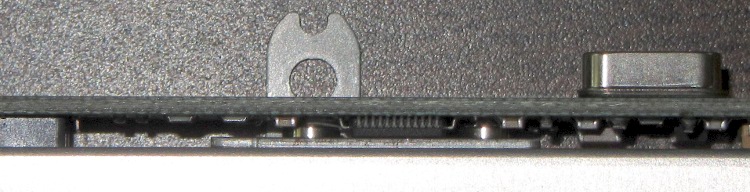
The drive had a mounting bracket on the back that obviously had to come off, because the bracket screws snuggled right in among the USB adapter electronics:
E1405 DVD drive bracket vs USB electronics
In fact, that flat tab with a hole would have clunked up against the back of the case and prevented it from sliding all the way in, but the screws also foiled Plan B: flip the bracket around so the tab goes under the drive where it couldn’t get lost if I needed it again.
So now the bracket & screws live in a little bag in the Box o’ USB Stuff.
The DVD drive works fine with just a single USB cable, although the case came with a power-only USB cable, so the latter also lives in the bag with the bracket. Maybe I’ll need it in the unlikely event I actually burn a DVD in that drive?
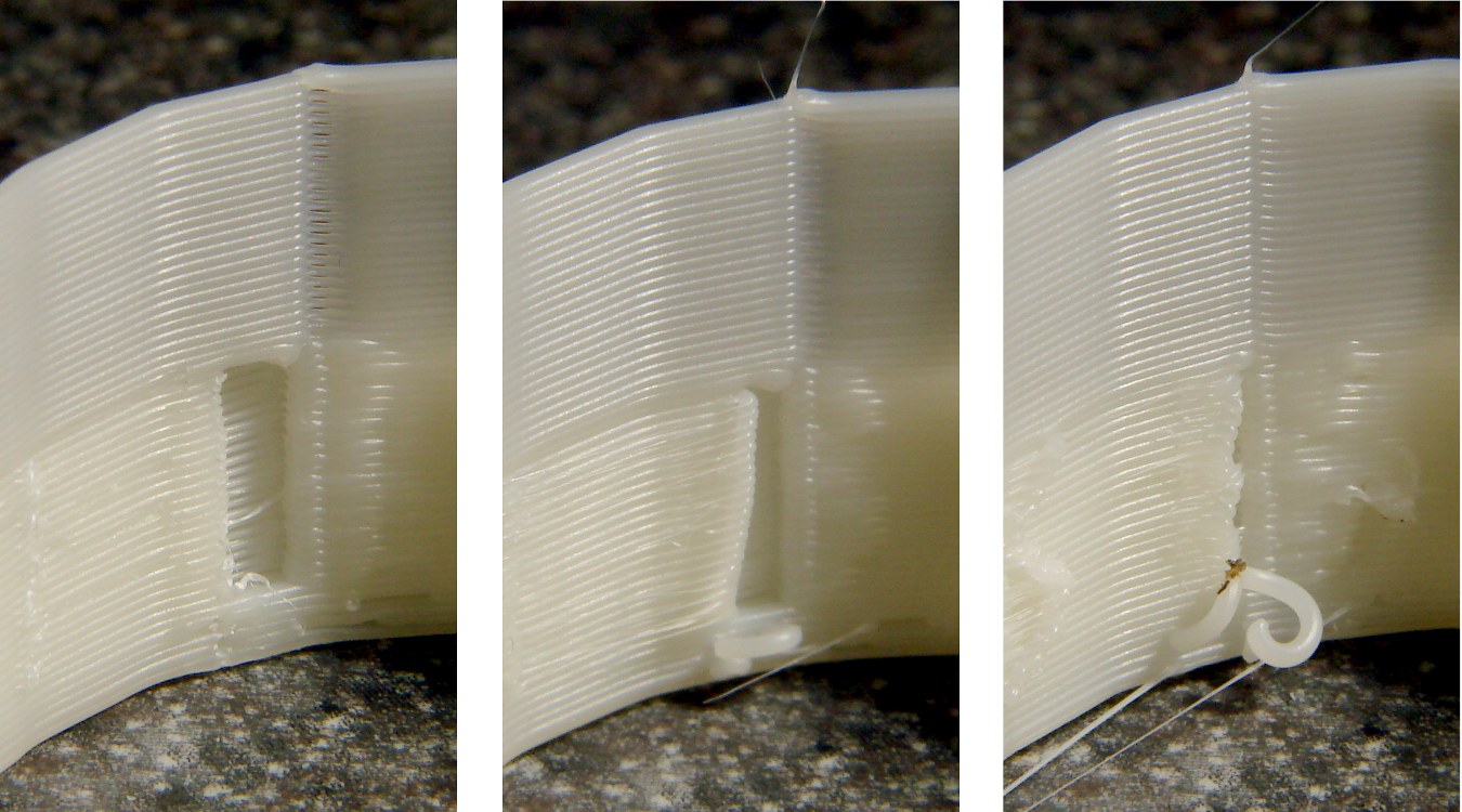
While cranking out some Tux Cookie Cutters, I varied the Reversal settings to see what effect they’d have on a single object with a smooth perimeter. I’d previously settled on 25 rpm for 125 ms with no early action, so this series tests three different times with early action turned on.
Position 1, where the perimeter threads join. Yes, I have Jitter activated and cranked up to something like 10, but it obviously has no effect on this object:
Position 1 – Reversal 125 100 50 – early
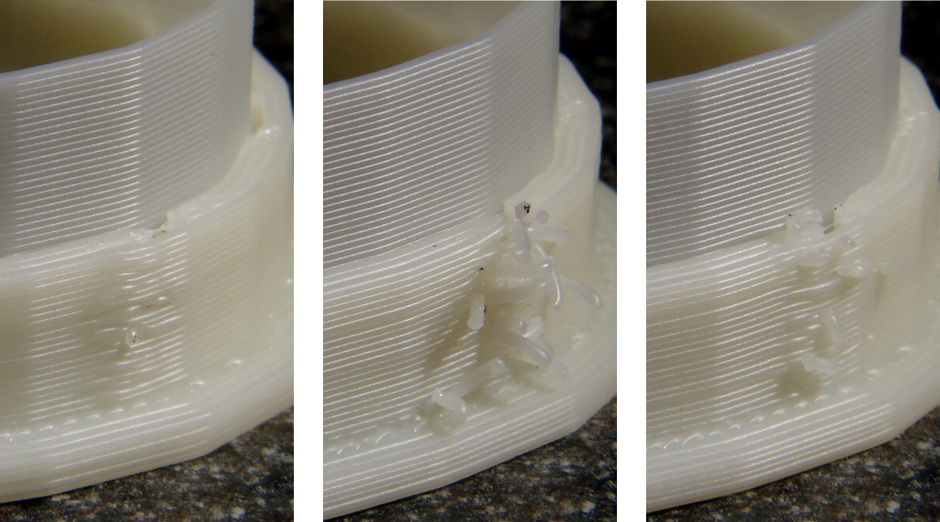
Position 2, where the nozzle enters from the outside to start a new thread. The snot hanging off the end makes for an ugly wad:
Position 2 – Reversal 125 100 50 – early
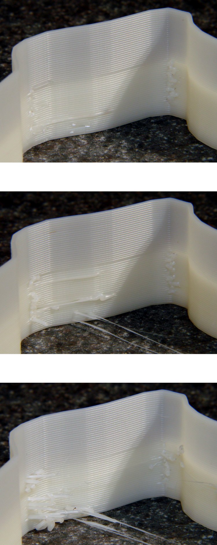
Position 3, another nozzle entry point:
Position 3 – Reversal 125 100 50 – early
Early Reversal action simply doesn’t work well. With retraction times sufficient to prevent drooling, stopping the extruder before the end of the thread produces unacceptable gaps and starting it before reaching the thread produces hanging snots when the nozzle passes over an existing wall.
Shorter retraction times produce strands all over the object, because the extruder still contains pressurized plastic and drools.
I’d previously discovered, although I didn’t write up, that unbalanced Reversal times didn’t provide any benefit: inhale and exhale times must be essentially equal to prevent either starving the first part of each thread or serious drooling. So there’s really only one degree of freedom: the total volume of plastic = rpm x duration.
Perhaps having separate early action times would help: adjust the shutdown and startup delay times independently of the total Reversal inhale/exhale time. Right now, those delays are simply the inhale/exhale times, evidently assuming clean cutoffs and startups, which obviously isn’t the case.
And, alas, the Reversal Threshold bug remains unfixed, so you (well, I) can’t tell Reversal to not operate across short motions like the end of one thread and the not-quite-adjacent start of the next.
In the process of adapting my HT GPS interface to a Wouxun KG-UV3D radio, I printed some trial-fit pieces that consistently came out a little short. A bit of division showed that the larger pieces tended to be small in the X & Y axes by about 0.5%. This makes no difference for most 3D printed objects, but in this case the pieces must match up precisely with the radio’s existing battery interface layout. Half a percent matters a lot across a 75 mm part.
The advice found with most calibration pieces seems to boil down to fudging the printer’s steps/mm setting to make the answer come out right. The default Thing-O-Matic calibration (in machines/thingomatic.xml, wherever that’s hidden in your installation) looks like this:
You will, of course, have twiddled the maxfeedrate, homingfeedrate, and maybe even the comments to make the answers work on your machine.
Nophead slapped me upside the head when I made the same mistake that produced the stock stepspermm values: the pulley moves the belt by a fixed number of teeth on each revolution, so you just multiply by the belt tooth pitch to find the distance per revolution. Divide that into the number of (micro)steps per revolution and you get the exact stepspermm value. The stock MBI pulleys have 17 teeth and the belt has a 2 mm tooth pitch, so:
47.05882 step/mm = 1600 step / (17 * 2 mm)
That differs from the stock value by not very much at all:
0.999766 = 47.05882 / 47.069852
Given that these steppers aren’t losing steps (don’t start with me, you know how I get), I’m quite confident that the X and Y stages move by exactly the commanded distance every time.
The money quote is that ABS shrinks just about exactly 0.5% as it cools. That’s modulo the starting temperature, the molding process, and so forth and so on, but it’s a pretty nice match.
Therefore, fudging the printer’s scale isn’t appropriate, because that affects everything you might do with it. Such as, for example, the initial homing sequence, which depends on fairly precise locations that must match up with reality and have no shrinkage problems whatsoever.
Skeinforge’s Scale plugin applies a factor to the object, so that’s (probably) a more appropriate location for this adjustment. The myriad SF settings get broken down by Craft (extrusion, milling, whatever) and material (ABS, PLA, whatever), so if you can keep all that straight, then you can apply the appropriate Scale for each process and material.
The Scale doc may seem a tad sparse, but the plugin does have separate settings for the XY plane and the Z height. The latter (probably) doesn’t need scaling, because the nozzle height sets the actual extrusion level; the top layer or two will stretch to make the vertical size come out right as the object cools while it’s a-building.
I’ll toss a 1.005 scale factor into the XY mix and see what horrors that unleashes by way of unintended consequences.
More on the radio interface & suchlike in a while…
Having twicefailed to make music-wire springs work, I rummaged around in the Big Box o’ Small Springs with more diligence and unearthed a pair of coil compression springs that exactly match the pin ferrule OD. Twiddling the solid model produced this longer & flatter version with in-line springs and cylindrical plugs holding them in place:
NB-5L Holder – Coil spring – solid model
A closeup of the pin arrangement, which now looks very clean and easy to build:
NB-5L Holder – Coil spring – detail
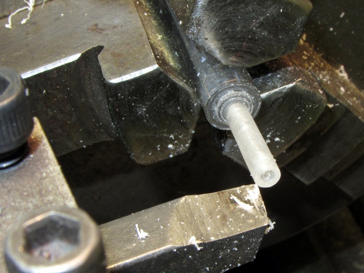
The OpenSCAD code will print out a quartet of plugs (pick the best two), but having thought of that too late, I turned a pair from a random acrylic rod:
Turning spring plugs
I did remember to solder the wires before assembling the pins this time…
Pin assemblies
Because the pins now index on their shoulder with the springs at partial extension, I set the drills into the pin vice vise[Update: One can probably be arrested for pin vice] to produce depths displayed by the OpenSCAD program before reaming out the printed holes:
Then glue the pin plugs into the holder and the flat lid atop the case to capture the battery, clamping everything to the corner of the Sherline’s countertop:
Gluing pin assemblies
And it Just Worked: nice travel between the limits, smooth operation, it’s the way I should have done it from the beginning*. You knew that all along, right?
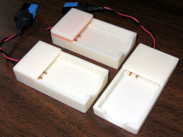
Here are the three NB-5L Battery Holder versions, all snuggled up together. The longer and flatter coil-spring version sits on the right: