Ed Nisley's Blog: Shop notes, electronics, firmware, machinery, 3D printing, laser cuttery, and curiosities. Contents: 100% human thinking, 0% AI slop.
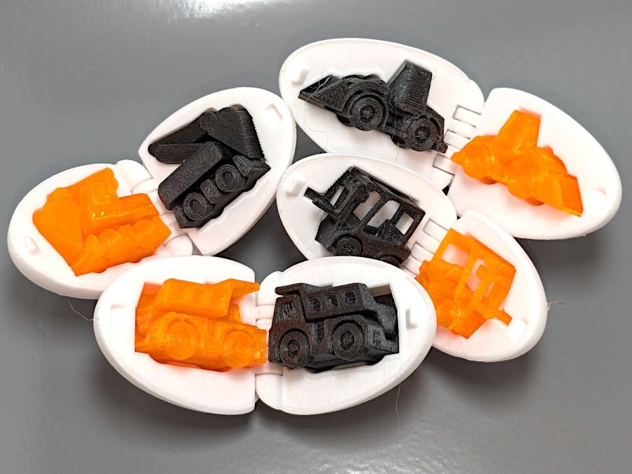
These cute little toys serve as 3D printer torture tests:
Surprise Eggs
Obviously, each egg can hold only one of those toys, but I had to run them off in both retina-burn orange PETG and black PETG-CF for comparison.
These Surprise Egg models came from Thingiverse, but they’re also available on Printables. You’ll find many more, of course, at a variety of scales, with these on the small end.
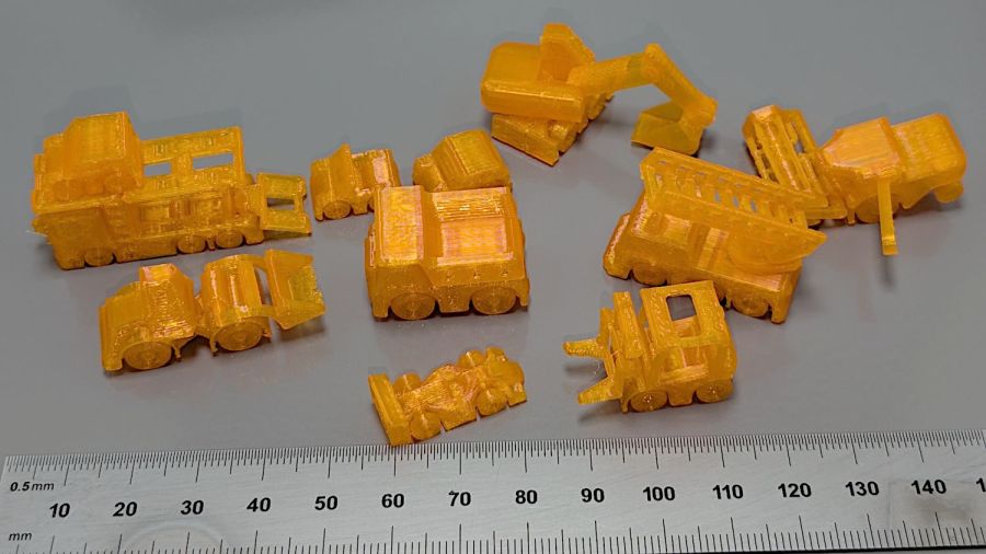
The white eggs print with no difficulty at all, as does most of the equipment contained within:
Surprise Eggs – contents – orange PETG
Most moving parts require careful back-and-forth movement to break them free, but they’re surprisingly functional. The PETG-CF, printed with an Extrusion Multiplier = 0.8, looks better, although the moving parts were more firmly stuck together.
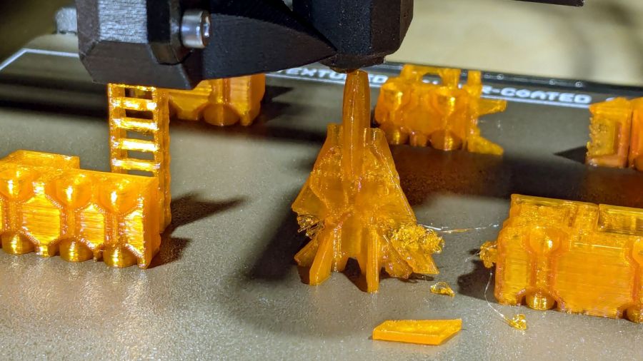
Not all of the equipment came out perfectly:
Surprise Eggs – contents on platform
Even without any special preparation, the MK4 didn’t have much trouble. If you were doing those for real, you could add stickum to the sheet or switch to a sheet with absurdly high PETG griptivity.
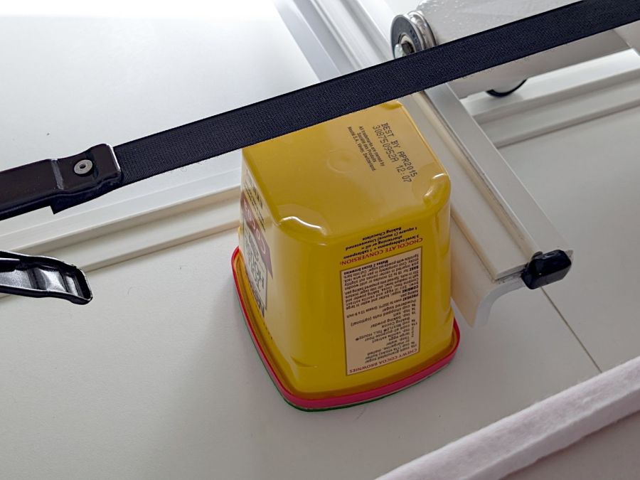
Although I devoted considerable attention to leveling & shimming the table under Mary’s HQ Sixteen, the machine rolls on ball bearing wheels atop (relatively) smooth plastic tracks. Parked at a few spots along the dozen feet of table, the machine will slowly and quietly roll away. This calls for some sort of parking brake, but until inspiration strikes, a simple anchor will suffice:
HQ Sixteen – anchor
It’s a cocoa container chosen from (one of) my Boxes o’ Containers, with a husky chunk of steel atop some very sticky double-sided foam tape inside the red lid.
You can see one of the ball bearing wheel just above the strap applying tension to the practice quilt out of view on the left. The thing that looks like a wheel just under the strap is an encoder for the stitch regulator that we haven’t connected yet.
To prevent the machine from simply bulldozing the container along with it, the lid sits on a sheet of EVA craft foam stuck to a sheet of rigid foam board (with adhesive on both sides).
Scan the lid:
Container lid scan
Select all the red pixels, do a little cleanup, turn it into a binary mask:
Container lid mask
Import it into LightBurn, trace the perimeter, do some curve optimization / smoothing, duplicate the outline, set one to cut EVA foam and the other to cut adhesive board, and Fire The Laser.
Elapsed time: about fifteen minutes from realizing what was needed to plunking the anchor in place.
I briefly considered a full-frontal laser-cut finger-jointed box for the weight, but … Mary’s not a big fan of that campfire smell, particularly in a room dedicated to the Fiber Arts.
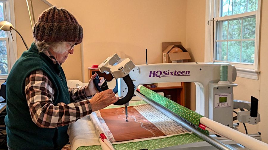
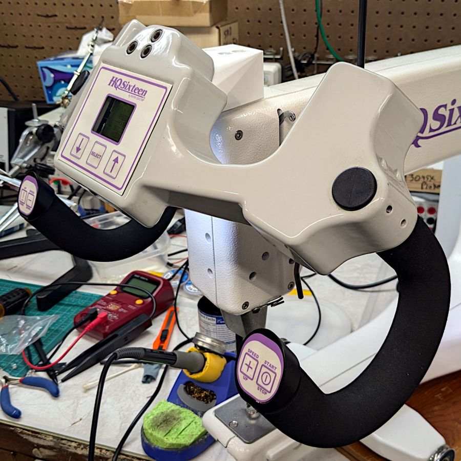
So as to not bury the lede, I remounted the front handlebar unit of Mary’s Handi-Quilter HQ Sixteen long-arm sewing machine so she can see the control panel with its small LCD:
HQ Sixteen – remounted handlebars in use
The new and old white LEDs produce distinctly different colors and intensities on the practice quilt fabric.
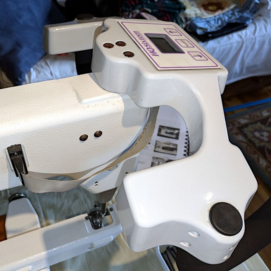
The original HQ Sixteen design bolted squarely atop the arm:
HQ Sixteen – original front handlebar mount
The control surface is, admittedly, angled slightly forward, but Mary was unable to see the lower few lines of the LCD without standing on tiptoe.
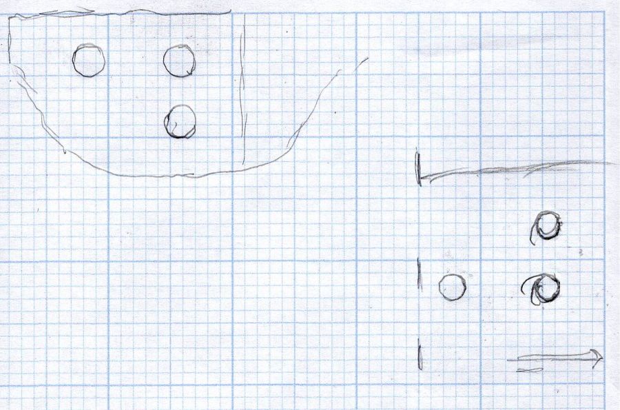
Begin with a crude tracing of the mating surfaces:
Front handlebar base tracings
Import the image into Inkscape and lay some shapes on it:
Front handlebar base layout – Inkscape
Import the SVG into LightBurn and cut templates to verify the hole positions:
HQ Sixteen – handlebar bolt templates
Obviously that took more than one try.
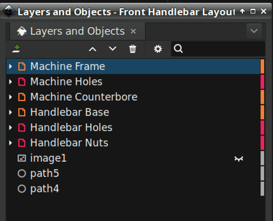
Rationalize the outlines, clean things up, and organize the shapes into useful named layers:
Front handlebar base layout – Inkscape layers
Save as an Inkscape SVG, import into OpenSCAD, and extrude the layers defining all those shapes into a solid model:
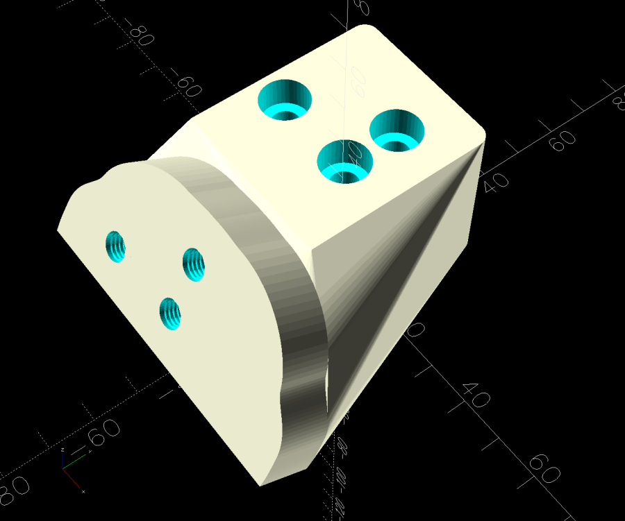
Handlebar Base Mount – solid model
That’s the most recent iteration; earlier ones appear in various pix.
I had intended to use either square nuts or heat-set inserts, but it turned out to be easier to just slam BOSL2 threaded nuts into the front plate and be done with it:
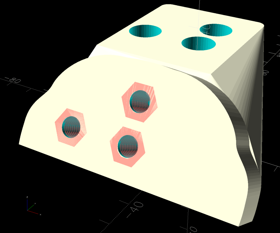
Handlebar Base Mount – solid model – hex nuts
The trick is to sink the nuts around a hole sized slightly larger than the screw’s nominal diameter, letting the threads fill empty space.
The handlebar base is mounted symmetrically along the machine arm centerline aligned with the two screws on the right. The rear block is offset to the left to clear the machine cover on the right, so the hull() wrapped around the two looks weird.
The front plate stands proud of the rest by dint of incorporating only a small slice of its back face into the hull() filling the gaps between the two. It’s not particularly stylin’, but it’s pretty close.
Finding the correct angle for the front plate required a couple of iterations, but they all built successfully:
HQ Sixteen – handlebar mount – on platform
Putting the threaded holes vertical created nicely formed threads that accepted the screws without hassle.
The block screws firmly to the arm and the handlebar unit screws to the block:
HQ Sixteen – remounted handlebars – side
The display now faces front:
HQ Sixteen – remounted handlebars – front
I eventually replaced those black oxide screws with shiny stainless ones, just for pretty.
The nine LEDs under the display now do a great job of lighting up the front of the machine’s arm, rather than the fabric at the needle, but fixing that will be a whole ‘nother project.
The handlebar grips with their control buttons now tilt at a somewhat inconvenient angle, which is also a whole ‘nother project.
Early reports from the user community are overwhelmingly positive.
The OpenSCAD source code and the SVG layout as a GitHub Gist:
This file contains hidden or bidirectional Unicode text that may be interpreted or compiled differently than what appears below. To review, open the file in an editor that reveals hidden Unicode characters.
Learn more about bidirectional Unicode characters
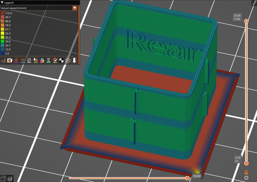
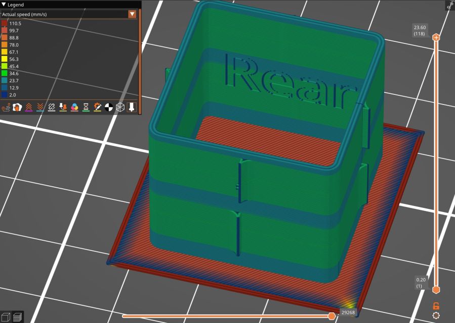
Loading the STL into PrusaSlicer, adding a text label to remind me which way it printed, then slicing with my PETG-CF profile shows the “Actual Speed”, which seems to take acceleration into consideration:
PrusaSlicer preview – actual speed
The colors in the legend don’t quite match the colors on the model, but the greenish layers with the jolts trundle along in the mid-20 mm/s range and the blue-ish straight-through layers at 30-ish mm/s.
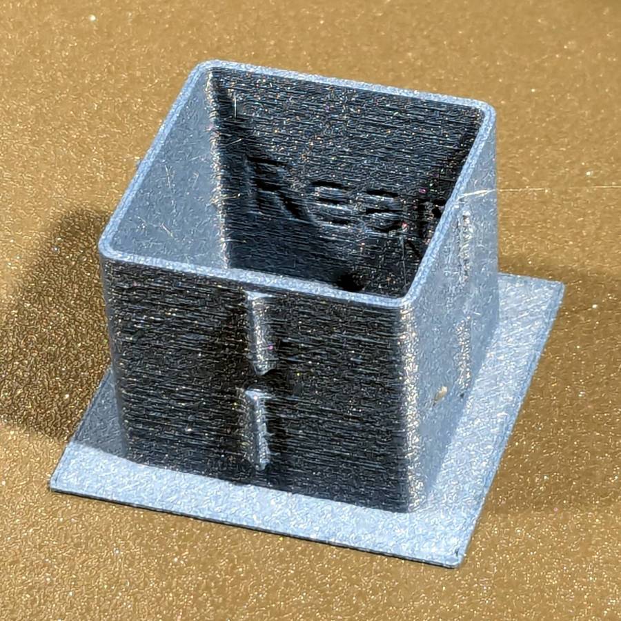
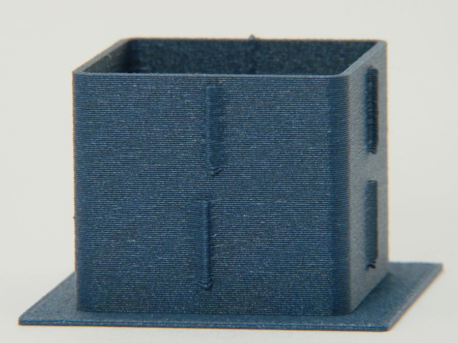
Eryone PETG-CF has a somewhat fuzzy appearance that seems not characteristic of other brands, so I’ll try something else when these spools run out:
MK4 Resonance Test Box – overview
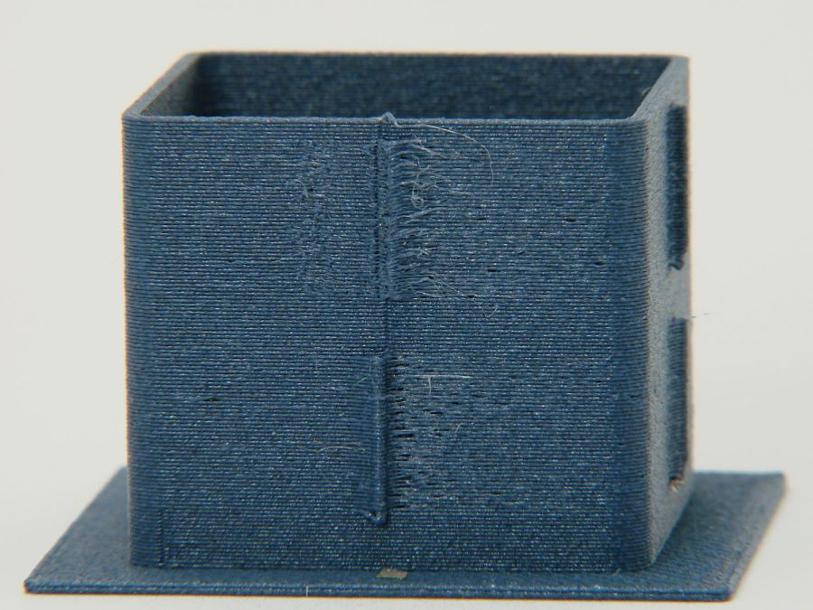
The right side of the box (as oriented on the platform) got all the layer retractions and came out festooned with PETG hairs:
MK4 Resonance Test Box – right side
You can check my labels by tracking the small retraction zit sticking up from the top layer; I got it wrong the first time. Open the images in a new tab to see more pixels.
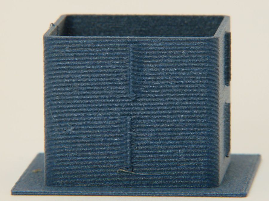
The front:
MK4 Resonance Test Box – front side
The left:
MK4 Resonance Test Box – left side
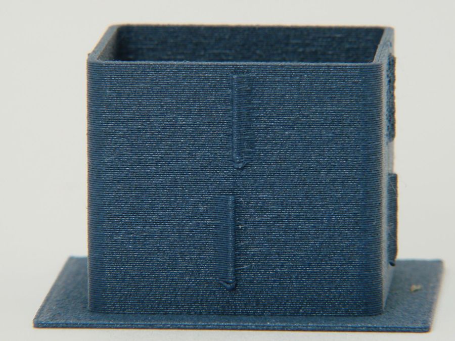
And the rear:
MK4 Resonance Test Box – rear side
You can barely see the shadow of the “Rear” text on the surface, even though the wall is two threads thick and the text is indented by 0.2 mm, about half the thread width.
As far as I can tell, the MK4 Input Shaper compensation does a great job of suppressing resonance or wobble in all directions.
Mary is at least the third owner of a steel rack, originally intended to hold packages of retail stuff, which now holds (much of) her collection of quilting rulers:
Quilting Ruler Rack Base – overview
Obviously, it was never intended to hold heavy acrylic sheets, but it worked surprisingly well, right up to the point where too many of the rulers collected on two adjacent columns of pegs and overbalanced the whole affair atop her while she attempted to remove a ruler.
Subsequent accident recreation showed the rack toppled when the weight of the rulers on the two adjacent columns of hooks moved the center of mass outward, just inside the line between those feet, whereupon the slightest tug on a ruler pulled it over.
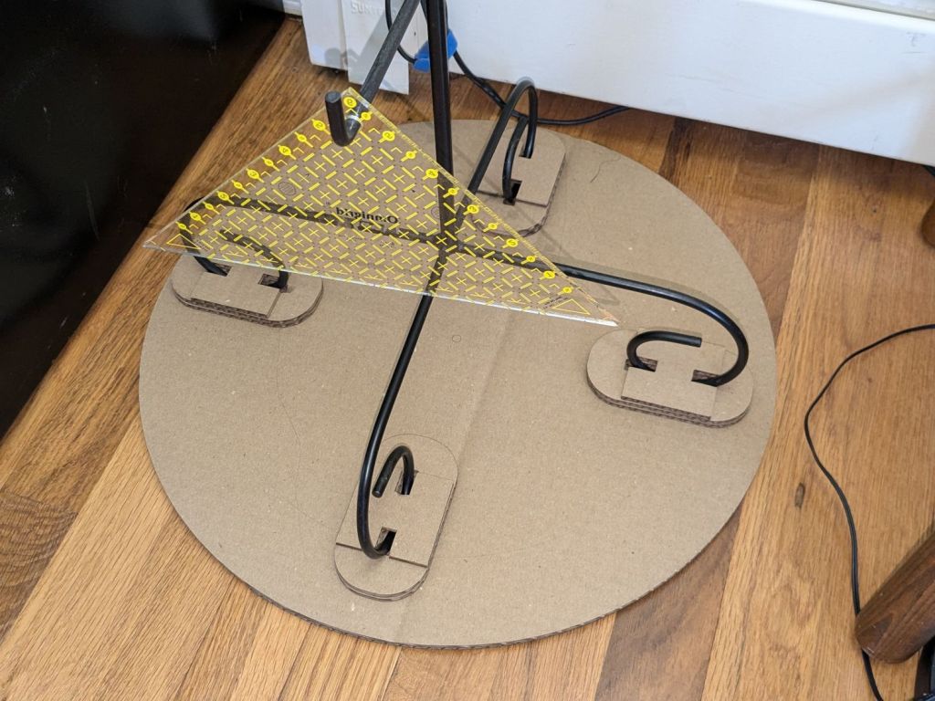
Measurements revealed the four legs do not sit on a square contact patch, are not parallel to the radii from the center point, and are not uniformly distant from the center. Rather than committing to a finished product, I made a cardboard prototype to verify a bigger base would solve the problem and I could capture all those feet.
You don’t have such a rack, so the exact dimensions don’t matter, but the LightBurn layout looks like this:
Quilting Ruler Rack Base
The disk is two cross-laid sheets for stiffness, with marks burned on the top to help align the feet more-or-less around the center point.
The oblong rings fit around the feet to capture them, so cut eight or twelve to make four stacks a bit taller than the wire diameter.
The H shape then glues atop the rings to hold the feet in place. They’re not removable, but a razor knife will eventually solve that problem.
I slobbered hot melt glue across the cardboard disks to hold them together, glued and aligned the rings where the feet dented the disks, stood the rack in the rings, and glued the H plates.
About an hour elapsed from the sound of the crash to the rack once again standing quietly beside the fabric cabinets.
We’ll run this for a while and eventually replace it with a plywood disk and screwed-in-place clamps for the feet, which will surely call for wood surface preparation / stain / seal treatment.
The Prusa belt tension guide pretty much explains that subject, with their Belt Tuner making up for my utter tone deafness. FWIW, if the Belt Tuner produces inconsistent results differing by an octave, either up or down from the correct value, the belt is way too loose: give the axis belt tension screw a turn or two to drag the results into the right time zone, then fine-tune from there.
While it is possible to reach both tensioning screws without too much trouble, they’re definitely not convenient.
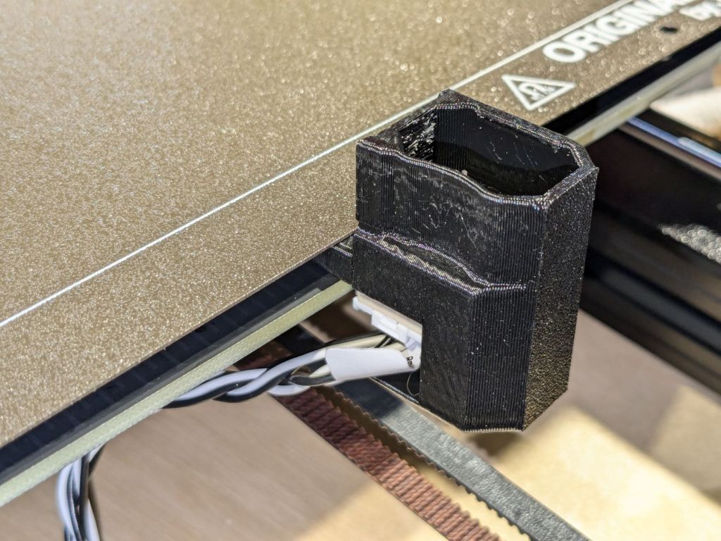
The accelerometer fits on the hot end:
Prusa MK4 Accelerometer – on hot end
Then under the steel sheet, where it’s clamped by the platform magnets:
Prusa MK4 Accelerometer – on platform
The MK4 firmware measures the resonant frequencies while prompting you to put the accelerometer in the proper locations, then computes the best shaper values.
For reference, the stock OEM values:
X = MZV 50 Hz
Y = MZV 40 Hz
Just after I got the accelerometer and without doing anything to prep the MK4, these results popped out:
X = MZV 56 Hz
Y = MZV 42 Hz
Now, with bling and properly tensioned belts:
X = MZV 59 Hz
Y = MZV 45 Hz
The most recent values were also the most stable, once again pointing out the value of careful assembly and maintenance.
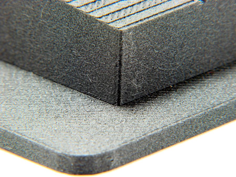
With that in mind, though, I built the laser ramp focus fixture shortly after doing the first recalibration and it has no visible ripples on any of its walls:
Ramp Test Fixture – corner detail
That’s a square corner perpendicular to the sloped top surface at the default 45 mm/s. It’s not as difficult a test as some you’ll see, but it suffices for my simple needs. The MK4 definitely behaves better around corners than the Makergear M2.
Although essentially all kitchens feature a microwave over the stove, essentially all women have difficulty reaching it. As a result, our kitchen has two microwaves: the built-in Samsung over the stove and our trusty Sears Kenmore on the counter.
We’ve had it for a while:
Sears Microwave – data plate
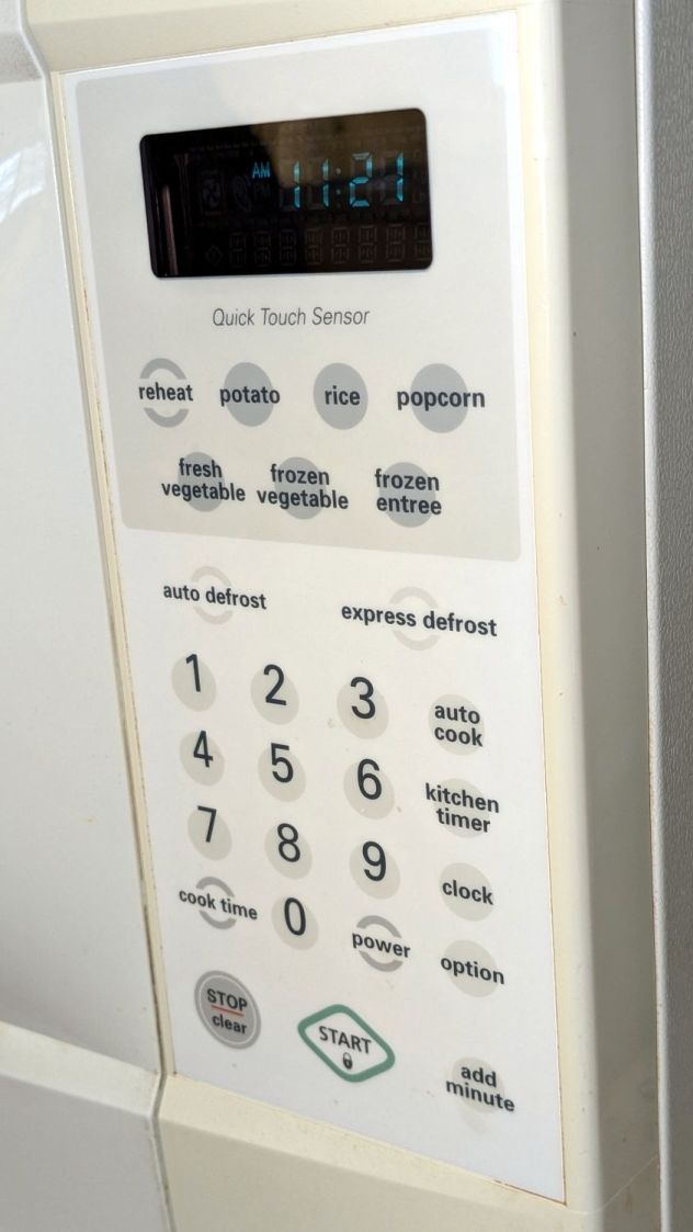
Apart from the turntable rollers, it’s been utterly reliable for the last two decades, until the Start button stopped working:
Sears Microwave – control panel
The membrane switch panel seems to be in good shape, with no cracks in the plastic surface. Only the Start button failed, which suggested the switch contact pad had failed and ruled out broken matrix traces on the flexible circuitry.
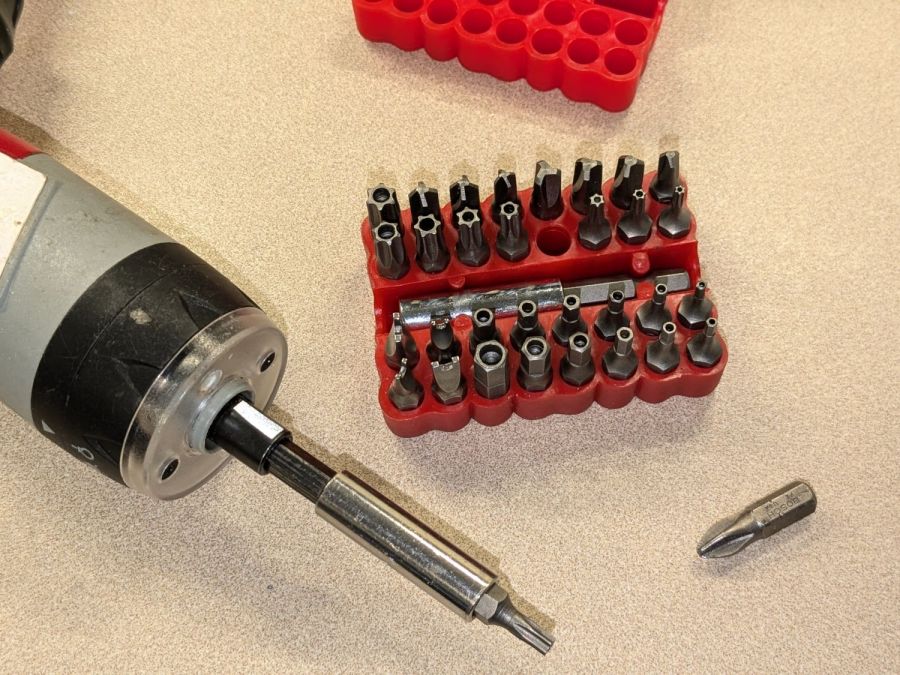
Back in the day, they kept casual tinkerers out of the dangerous interior:
Sears Microwave – Torx security screw
That would not be me:
Sears Microwave – security bit set
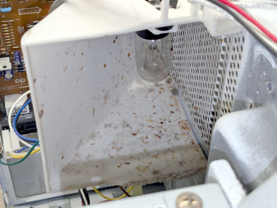
Over the course of two decades, an occasional food explosion produces a surprising amount of debris:
Sears Microwave – exhaust vent spatter
Go ahead, I dare you, show us your microwave exhaust vent.
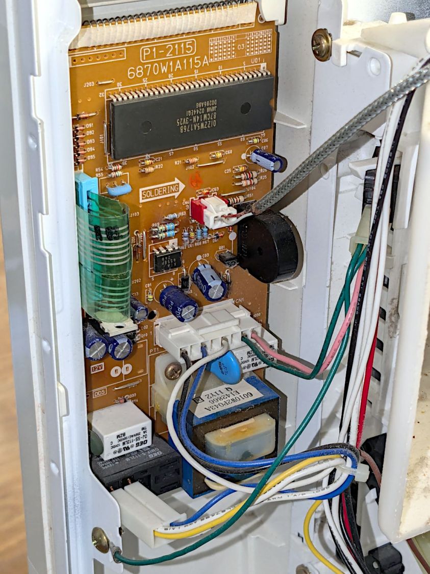
The control panel circuit board & wiring looks like this:
Sears Microwave – control board – in place
Unplugging all the connectors proceeds as you’d expect, whereupon a single screw (out of sight to the top) releases the control assembly and pulling the whole thing upward gets it out of the cabinet:
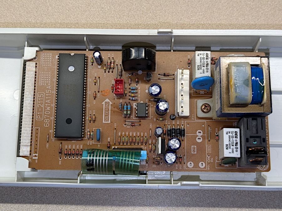
Sears Microwave – control board
The capacitors show no signs of The Plague, but those resistors near the optoisolator (?) in the middle have a suspicious thermal plume.
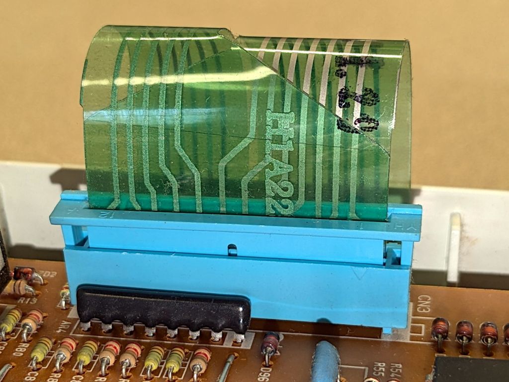
The ribbon cable from the control surface goes into a connector with the usual locking collar:
Sears Microwave – control panel cable connector
The cable also has cutouts latching into tabs molded into the collar:
Sears Microwave – control panel ribbon cable – locking tabs
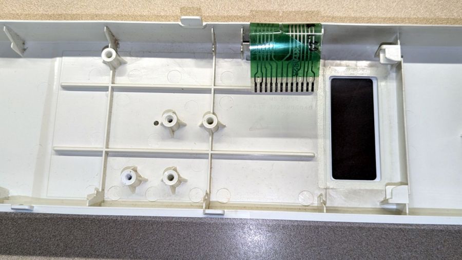
Removing two screws at the transformer releases the PCB:
Sears Microwave – control panel interior
Which promptly slammed the whole repair mission to a dead stop: with the entire membrane switch assembly glued to the front of the plastic shell, there is no way to get to the Start switch. Trying to peel the membrane off will most certainly destroy it.
Because all the other functions still worked, including the Add Minute button, we figured we can eke out a few more years before something else fails or the lack of one button gets intolerably annoying.
I reassembled everything in reverse order, plugged it in, and, while setting the clock, discovered the Start button once again worked perfectly.
It’s a classic laying-on of hands repair: take something apart, replace nothing, reassemble, and it works!
If the Start button is not part of the overall switch matrix, with a separate conductor through the ribbon cable, un- and re- plugging would be enough to restore a flaky contact. We’ll never know the rest of the story, although with this post as a reminder, maybe I can remember to tear the matrix apart when we scrap it out.


