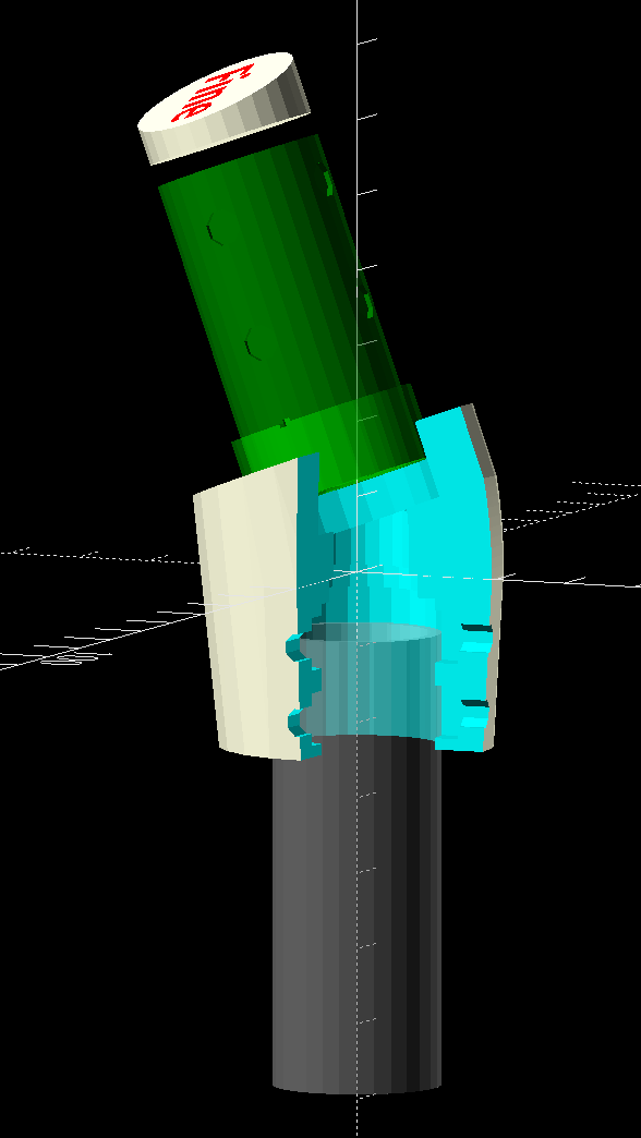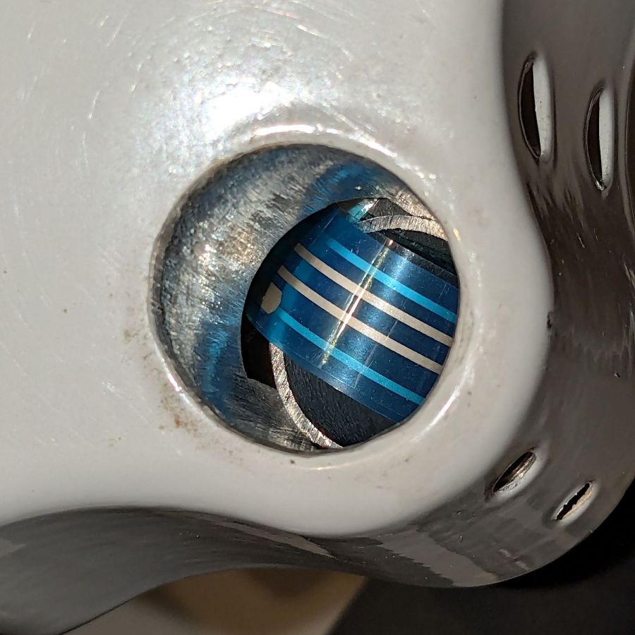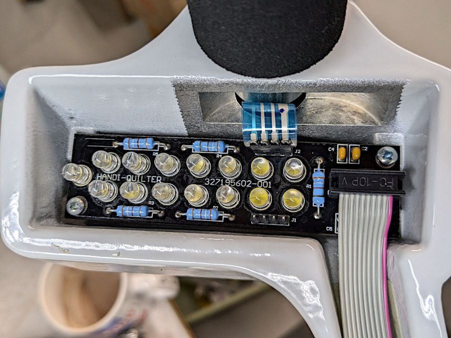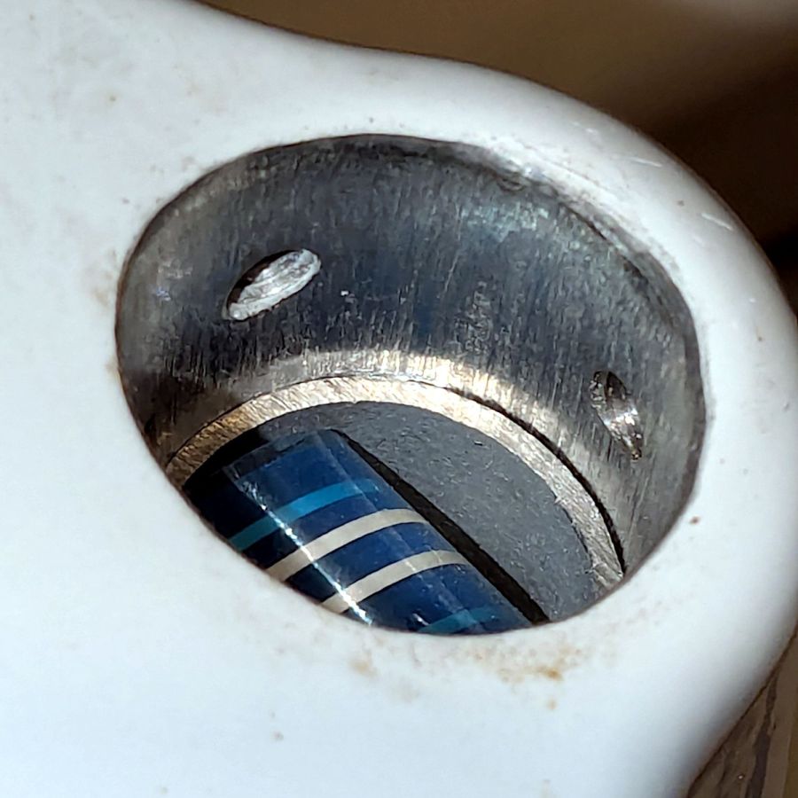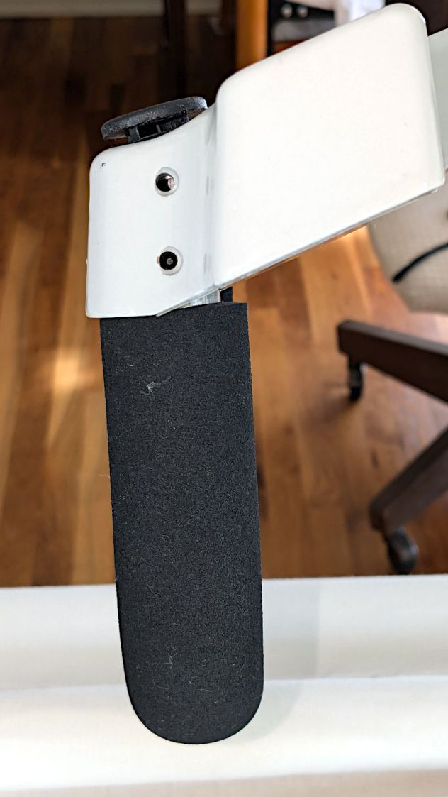
The stock Handi-Quilter HQ Sixteen has serviceable black rubber caps covering the holes for the grips:
Because we live in the future, I can do better than that:
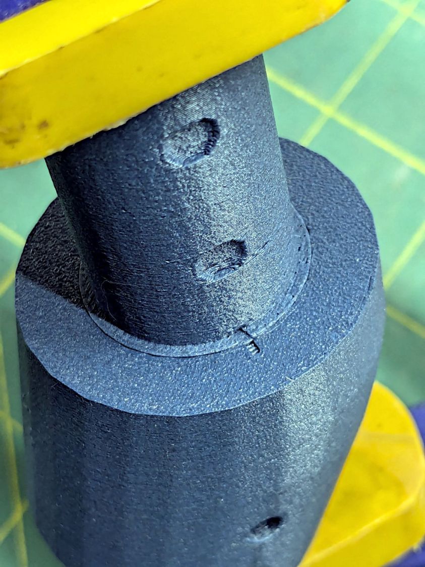
In truth, the plastic grip plug now sticks up into the hole just beyond the top setscrews, leaving not enough room for the black plugs, so I had to make new covers.
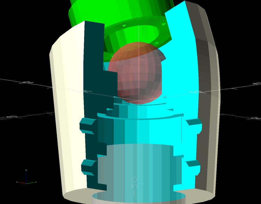
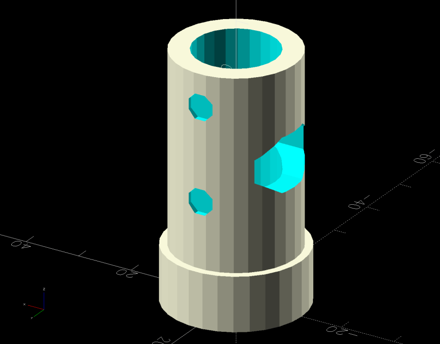
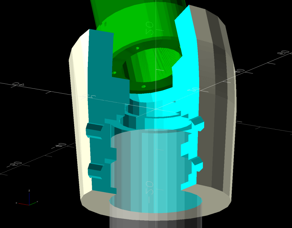
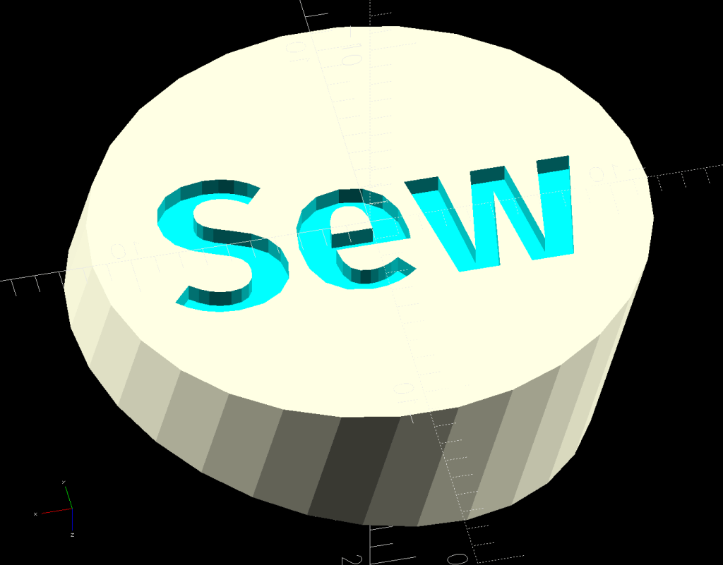
They’re a multi-material print using white PETG to kinda-sorta match the machine and blue PETG-CF to match the other plastic parts. The colors in the solid model just distinguish the two materials:
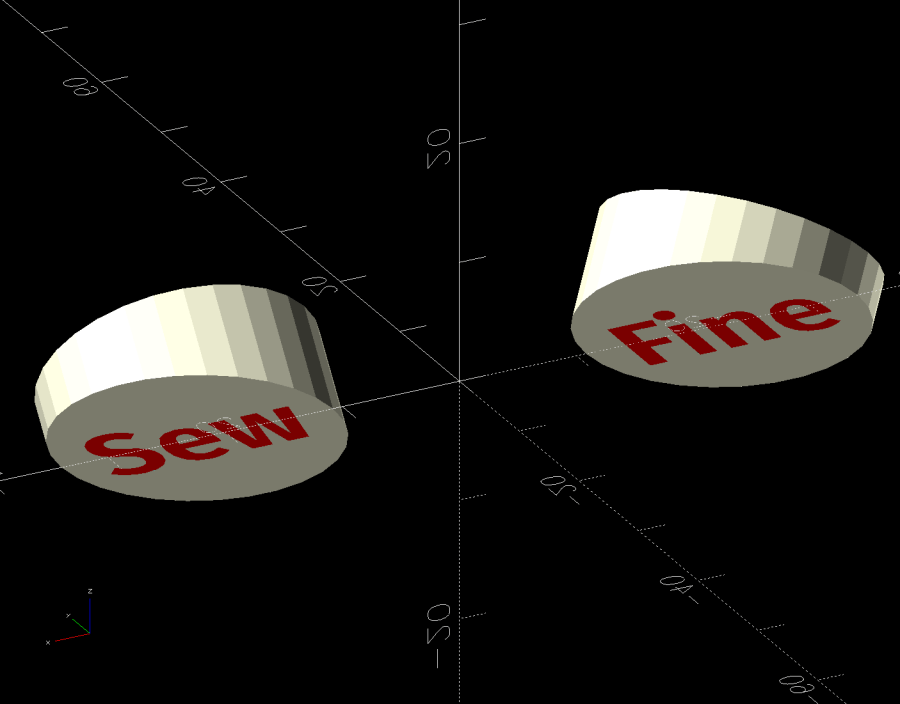
The white covers have recesses exactly fitting the text:

In some cases that’s not needed, but I’m unsure how PrusaSlicer knows what I intend and chopping the text out was easy, so that’s how I did it.
I did not realize applying a transformation, like translate() or BOSL2’s syntactic sugar left(), to both the cover and the text implicitly joins them into a single “object”, so the slicer can’t distinguish them as separate materials. As a result, the OpenSCAD code must move the pieces separately:
if (Layout == "Covers") {
     left(Plug[OD]) GripCover(LEFT,"Cover");
     left(Plug[OD]) GripCover(LEFT,"Text");

     right(Plug[OD]) GripCover(RIGHT,"Cover");
     right(Plug[OD]) GripCover(RIGHT,"Text");
}
Which is awkward, but not insurmountable.
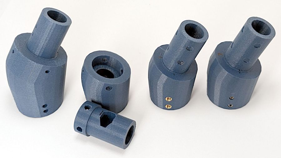
Export the model as a 3mf file, import it into PrusaSlicer, and you get separate objects for the cover and the text. Assign different materials and slice to produce a multi-material result, with the Wipe Tower in the background:
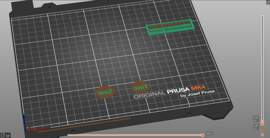
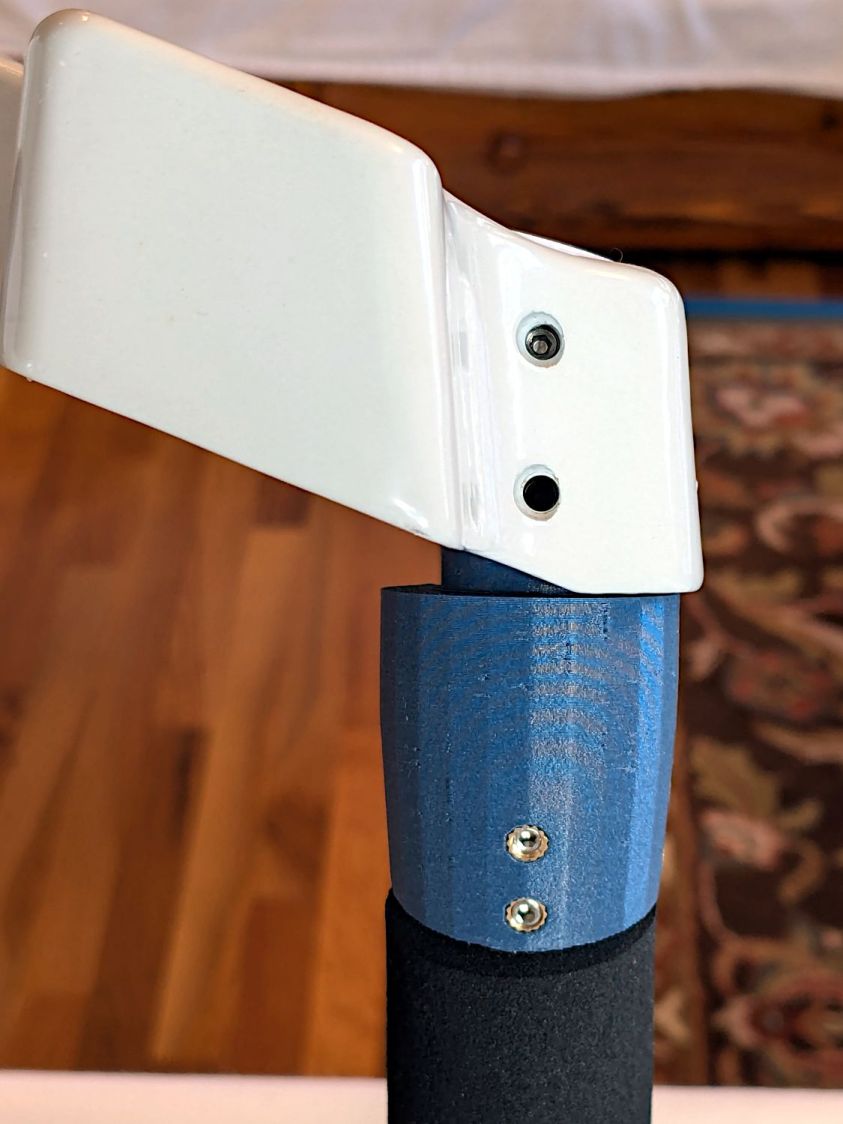
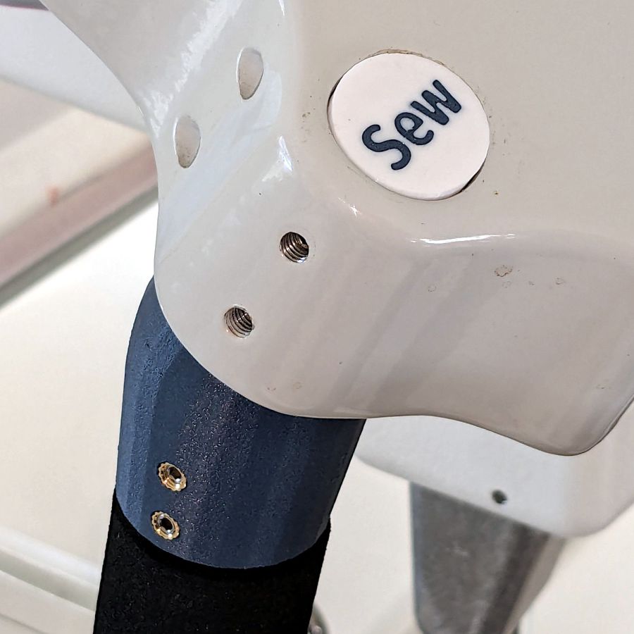
They must print face down to merge the two colors into a single flat surface with a nubbly texture from the steel sheet’s coating.
Disks of adhesive sheet will eventually stick them atop the plugs, but for now they’re just dropped into the holes.
The OpenSCAD source code as a GitHub Gist:
| // Handiquilter HQ Sixteen front handlebar grip angle mount | |
| // Ed Nisley – KE4ZNU | |
| // 2024-11-29 | |
| include <BOSL2/std.scad> | |
| Layout = "Show"; // [Show,Build,Plug,Block,Covers,Cover] | |
| Material = "All"; // [All,Cover,Text] | |
| // Angle w.r.t. base | |
| GripAngle = 20; // [10:30] | |
| // Plug glued, not screwed | |
| PlugGlue = true; | |
| // Square nuts, not inserts | |
| SquareNuts = true; | |
| // Additional length of bottom | |
| AddLength = 0; // [0:20] | |
| // Separation in Show display | |
| Gap = 5; // [0:20] | |
| /* [Hidden] */ | |
| HoleWindage = 0.1; | |
| Protrusion = 0.1; | |
| NumSides = 2*3*4; | |
| ID = 0; | |
| OD = 1; | |
| LENGTH = 2; | |
| Grip = [19.7,22.4,20.0]; // (7/8)*INCH = 22.2 mm + roughness, LENGTH=OEM insertion depth | |
| GripRadius = Grip[OD]/2; // used everywhere | |
| Plug = [15.0,Grip[OD],45.0]; // inserts into handlebar base | |
| PlugRim = [Plug[ID],25.0,10.0]; // … sits against handlebar base | |
| BaseScrewPositions = [[11.0,12.0],[27.0,29.0]]; // setscrew offsets from rim top: side,rear | |
| BaseCutout = [Plug[OD]/2,Plug[ID],10]; // cable cutout into base | |
| BaseCutoutOffset = 18.0; // … centerline position w.r.t. rim | |
| WallThick = 7.0; // should at least fit insert length | |
| SupportSag = 0.4; // vertical sag over support structure | |
| MidLength = AddLength + 3.0; // total length allowing for grip tube stop | |
| TopOD = PlugRim[OD] + 2*WallThick; | |
| BotOD = Grip[OD] + 2*WallThick; | |
| BaseScrew = [4.0,4.8 + HoleWindage,1.0]; // HQ 10-32 screws, LENGTH=capture dent | |
| Insert = [5.4,6.0,6.0]; // M4 inserts in plug rim | |
| //Insert = [4.0,5.0,5.0]; // M4 inserts in plug rim | |
| Screw = [3.5,4.0,1]; // M4 screws through angle block to inserts | |
| ScrewHeadOD = 7.4 + 0.4; // M4 BHCS head + comfort | |
| SquareNut = [4.0,7.0,3.0 + 0.4]; // M4 square nut LENGTH + inset allowance | |
| NutInset = GripRadius – sqrt(pow(GripRadius,2) – pow(SquareNut[OD],2)/4); | |
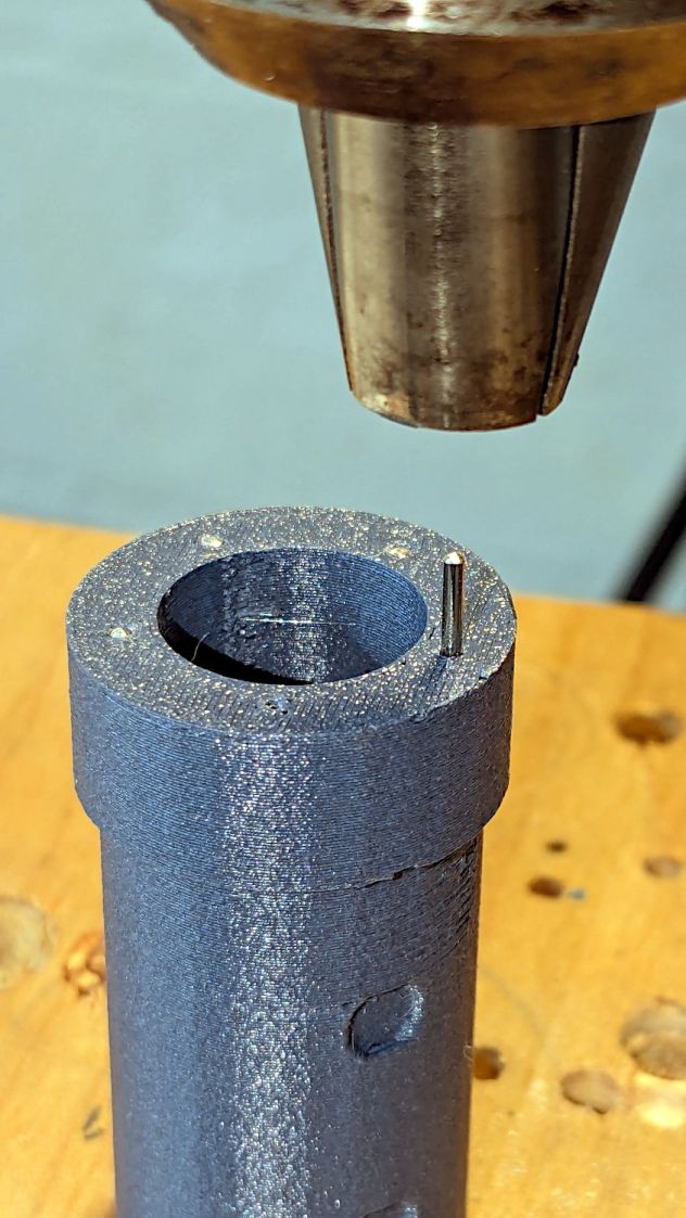
| PinOD = 1.2; // plug reinforcing pins | |
| NumPins = 5; | |
| CoverThick = [3.5,9.5]; // low and high sides of grip covers | |
| CoverAngle = atan((CoverThick[1] – CoverThick[0])/Plug[OD]); | |
| LogoText = ["Sew","Fine"]; | |
| LogoFont = "Fira Sans Condensed:style=SemiBold"; | |
| LogoSize = 7.5; | |
| LogoColor = "Red"; | |
| LogoThick = 0.8; | |
| //———- | |
| // Simulator for aluminum plug replacing handlebar in base | |
| module BasePlug() { | |
| difference() { | |
| union() { | |
| tube(Plug[LENGTH],(Plug[OD] – HoleWindage)/2,Plug[ID]/2,anchor=DOWN); | |
| tube(PlugRim[LENGTH],PlugRim[OD]/2,PlugRim[ID]/2,anchor=DOWN); | |
| } | |
| up(BaseCutoutOffset + PlugRim[LENGTH]) | |
| left(Plug[OD]/4) | |
| resize(BaseCutout) | |
| yrot(90) zrot(180/8) | |
| cylinder(d=1,h=1,$fn=8,center=true); | |
| up(PlugRim[LENGTH]) | |
| right(PlugRim[OD]/2 – 1.0) | |
| cube([2.0,1.0,1.0],center=true); | |
| for (i = [0:NumPins – 1]) | |
| zrot(i*360/NumPins + 180/NumPins) | |
| down(Protrusion) | |
| right((Plug[OD] + Plug[ID])/4) | |
| zrot(180/6) | |
| cylinder(d=PinOD,h=2*PlugRim[LENGTH],$fn=6); | |
| for (k = [0:1]) // recesses in plug to capture base setscrews | |
| for (a = [0:1]) | |
| up(PlugRim[LENGTH] + BaseScrewPositions[k][a]) | |
| zrot(a*90) | |
| right(Plug[OD]/2) | |
| yrot(90) zrot(180/8) | |
| cylinder(d=BaseScrew[OD],h=2*BaseScrew[LENGTH],$fn=8,center=true); | |
| if (!PlugGlue) | |
| for (a = [0:1]) // inserts for angle block screws | |
| up(PlugRim[LENGTH]/2) | |
| zrot(a*90) | |
| yrot(90) zrot(180/8) | |
| cylinder(d=Insert[OD],h=2*PlugRim[OD],$fn=8,center=true); | |
| } | |
| } | |
| //———- | |
| // Block fitting against handlebar base with handlebar angle | |
| module AngleBlock() { | |
| difference() { | |
| hull() { | |
| up((TopOD/2)*sin(GripAngle)) | |
| xrot(GripAngle) | |
| cylinder(d=TopOD,h=PlugRim[LENGTH],$fn=NumSides); | |
| for (a = [1:2:GripAngle+1]) | |
| up((TopOD/2)*sin(a-1)) | |
| hull() { | |
| xrot(a) | |
| cylinder(d=TopOD,h=0.1,$fn=NumSides); | |
| xrot(a-1) | |
| cylinder(d=TopOD,h=0.1,$fn=NumSides); | |
| } | |
| down(Grip[LENGTH] + MidLength) | |
| cylinder(d=(Grip[OD] + 2*WallThick),h=0.1,$fn=NumSides); | |
| } | |
| up((TopOD/2)*sin(GripAngle)) | |
| xrot(GripAngle) | |
| down(SupportSag) | |
| cylinder(d=(PlugRim[OD] + HoleWindage), | |
| h=PlugRim[LENGTH] + SupportSag + Protrusion, | |
| $fn=NumSides); | |
| up((TopOD/2)*sin(GripAngle)) | |
| sphere(d=PlugRim[ID],$fn=NumSides); | |
| cylinder(d=PlugRim[ID],h=(TopOD/2)*sin(GripAngle),$fn=NumSides); | |
| down(MidLength + Protrusion) | |
| cylinder(d=(Grip[ID] – 2.0),h=(MidLength + 2*Protrusion),$fn=NumSides); | |
| down(Grip[LENGTH] + MidLength + Protrusion) | |
| cylinder(d=(Grip[OD] + HoleWindage),h=(Grip[LENGTH] + Protrusion),$fn=NumSides); | |
| up((TopOD/2)*sin(GripAngle)) | |
| xrot(GripAngle) | |
| up(PlugRim[LENGTH]) | |
| right(PlugRim[OD]/2 + 0.9) | |
| cube([2.0,1.0,1.0],center=true); | |
| if (!PlugGlue) { | |
| for (a = [0:1]) | |
| up((TopOD/2)*sin(GripAngle)) | |
| xrot(GripAngle) | |
| up(PlugRim[LENGTH]/2) | |
| zrot(a*90) | |
| yrot(90) zrot(180/8) | |
| cylinder(d=Screw[OD],h=3*PlugRim[OD],$fn=8,center=true); | |
| for (a = [0:3]) | |
| up((TopOD/2)*sin(GripAngle)) | |
| xrot(GripAngle) | |
| up(PlugRim[LENGTH]/2) | |
| zrot(a*90) | |
| right(TopOD/2 – 2.0) | |
| yrot(90) zrot(180/8) | |
| cylinder(d=ScrewHeadOD,h=TopOD,$fn=8,center=false); | |
| } | |
| if (SquareNuts) { | |
| for (a = [0:1]) | |
| for (k = [1,3]) | |
| down(k*Grip[LENGTH]/4 + MidLength) | |
| zrot(a*90) | |
| right(BotOD/2) | |
| yrot(90) zrot(180/8) | |
| cylinder(d=SquareNut[ID],h=BotOD,$fn=8,center=true); | |
| for (a = [0:1]) | |
| for (k = [1,3]) | |
| down(k*Grip[LENGTH]/4 + MidLength) | |
| zrot(a*90) | |
| right(GripRadius + SquareNut[LENGTH]/2 – NutInset/2) | |
| yrot(90) | |
| cube([SquareNut[OD],SquareNut[OD],SquareNut[LENGTH] + NutInset],center=true); | |
| } | |
| else { | |
| for (a = [0:1]) | |
| for (k = [1,3]) | |
| down(k*Grip[LENGTH]/4 + MidLength) | |
| zrot(a*90) | |
| right(BotOD/2) | |
| yrot(90) zrot(180/8) | |
| cylinder(d=Insert[OD],h=BotOD,$fn=8,center=true); | |
| } | |
| } | |
| } | |
| //———- | |
| // Chip fitting against handlebar base matching top angle | |
| // Text will be invisible until sliced | |
| module GripCover(loc=LEFT,matl="Cover") { | |
| if (matl == "Text" || matl == "All") | |
| color(LogoColor) | |
| down(matl == "All" ? 0.01 : 0.0) | |
| text3d(LogoText[loc == LEFT ? 0 : 1],LogoThick,LogoSize,LogoFont, | |
| orient=DOWN,anchor=TOP,atype="ycenter"); | |
| if (matl == "Cover" || matl == "All") | |
| difference() { | |
| intersection() { | |
| yrot(loc == RIGHT ? -CoverAngle : CoverAngle) | |
| cylinder(d=Plug[OD],h=(CoverThick[0] + CoverThick[1]),anchor=CENTER); | |
| cube(2*Plug[OD],anchor=BOTTOM); | |
| } | |
| text3d(LogoText[loc == LEFT ? 0 : 1],LogoThick,LogoSize,LogoFont, | |
| orient=DOWN,anchor=TOP,atype="ycenter"); | |
| } | |
| } | |
| //———- | |
| // Build things | |
| if (Layout == "Cover") { | |
| GripCover(LEFT,Material); | |
| } | |
| if (Layout == "Covers") { | |
| left(Plug[OD]) GripCover(LEFT,"Cover"); | |
| left(Plug[OD]) GripCover(LEFT,"Text"); | |
| right(Plug[OD]) GripCover(RIGHT,"Cover"); | |
| right(Plug[OD]) GripCover(RIGHT,"Text"); | |
| } | |
| if (Layout == "Plug") | |
| BasePlug(); | |
| if (Layout == "Block") | |
| AngleBlock(); | |
| if (Layout == "Show") { | |
| up((TopOD/2)*sin(GripAngle) + Protrusion) | |
| xrot(GripAngle) | |
| up(Plug[LENGTH] + CoverThick[1] + Gap) | |
| yrot(180 + CoverAngle) | |
| GripCover(RIGHT,"All"); | |
| up((TopOD/2)*sin(GripAngle) + Protrusion) | |
| xrot(GripAngle) | |
| up(Gap) | |
| color("Lime",0.75) | |
| BasePlug(); | |
| render() | |
| difference() { | |
| AngleBlock(); | |
| back(50) right(50) | |
| cube(100,center=true); | |
| } | |
| color("Silver",0.5) | |
| down(MidLength + Gap) | |
| tube(3*Grip[LENGTH],GripRadius,Grip[ID]/2,anchor=TOP); | |
| } | |
| if (Layout == "Build") { | |
| mirror_copy([1,0,0]) { | |
| right(BotOD) { | |
| up((TopOD/2)*sin(GripAngle) + PlugRim[LENGTH]*cos(GripAngle) + Protrusion) | |
| xrot(180 – GripAngle) | |
| AngleBlock(); | |
| back(1.5*max(TopOD,BotOD)) | |
| BasePlug(); | |
| } | |
| } | |
| fwd(60) { | |
| left(Plug[OD]) GripCover(LEFT,"Cover"); | |
| right(Plug[OD]) GripCover(RIGHT,"Cover"); | |
| } | |
| fwd(60) { | |
| left(Plug[OD]) GripCover(LEFT,"Text"); | |
| right(Plug[OD]) GripCover(RIGHT,"Text"); | |
| } | |
| } |