
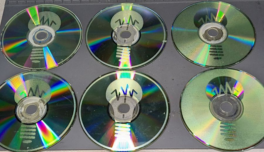
A LightBurn video suggested large scan line intervals for decorative effects, so I adapted the SCP warning labels to fit 4 inch CD/DVD discs, set up the fixture, and Fired The Laser:

The overall effect is, in most lighting, subtle:

The pair on the right with inverted engraving areas are bolder:
From a distance these two look similar, but a line interval of 0.50 mm (on the left) produces a distinct lined effect compared to the overall frosty look for 0.25 mm (open in a new tab & zoom in):
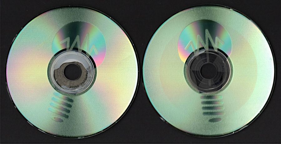
The left and right edges of the disc warp upward as the surface melts and cools, pulling the disc into a potato chip shape. Doing large areas with 0.5 mm spacing produces less warp than 0.25 mm.
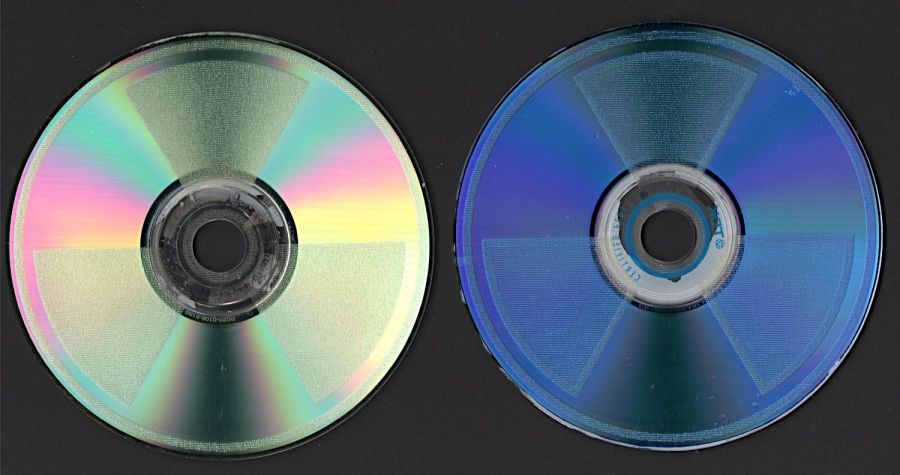
The laser barely fires at 10% power (on the right) and produces a line with a distinct granular look compared the smoother result at 20% (on the left), both at 0.50 mm interval to show the lines:

A 2 mm border at 0.25 mm interval (on the right, with a DVD) appears lighter than the central area at 0.50 mm (the CD on the left does not have the border):
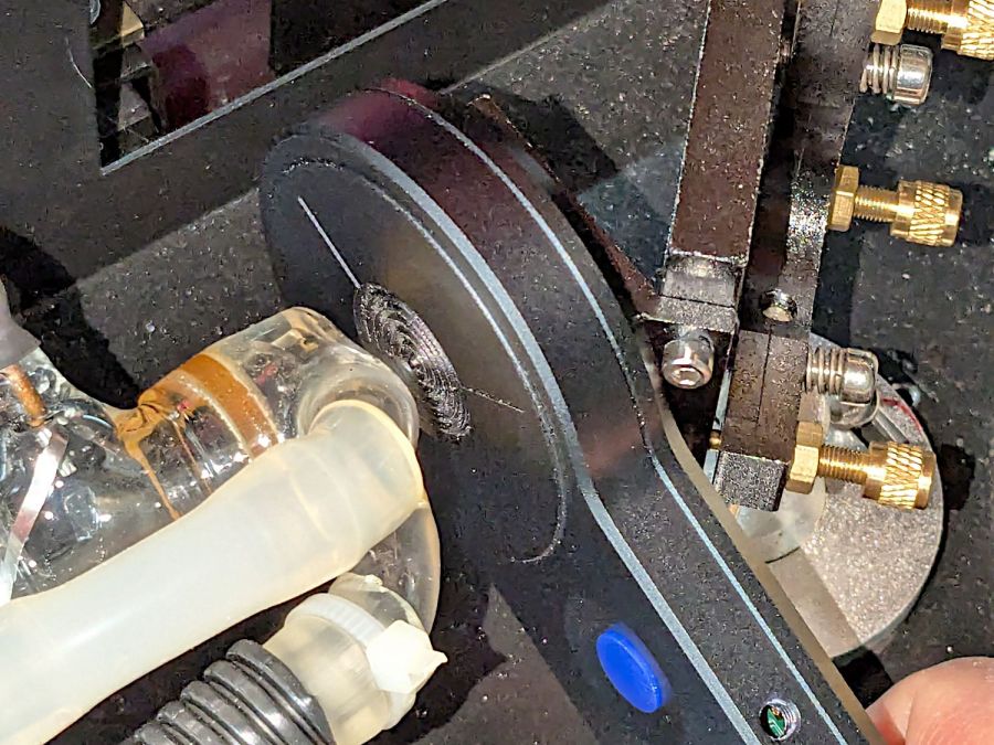
A closer look at the border:

The reason behind the granular effect at 10% power is more obvious with higher magnification:

The spots off to the right are surface imperfections and dirt, not random laser tube firing.
The border and the central area happen on two different passes, so it’s comforting to see how closely the scan lines match.
I glued pairs of discs together with E6000 adhesive to discover whether it’s less awful than cutting and aligning adhesive sheets. Yup, much better, but white adhesive requires better path control to keep it out of the transparent ring around the hub and better quantity control to prevent blobs from squooshing out around the perimeter. Using clear adhesive would help, as would a fresh tube without a plug of cured gunk blocking the nozzle.
Once again, I have Too Many Coasters.


