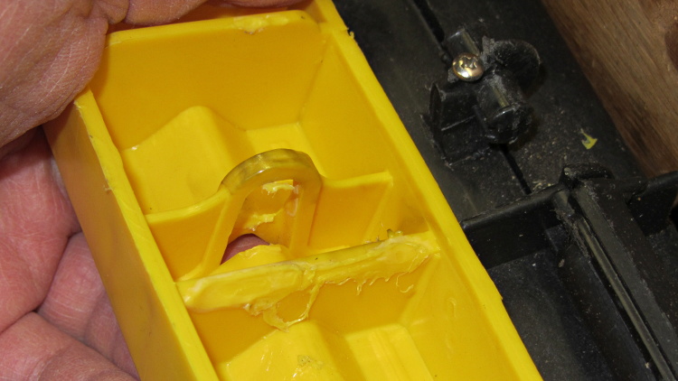
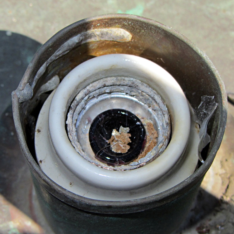
Somehow, we wound up with a broom handle and a broom head, the former missing a threaded stub that was firmly lodged in the latter. A few minutes of Quality Shop Time sawed off the end of the handle and unscrewed the stub to produce this array of fragments:

It’s a cylindrical Thing tailor-made for (or, back in the day, by!) a lathe. My lathe has quick-change gears that can actually cut a 5 TPI thread, but that seems like a lot of work for such a crude fitting. Instead, an hour or so of desk work produced this:

Some after-the-fact search-fu revealed that the thread found on brooms and paint rollers is a 3/4-5 Acme. Machinery’s Handbook has 13 pages of data for various Acme screw threads, making a distinction between General Purpose Acme threads and Stub Acme Threads: GP thread depth = 0.5 × pitch, Stub = 0.3 × pitch. For a 5 TPI thread = 0.2 inch pitch, that’s GP = 0.1 inch vs. Stub = 0.06 inch.
I measured a 5.0 mm pitch (which should be 5.08 mm = 0.2 inch exactly) and a crest-to-root depth of 1.4 mm = 0.055 inch, which makes them look like 3/4-5 Stub Acme threads. But, I didn’t know that at the time; a simple half-cylinder 2.5 mm wide and 1.25 mm tall was a pretty close match to what I saw on the broken plastic part.
Although OpenSCAD’s MCAD library has some screw forms, they’re either machine screws with V threads or ball screws with spheres. The former obviously weren’t appropriate and the latter produced far too many facets, so I conjured up a simpler shape: 32 slightly overlapping cylinders per turn, sunk halfway in the shaft at their midpoint, and tilted at the thread’s helix angle.

The OpenSCAD source code has a commented-out section that removes a similar shape from the shaft between the raised thread, but that brought the rendering to its knees. Fortunately, it turned out to be unnecessary, but it’s there if you want it.
With the shaft diameter set to the “root diameter” of the thread and the other dimensions roughly matching the broken plastic bits, this emerged an hour later:

The skirt thread was 0.25 to 0.30 mm thick, so the first-layer height tweak and packing density adjustments worked fine and all the dimensions came out perfectly. The cylindrical thread form doesn’t have much overhang and the threads came out fine; I think the correct straight-sided form would have more problems.
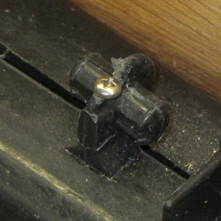
The hole down the middle accommodates a 1/4-20 bolt that applies enough clamping force to keep the shaft in compression, which ought to prevent it from breaking in normal use. I intended to use a hex bolt, but found a carriage bolt that was exactly the right length and had a head exactly the same diameter as the shaft, so I heated it with a propane torch and mushed its square shank into the top of the hexagonal bolt hole (the source code now includes a square recess):

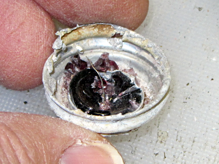
The dimples on the side duplicate the method that secured the original plastic piece: four dents punched into the metal handle lock the plastic in place. It seems to work reasonably well, though, and is certainly less conspicuous than the screws I’d use.
Screwing it in place shows that it’s slightly too long (I trimmed the length in the source code):

It’s back in service, ready for use…
The OpenSCAD source code:
// Broom Handle Screw End Plug
// Ed Nisley KE4ZNU March 2013

// Extrusion parameters must match reality!
//  Print with +1 shells and 3 solid layers

ThreadThick = 0.25;
ThreadWidth = 2.0 * ThreadThick;

HoleWindage = 0.2;

function IntegerMultiple(Size,Unit) = Unit * ceil(Size / Unit);

Protrusion = 0.1;			// make holes end cleanly

//----------------------
// Dimensions

PI = 3.14159265358979;

PostOD = 22.3;              // post inside metal handle
PostLength = 25.0;

FlangeOD = 24.0;            // stop flange
FlangeLength = 3.0;

PitchDia = 15.5;            // thread center diameter
ScrewLength = 20.0;

ThreadFormOD = 2.5;         // diameter of thread form
ThreadPitch = 5.0;

BoltOD = 7.0;               // clears 1/4-20 bolt
BoltSquare = 6.5;          	// across flats
BoltHeadThick = 3.0;

RecessDia = 6.0;			// recesss to secure post in handle

OALength = PostLength + FlangeLength + ScrewLength; // excludes bolt head extension

$fn=8*4;

echo("Pitch dia: ",PitchDia);
echo("Root dia: ",PitchDia - ThreadFormOD);
echo("Crest dia: ",PitchDia + ThreadFormOD);

//----------------------
// Useful routines

module Cyl_Thread(pitch,length,pitchdia,cyl_radius,resolution=32) {

Cyl_Adjust = 1.25;                      // force overlap

    Turns = length/pitch;
    Slices = Turns*resolution;
    RotIncr = 1/resolution;
    PitchRad = pitchdia/2;
    ZIncr = length/Slices;
    helixangle = atan(pitch/(PI*pitchdia));
    cyl_len = Cyl_Adjust*(PI*pitchdia)/resolution;

    union() {
        for (i = [0:Slices-1]) {
            translate([PitchRad*cos(360*i/resolution),PitchRad*sin(360*i/resolution),i*ZIncr])
                rotate([90+helixangle,0,360*i/resolution])
                    cylinder(r=cyl_radius,h=cyl_len,center=true,$fn=12);
        }
    }
}

module PolyCyl(Dia,Height,ForceSides=0) {			// based on nophead's polyholes

  Sides = (ForceSides != 0) ? ForceSides : (ceil(Dia) + 2);

  FixDia = Dia / cos(180/Sides);

  cylinder(r=(FixDia + HoleWindage)/2,
           h=Height,
	   $fn=Sides);
}

module ShowPegGrid(Space = 10.0,Size = 1.0) {

  Range = floor(50 / Space);

	for (x=[-Range:Range])
	  for (y=[-Range:Range])
		translate([x*Space,y*Space,Size/2])
		  %cube(Size,center=true);

}

//-------------------
// Build it...

ShowPegGrid();

difference() {
    union() {
        cylinder(r=PostOD/2,h=PostLength);
        cylinder(r=PitchDia/2,h=OALength);
        translate([0,0,PostLength])
            cylinder(r=FlangeOD/2,h=FlangeLength);
        translate([0,0,(PostLength + FlangeLength)])
            Cyl_Thread(ThreadPitch,(ScrewLength - ThreadFormOD/2),PitchDia,ThreadFormOD/2);
    }

    translate([0,0,-Protrusion])
        PolyCyl(BoltOD,(OALength + 2*Protrusion),6);
    translate([0,0,(OALength - BoltHeadThick)])
        PolyCyl(BoltSquare,(BoltHeadThick + Protrusion),4);

//    translate([0,0,(PostLength + FlangeLength + ThreadFormOD)])
//        Cyl_Thread(ThreadPitch,(ScrewLength - ThreadFormOD/2),PitchDia,ThreadFormOD/2);

	for (i = [0:90:270]) {
		rotate(i)
			translate([PostOD/2,0,PostLength/2])
				sphere(r=RecessDia/2,$fn=8);
	}
}