Experimenting with little squares showed the Y axis has a definite wobble:
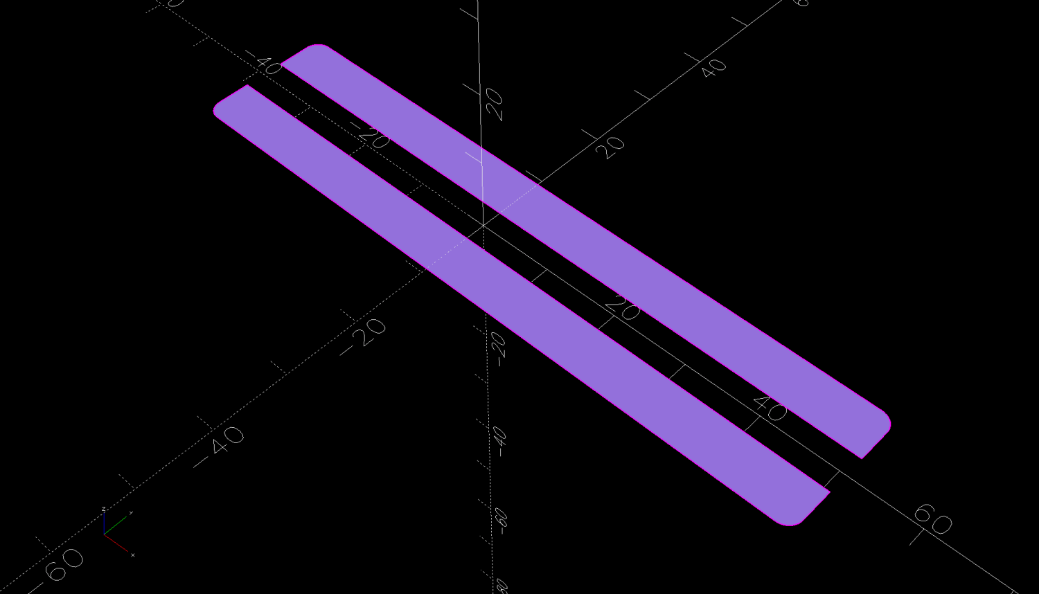
Which suggested a simple test:
I adjusted the laser power to compensate for the speed, with the result being a line burned into white cardboard. The lines are a bit under 0.2 mm wide, roughly the width of the focused spot.
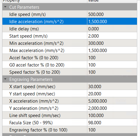
The controller settings for the X and Y axes:

The acceleration values may be affected by the limits in this section:
Assuming the Y axis acceleration is 3000 mm/s², the RepRap calculator shows the Y axis speeds within the 30 mm distance along the vertical sides:

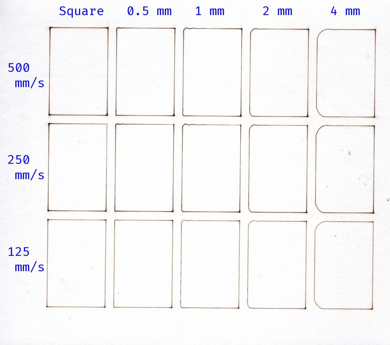
Extracting the useful bits and lining them up for comparison:

The first column in the test results shows perfectly square corners have no problem at any speed, because the controller decelerates to nearly a stop before changing direction.
Rounding the corner to 0.5 mm introduces a distinct wobble in the Y axis that doesn’t change much, probably because the controller still decelerates as it approaches the corner.
The 1 mm radius corners show a distinct overshoot at all speeds. The peak overshoot doesn’t change much between 250 and 500 mm/s, because the RepRap calculator shows the machine barely reaches 250 mm/s by the middle of the side, so 500 mm/s isn’t any faster.
The first overshoot is about 0.2 mm, the first undershoot is a little over 0.1 mm, and the rest are barely visible.
The 2 and 4 mm radius corners have barely visible wobbles. Whether that is due to the head not flexing as much due to the lower acceleration around the larger radius I cannot say.
The machine may not follow the simple RepRap acceleration profile when approaching a corner, let alone a rounded corner.
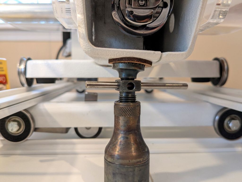
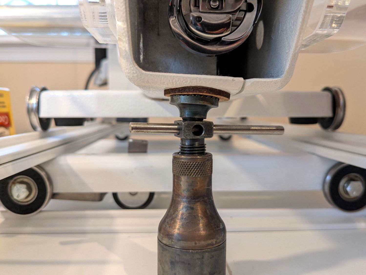
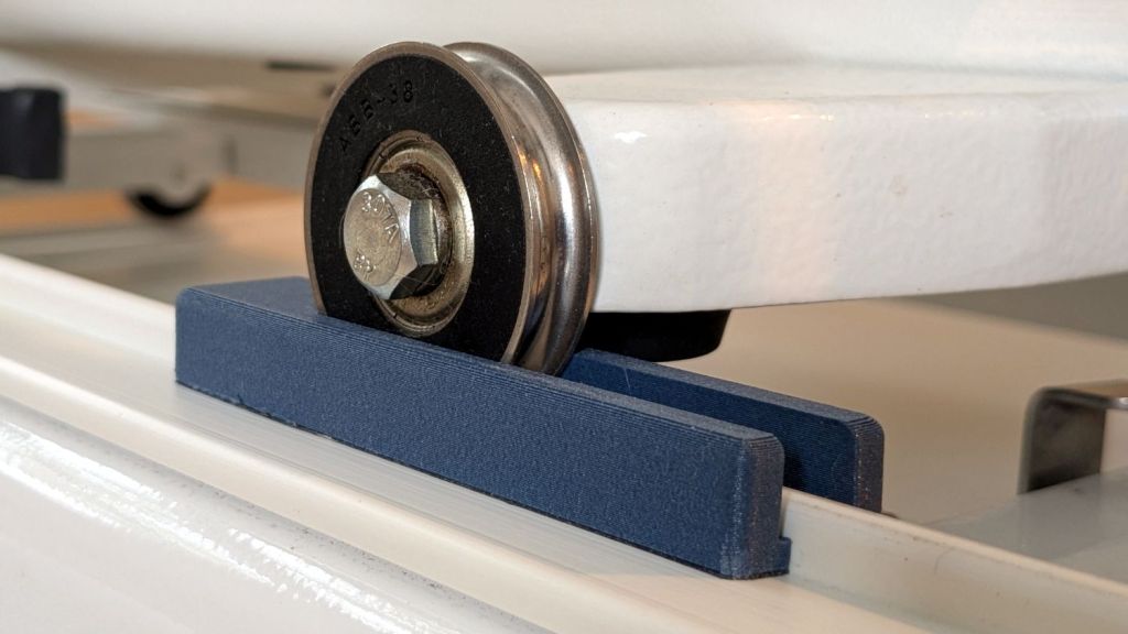
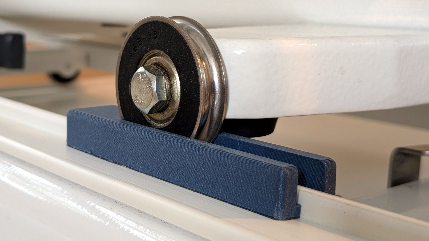
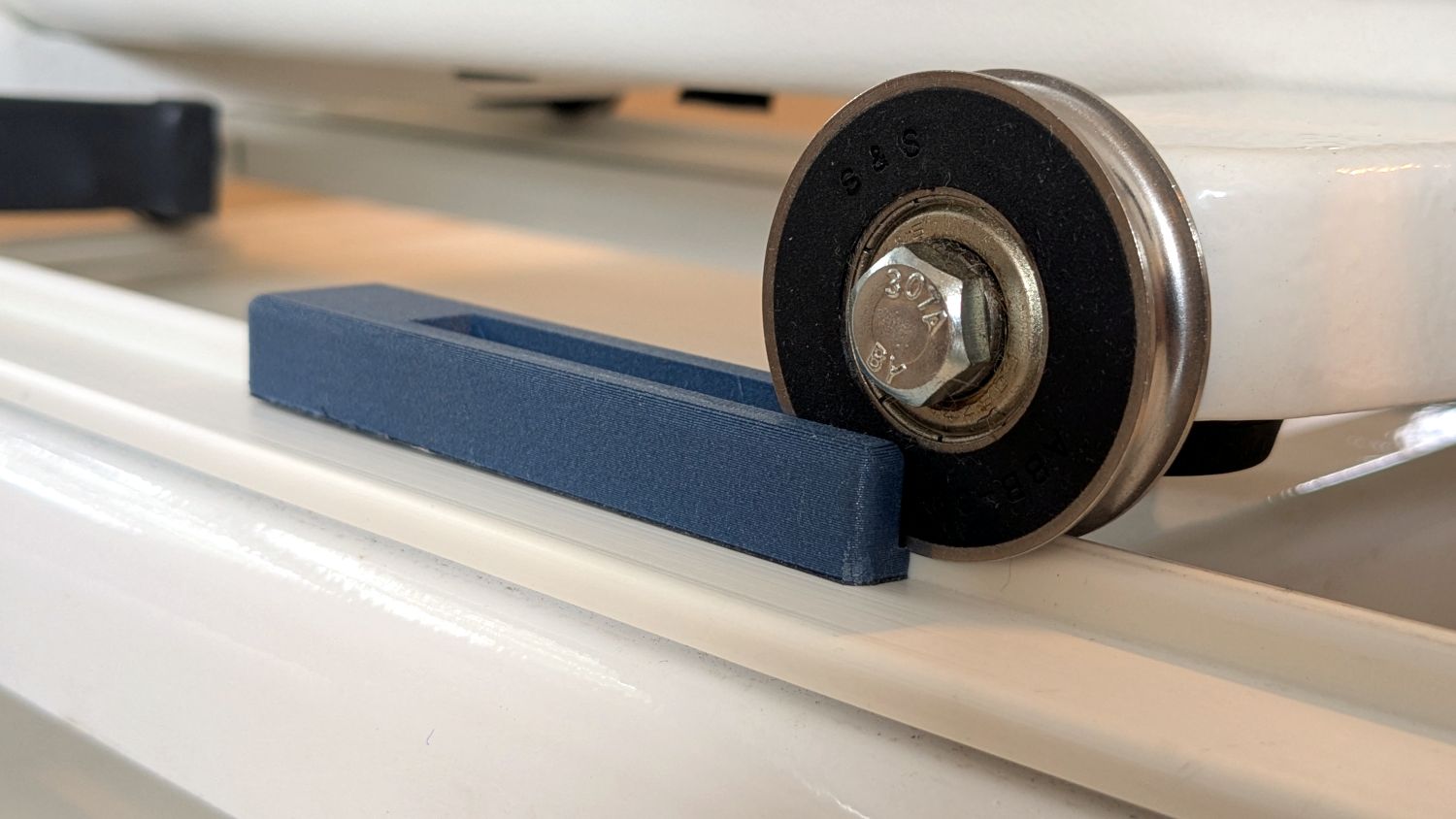
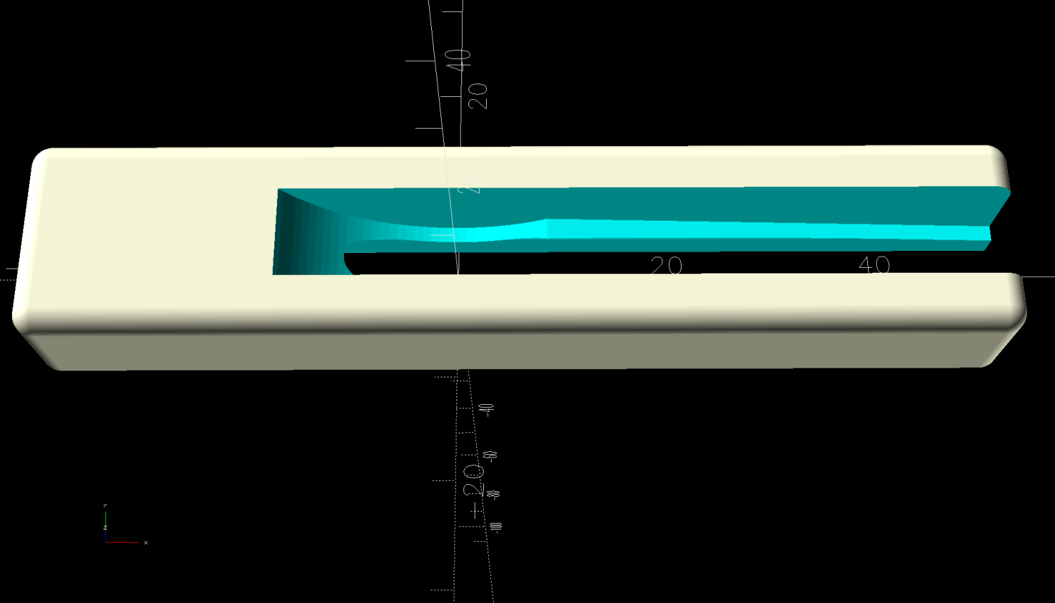
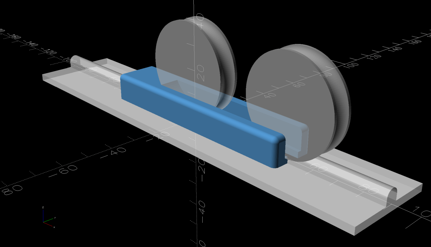
I think attempting to reduce the overshoot by fiddling with the belt tension / hardware fasteners / whatever will be unavailing. The laser head runs on a linear rail along the gantry with plenty of unbalanced mass hanging off the bottom:
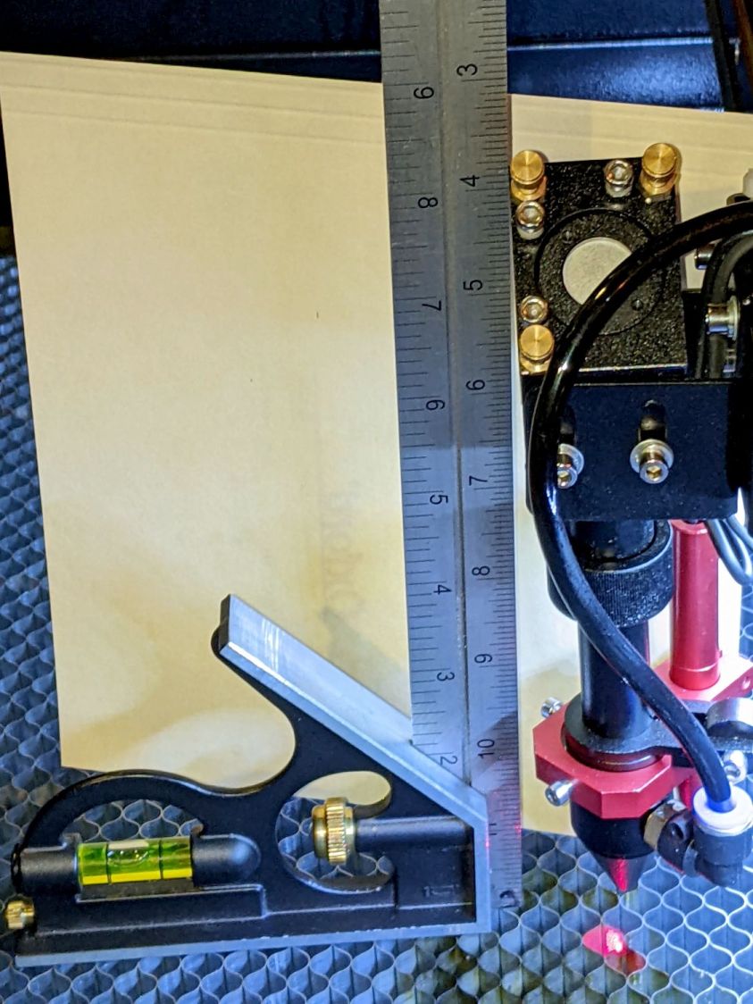
Moving the beam 0.2 mm on the platform by pivoting around the rail 6 inch = 150 mm above amounts to only 0.08°, far less than anything I can measure while adjusting the mechanics.
Slowing down doesn’t help nearly as much as I expected and rounding the corners makes it worse.
Word has it that much spendier machines behave better, which is both comforting and unhelpful.