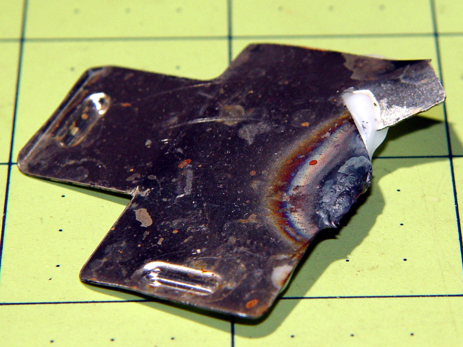
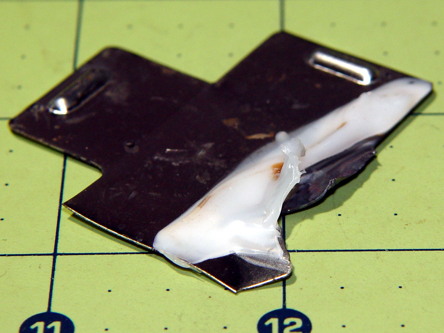
The original cast-iron seasoning recipe, after half a dozen iterations of flax seed oil & high-temperature baking, produced disappointing results:
The key point of seasoning seems to require heating the oil enough to polymerize its molecular thingies, with (IMO) pretty nearly everything else boiling down to woo.
Since that rusting incident, I’ve done this after every use:
- Wipe the pan clean with the same hot soapy water I use for everything else
- Remove crud with the same Scotchbrite / sponge pad I use for everything else
- Rinse and wipe dry with the sponge side of the pad
- Set stove timer for 3 minutes
- Put pan on simmer burner, set to high flame
- Continue cleanup until timer sounds
- Set stove timer for 3 minutes
- Wipe half a dozen drops of flax seed oil around pan with cotton cloth scrap
- Continue cleanup until timer sounds
- Turn off simmer burner
- Wipe pan with that oily cotton scrap
The pan reaches about 300 °F after 3 minutes. The “opening the pores” thing is woo, but a completely dry pan doesn’t spit back and that’s a major plus.
The pan tops out at a bit over 400 °F after a total of 6 minutes. There’s no smoke, no excitement, just a hot pan on the back burner.
Given that I’m washing the pan anyway, the whole “seasoning” operation adds maybe two minutes to the process. By now, it’s entirely automatic.
Nota Bene: Set the timer before turning on the burner and before adding the oil, because you will become distracted and will not remember the pan quietly heating on the back burner. You have been warned.
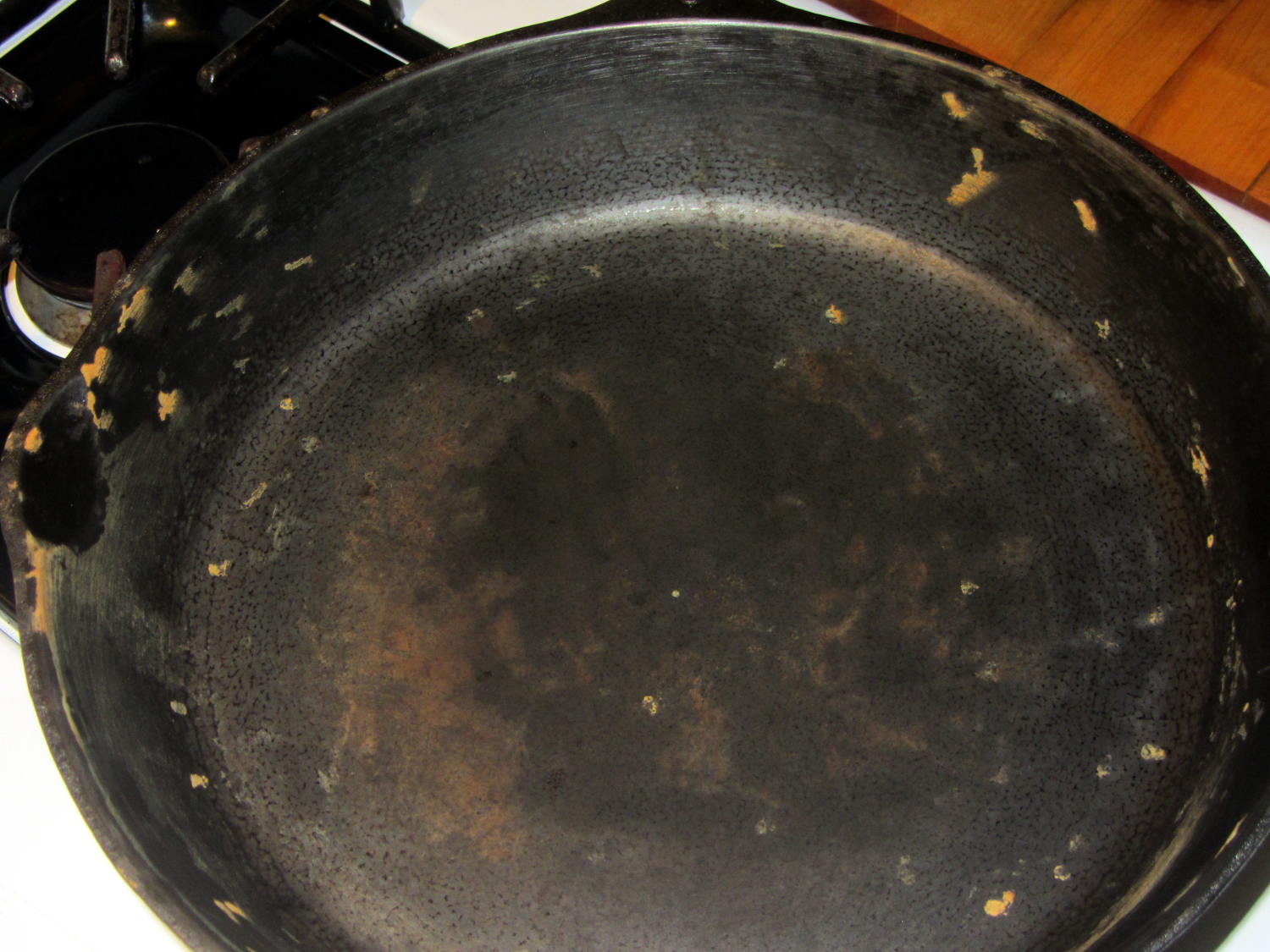
After two months of doing that about once a day:

Granted, it looks about the same as the previous results, but this uniform dull black coating repels water, doesn’t rust, loves oil, wipes clean without scouring, and the daily omelet doesn’t stick hardly at all. Obviously, the key difference is that I’ve polymerized a gazillion coats of oil, rather than half a dozen.
Although I have no idea whether I’m exposing us to lethal free radicals created by the polymerization process, I doubt anybody else knows anything on that subject with regard to their own seasoning technique, so we’re pretty much even. As with most such worries, It Doesn’t Matter.
Next, I’ll just wipe the pan and let it dry in the rack. That coating should eventually wear off, at least in the high-traffic areas; let’s see how little maintenance it requires.