Ed Nisley's Blog: Shop notes, electronics, firmware, machinery, 3D printing, laser cuttery, and curiosities. Contents: 100% human thinking, 0% AI slop.
My original idea for the APRS + voice gadget was a snap-in battery pack replacement holding the circuit boards and connected to an external battery pack. A trio of deadWouxun radios, plus the ready availability of 18650 lithium cells, suggested putting two cells in the backpack, along with the circuitry, and skipping the external pack.
The grid is parallel to the case body and centered left-to-right, with a Y grid line set at the front face of the pack, where it’s also flush with the lid surface. You can read off the coordinates of all the points, feed them into your CAD model, and maybe, with a bit of care, get something 3D-print-able.
Haven’t used it yet, but it’s bound to come in handy at some point.
A long long time ago, I conjured a short bench for our Larval Engineer from a pair of junked folding-table legs and a truly hideous mid-50s Genuine Formica countertop salvaged from the kitchen refurbishment:
Bench Leg – overview
Most recently, it held a pile of test equipment and random stuff next to the MPCNC, whereupon the welds holding the tube with the feet to one of the vertical tubes on the far end failed. It wasn’t in the critical path, so I broke the welds on the other tube, propped the vertical tubes on wood blocks, and continued the mission. Having finally finished those measurements, I could clear off the bench and repair the legs.
I no longer have my welding gear and, in any event, it’s still winter outside, so a low-excitement repair seemed in order: drill suitable holes into the leg crosspiece, make threaded inserts for the tubes, and join them with 3/8-16 bolts.
So, we begin.
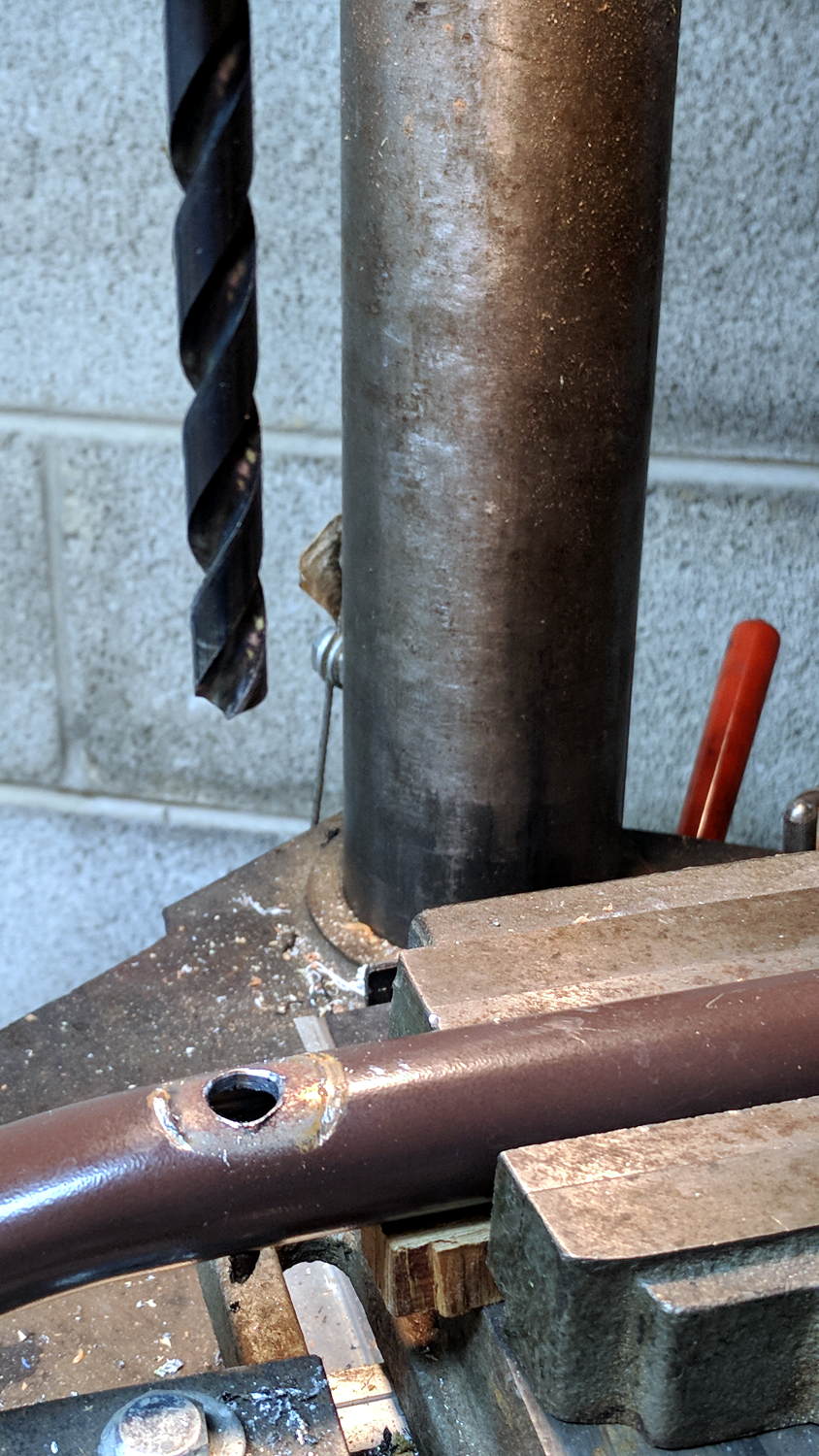
File the broken welds off the foot tube, align it in the drill press vice (where it barely fits!), center drill to make a pilot hole, then poke a 3/8 inch drill completely through to line up both holes:
Bench Leg – through drilling
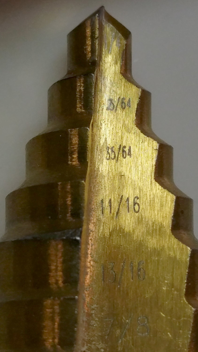
By the Universal Law of the Conservation of Perversity, a 3/8 inch bolt didn’t quite fit the 3/8 inch hole, so I embiggened the holes with a step drill:
Bench Leg – step-drilling to size
The step drill obviously has hard metric diameters labeled as weird inch sizes:
Quasi-inch step drill
I can’t read the second step, either, but it’s apparently 25/64 inch = 9.8 mm, which is just enough over 3/8 inch = 9.5 mm to be useful. The next step is 14 mm = 35/64 inch, so the drill is a bit of a lump.
The leg tubes were a hair over 0.9 inch ID and not particularly round. Tolerances being slack, slice a bit more than two inches off a 1 inch OD aluminum rod:
Bench Leg – sawing rod stock
I wanted more than one diameter in the tubes, but the bolts in my stash topped out at 2 inches and, really, an inch of aluminum won’t go anywhere.
Clean up one end of the rod to 0.9 inch OD, flip, and center drill:
Bench Leg – center drilling insert
Obviously, surface finish and concentricity aren’t critical, but the cleaned-up OD of the left end lined up at barely perceptible mismatch with the (yet to be done) right end.
Sunder in twain:
Bench Leg – sawing leg inserts
Betcha you can’t spot the junction between the two ODs, either.
Drill 3/8 inch through, then discover you (well, I) have neither a drill big enough nor a boring bar small enough to embiggen one end of the hole for a nasty interference fit against the tips of a 3/8 inch hex nut.
Once again, a step drill to the rescue:
Bench Leg – step-drilling insert
Because it’s a step drill, the counterbore isn’t quite deep enough for the whole nut, so turn the nut to fit the recess left by the drill:
Bench Leg – nut shaping
Put a bolt through the insert as a guide, spin the nut on, backstop the insert with a machinist’s parallel jaw clamp (loose, just to give the head somewhere to go), line ’em up, and mash the nut into place with the bench vise:
Bench Leg – nut pressed in place
Clean up the broken welds with a rat tail file, hammer the inserts into the tubes:
Bench Leg – insert installed
Which, as I expected, rounded them nicely while producing an absolutely solid, ain’t gonna work loose, dry joint.
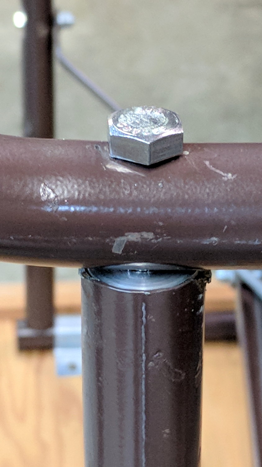
Add threadlocker to the bolts and it’s all good:
Bench Leg – repaired
Stipulated: butt-ugly.
Tell me you’d have fish-mouthed those inserts just for pretty, after noting the factory didn’t bother fishmouthing the vertical tubes before welding them in place.
But it was good for generous dose of Quality Shop Time!
The USB serial adapters I use to capture HP54602 scope and HP8591 spectrum analyzer screenshots, as well as monitor the HP Z8501 GPS time standard, lack unique identifiers and appear as unpredictable device nodes.
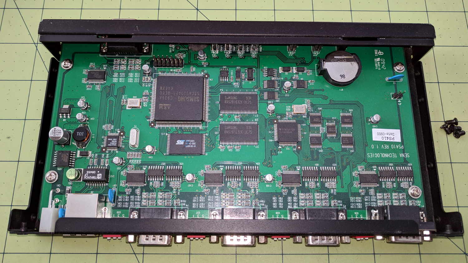
After putting up with this for far too long, I dropped $15 on a Sena Technologies PS410 serial server:
Sena PS410 Serial Server – interior
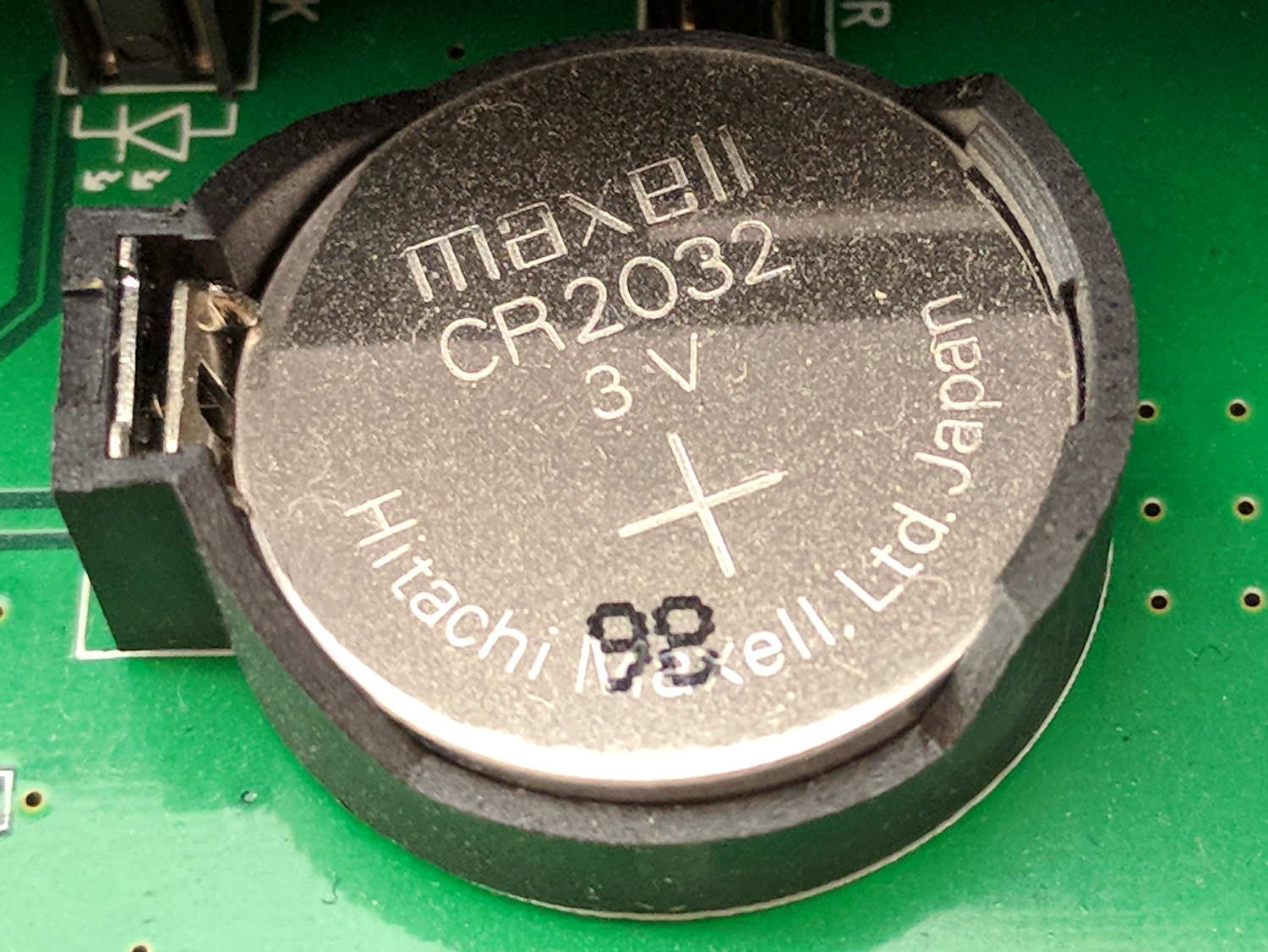
It needed a new lithium coin cell, of course:
Sena PS410 Serial Server – as-received CR2032
The PCB and chip date codes suggest a 2009 build, so “98” might mean August 2009. Whether that’s the manufacturing date or the best used by date, ya never know.
The eBay deal didn’t include the power supply, so I hacked a coaxial jack on the back:
Sena PS410 Serial Server – hacked power jack
A 14 VDC IBM laptop brick from the pile suits the “9 to 36 V” range printed on the case.
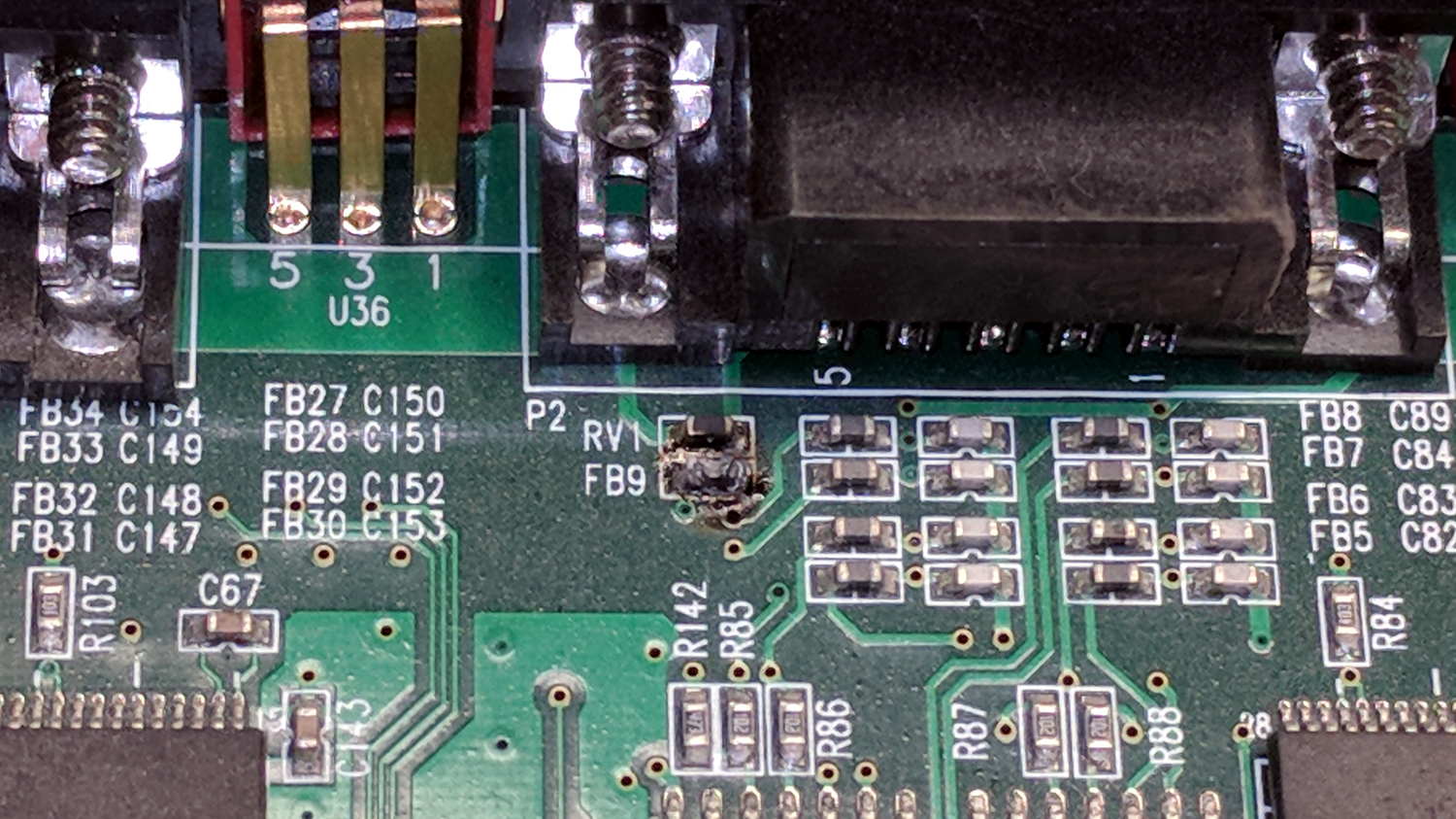
Poking the “factory reset” switch did what you’d expect and the “console” serial port on the front worked fine. I plugged in the scope, the spectrum analyzer, and the GPS receiver, whereupon the bench took on the unmistakable aroma of electronic death:
Sena PS410 Serial Server – charred ferrite chip
Some probing suggests FB9 used to be a ferrite bead between serial port 2’s ground pin and the frame ground.
To compress an afternoon of tinkering into one sentence, there seems to be an occasional 35 VAC difference between the spectrum analyzer and the scope, but only when one or the other is plugged into the PS410. Everything is (now!) plugged into the same branch circuit and, in fact, the same outlet via many power strips, but the difference remains. A different power supply makes no difference, either.
I managed to burn out the ferrite bead on Port 1 with only the scope and the power supply plugged in, by connecting the scope’s ground lead to the shell of Port 2. That makes no sense: there is no voltage difference between the scope’s serial ground and its probe ground.
Something Is Not Right, but I’m baffled.
I have established that the server works fine, even with the charred beads, which is a Good Thing.
Mary acquired this bottle a long time ago and has used it forever, so it has Historic Connotations and cannot be discarded. Alas, the cardboard-and-plastic seal in the cap finally disintegrated; I replaced it with various plastic foams and sheets, none of which worked.
Finally, I found the cork sheet stash while looking for something else and cut out a disk:
Including a waterproof case, some right-angle connectors, and a pipe clamp:
M20 in waterproof case – Tour Easy seat
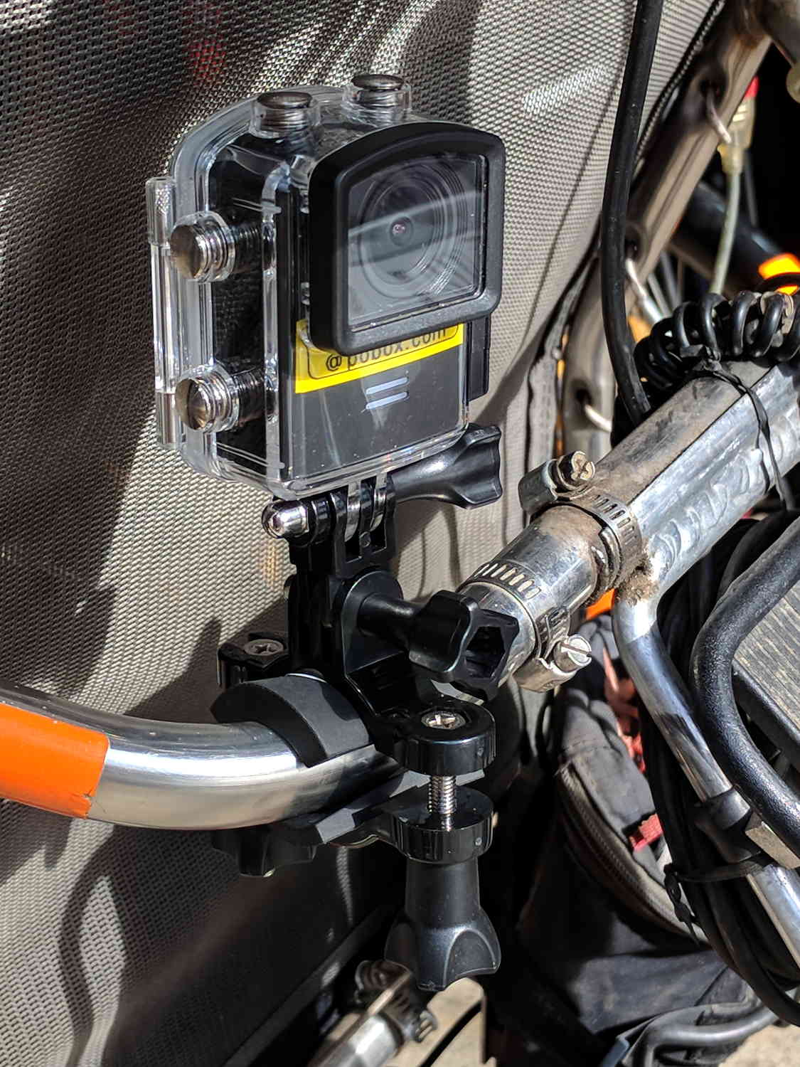
The stack turns out to be about as flexy as one might imagine, definitely a Bad Thing for a bike-mounted camera, and a somewhat more rugged mount seems in order.
A diagram from the M20 manual shows the parts:
SJCAM M20 Overview – Manual pg 5
Some camera dimensions:
40.2 mm wide + 0.5 mm for the Up/Down buttons
21.8 mm thick + 1.0 mm cylindrical front curve + 1.0 mm rear screen
50.0 mm tall + 4.0 mm cylindrical top curve + buttons
21.7 mm OD × 6.0 mm long lens housing, 1.3 mm down from top center
All the edges have neat chamfers or radius rounding on the order of a few millimeters.
Applying the chord equation to the spans inside the rounding:
Front radius: 162.5 mm
Top radius: 42.5 mm
The new batteries survive for a bit over an hour, not quite enough for our usual rides. Rather than conjure a fake battery pack connected to an external 18650 cell with a wire chewed through the case, the least awful way to go may involve a relatively small battery pack (with internal 18650 cells, of course) plugged into the USB port with a right-angle cable and a rigid mount holding both the camera and the pack to the seat frame.
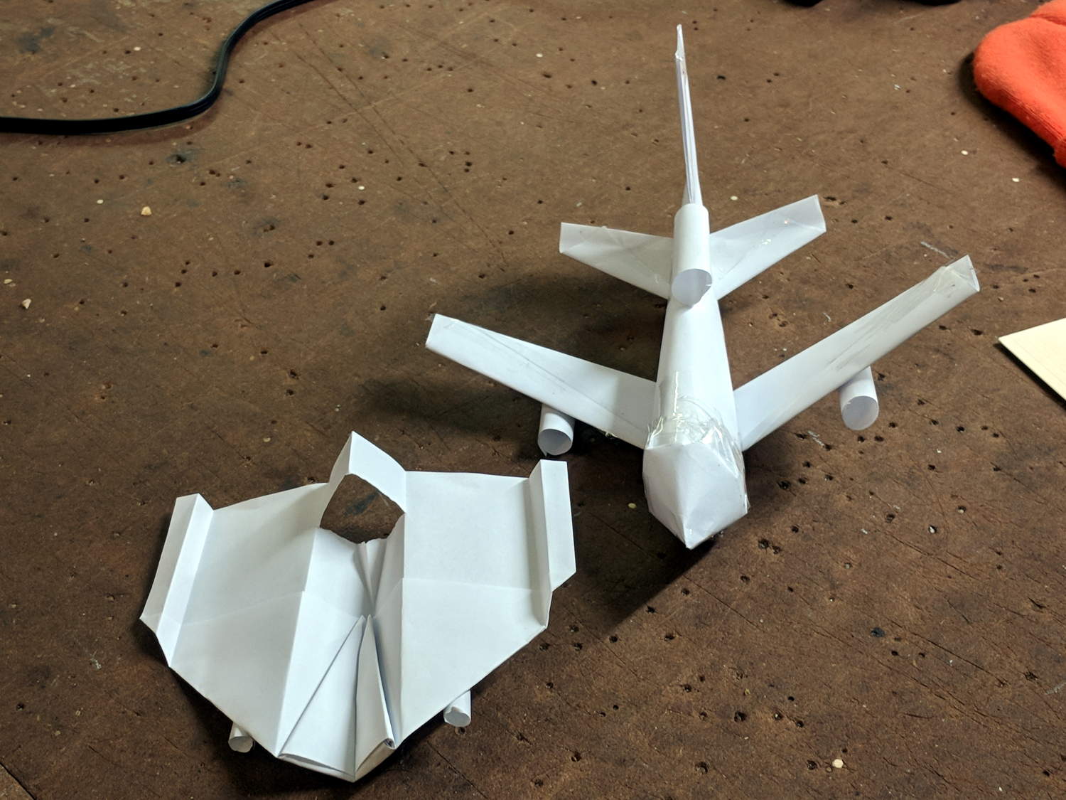
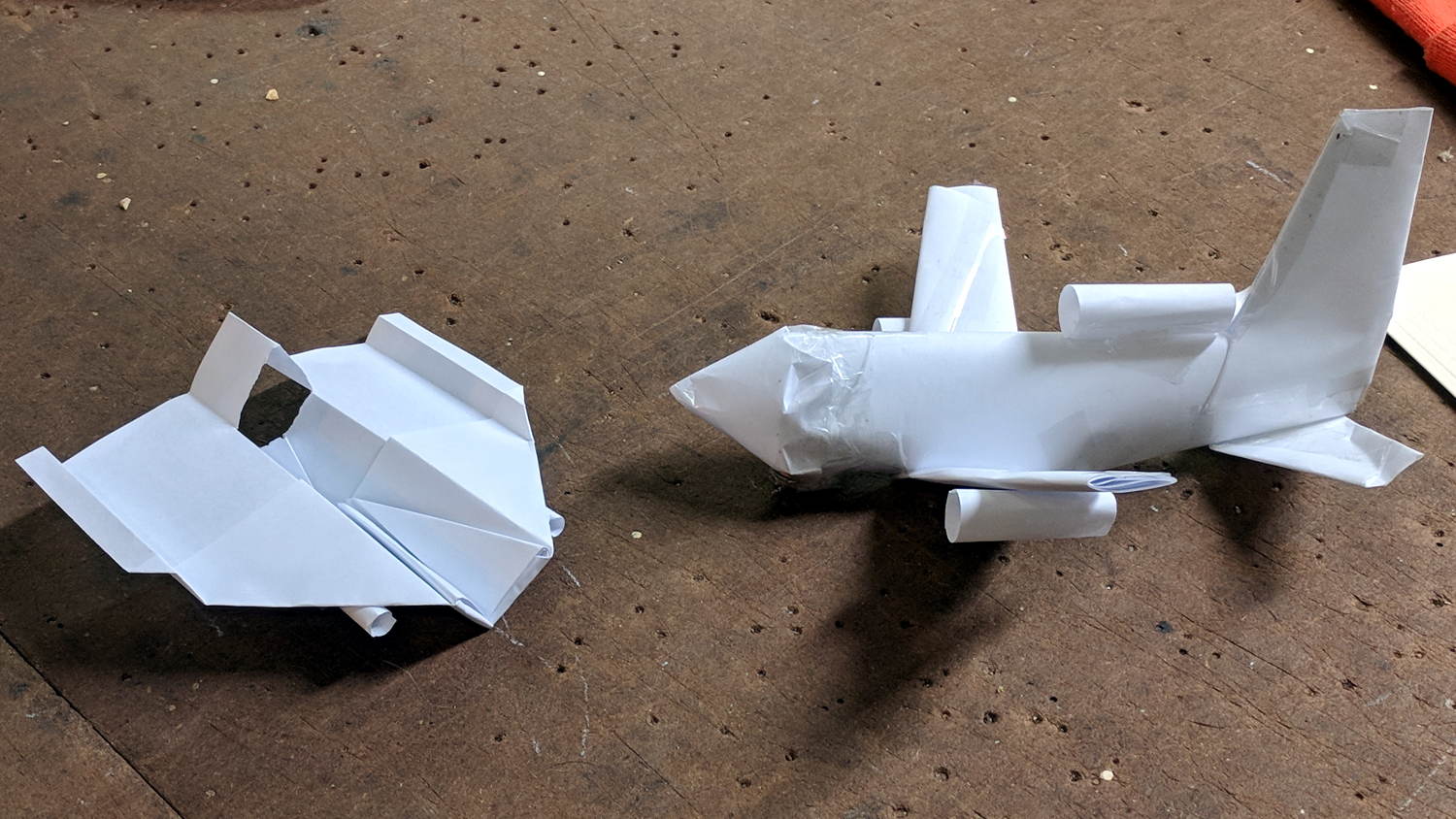
Milo showed how to construct his realistic-looking paper airplane design at Squidwrench, so I had to fold an airplane pattern I learned in fifth grade:
Paper Airplanes – front view
Side views:
Paper Airplanes – side view
Bottom views:
Paper Airplanes – bottom view
His plane flies fine, but “my” airplane has the virtue of simplicity. He had a snippet left over for a fourth engine, so I cut it in half and rolled a pair; the original pattern has none.
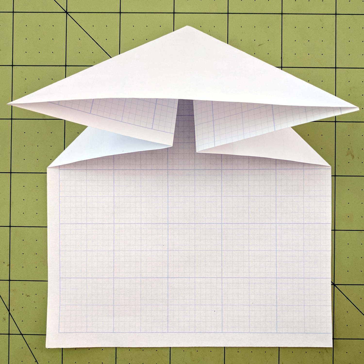
It flies best when made from a sheet of 8-½×11 inch (Letter) paper, but anything will suffice. Here’s how to fold one from a Geek Scratch Pad half-Letter sheet.
Start with two diagonal folds:
Best Paper Airplane Ever – 1
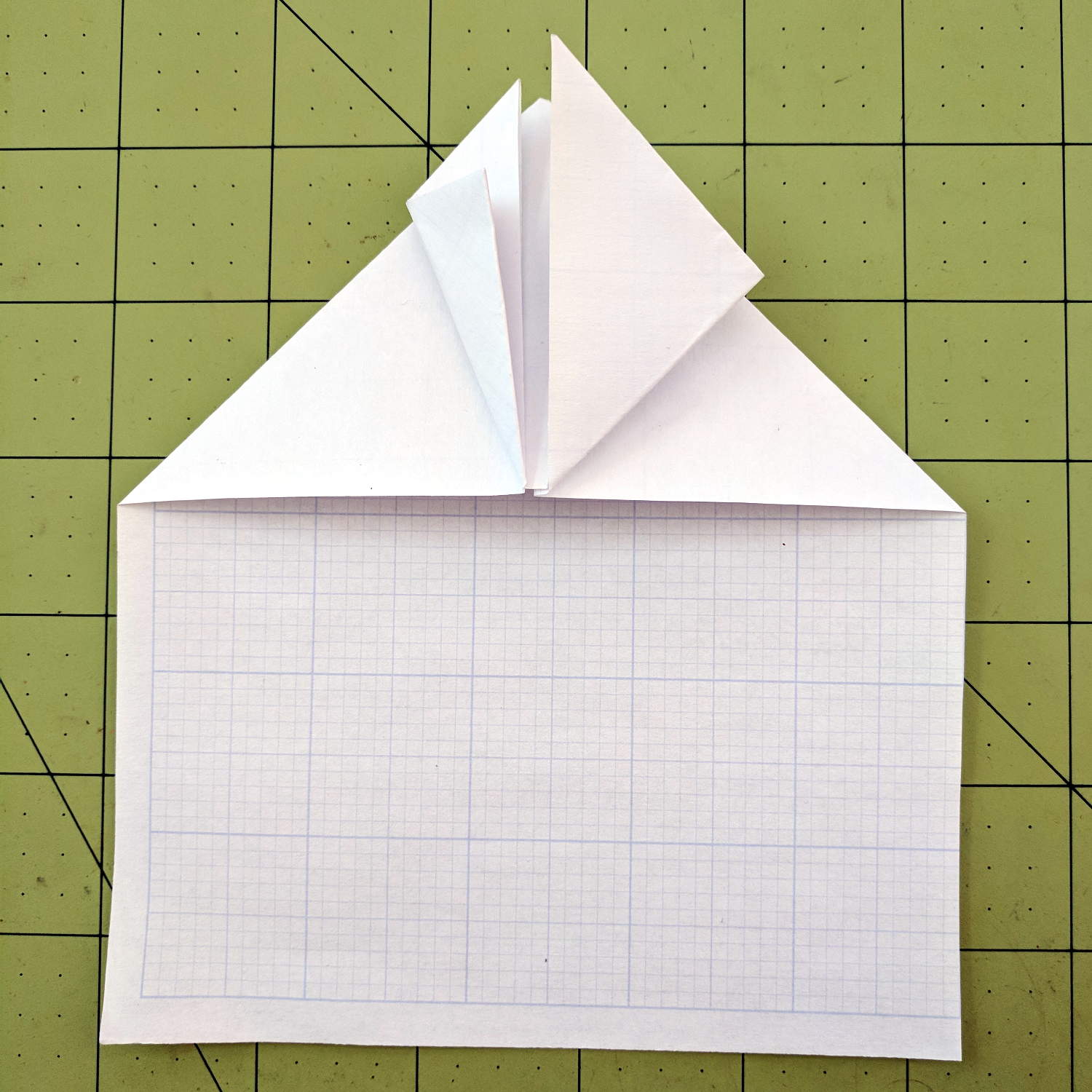
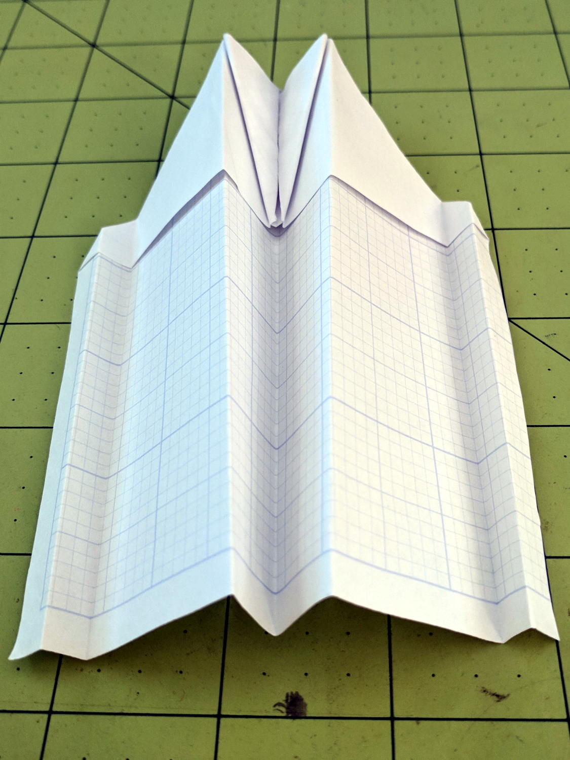
Push the sides in and flatten:
Best Paper Airplane Ever – 2
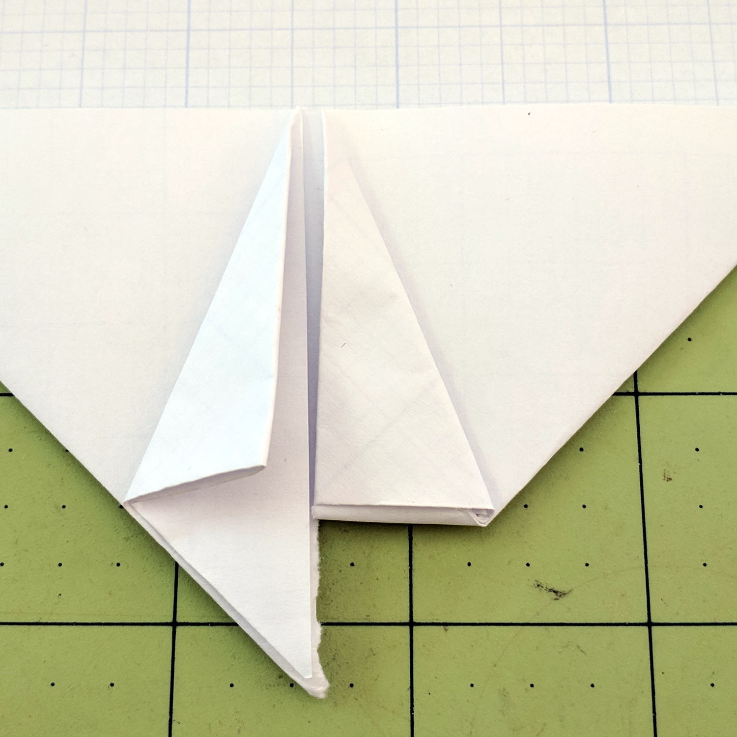
Fold the side tips forward, then again to form pockets:
Best Paper Airplane Ever – 3
I’ve always made those folds to leave a few millimeters of clearance along the centerline, but it probably doesn’t matter.
Tear the fuselage rearward from the nose, along the center line, back to the pockets:
Best Paper Airplane Ever – 4
Tuck the nose pieces into the pockets, flatten firmly, then fold in half lengthwise:
Best Paper Airplane Ever – 5
Fold each wing downward from the pocket, upward to put the edge along the bottom of the fuselage, then fold downward to align the edge at the previous fold:
Best Paper Airplane Ever – 6
Which is harder to describe than to do. The end result should look like this:
Best Paper Airplane Ever – 7
Crisp the folds, tear a square-ish vertical-ish stabilizer, fold a triangle into the fuselage, then un-flatten the airplane into shape:
Best Paper Airplane Ever – 8
Grab just behind the pockets, toss gently upward, and it’ll fly fine the first time. Slightly bend the rear edges of the wing and stabilizer to trim the flight path until it sails gently across the room.
The hole fits a 25 mm fan, but the thing runs cool enough it should survive without forced air; think of it as a contingency. Mounting the case on standoffs seems like a Good Idea, however, as the bottom plate includes many vent slots for Good Circulation.
The top plate builds upside-down, so I had Slic3r add teeny support plugs inside the recessed screw holes. I think button-head screws would fit neatly in the recesses, but we’re obviously not in this for the looks.
The tiny white stud is a Reset switch hot-melt glued into the slot. I plan to just turn off the AC power after shutting the RPi down, so a power-on will suffice as a reset.