Ed Nisley's Blog: Shop notes, electronics, firmware, machinery, 3D printing, laser cuttery, and curiosities. Contents: 100% human thinking, 0% AI slop.
My friend Gee’s bike is a Terry Symmetry, designed for (small) women, which poses challenges when mounting “normal size” components. The Bafang BBS02 speed sensor mount (with a reshaped nut) requires far more clearance between the chainstay and the wheel spokes than the Symmetry has:
Bafang BBS02 Speed Sensor – OEM bracket
The chainstay is nearly parallel to the spokes, so the sensor fits equally poorly anywhere its cable will allow.
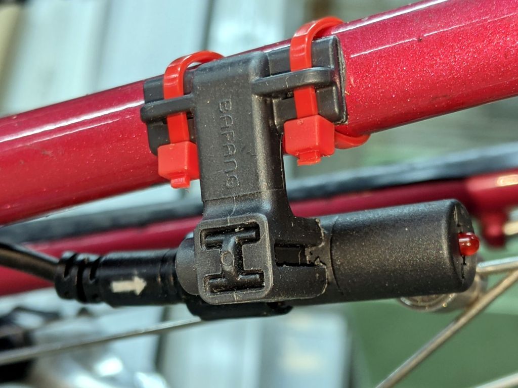
The obvious solution is to reverse the mount and stick it to the outside of the chainstay, but it’s not mmmm symmetric: the other end is closed. Use a pull saw to cut off the closed end, stick the sensor post in the other way, and then it fits fine:
Bafang BBS02 Speed Sensor – reversed bracket – top
That’s the front view, so it’s on the right side in front of the handlebar. I think it’s usable with either a thumb or fingertips from a hand on the top of the bar. The handlebar lacks tape, as mounting the brake sensors poses a challenge.
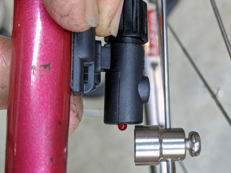
The view from the rear isn’t too revealing:
Bafang Throttle adapter – rear view
Not too unsightly, but definitely not a standard setup!
All of the Bafang BBS02 displays have a compression clamp intended for more-or-less standard 22.2 mm handlebars, as found on typical upright BMX-ish bikes suitable for conversion to e-bikes and, oddly, our Tour Easy recumbents. My friend’s bike has drop-bar handlebars with a 25.4 mm (yes, exactly 1 inch) center section that just isn’t going to fit through that hole.
The least awful solution involved summoning an adapter from the vasty digital deep:
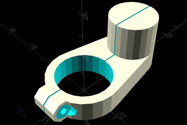
Display adapter mount – solid model
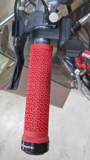
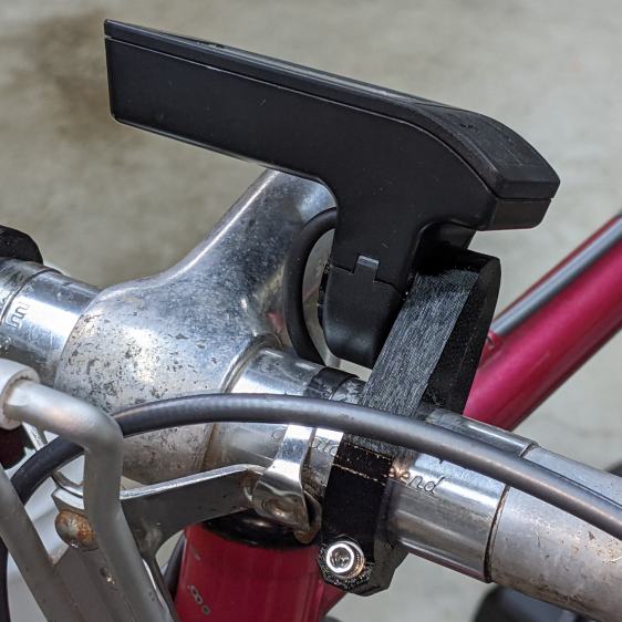
The hole clamps around the handlebar with an M3 SHCS pulling it snug and the display clamps around the peg to hold everything together:
Bafang Display adapter – front view
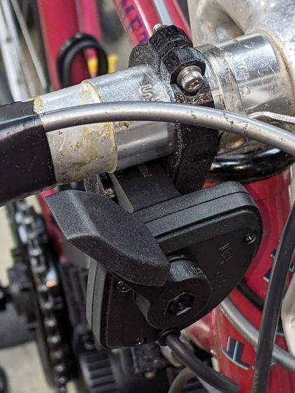
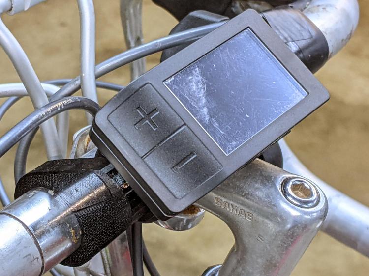
There’s not much to see from the side:
Bafang Display adapter – left view
Those scuffs arrived on the protective plastic film!
The OpenSCAD source code includes some cruft from an idea that didn’t work out quite right:
My friend rides about the same way we do, except from a much higher perch, so I’ll start her off with a configuration similar to the one we settled on for Mary’s Tour Easy.
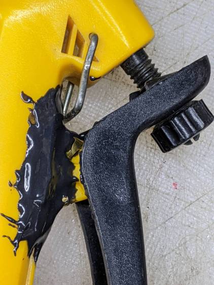
A winning entry in the “The Bigger the Blob, the Better the Job” category:
Garden Sprayer – pivot repair
Buried under the epoxy is the flimsy tab with the pivot around which the handle moves. Any sideways force will did snap the tab off flush with the body. I had previously repaired it with solvent adhesive, so something more substantial seemed appropriate.
A closer look shows the edges of the brass flange I formed around the tab to absorb the stress:
Garden Sprayer – pivot repair – detail
It’s pretty much fully depreciated, but if I don’t use the epoxy it will go bad on the shelf, so …
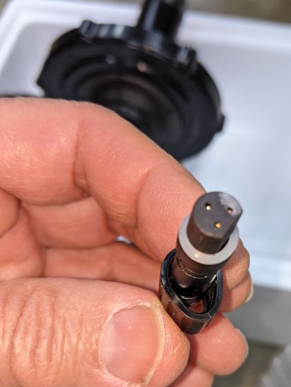
A Bafang BBS02 (for a friend’s upright bike) arrived with a deformed speed sensor nut:
Bafang BBS02 – Deformed speed sensor nut – end view
It traveled halfway around the planet while trapped underneath the motor and, if it rode in the top layer or two of containers, the combination of pressure and heat would be irresistible.
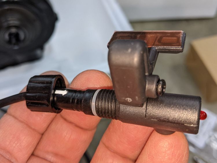
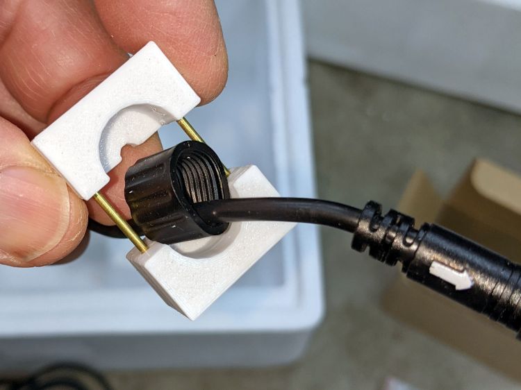
The plastic was stiff and I couldn’t force the nut over the connector using as much force as seemed reasonable:
Bafang BBS02 – Deformed speed sensor nut – test assembly
On the upside, the nut just compresses the silicone washer between the connector and the sensor to make a waterproof joint, so it need not have perfect threads or a uniform shape. Once the nut is in place, it will likely never be removed and should never bother anyone else.
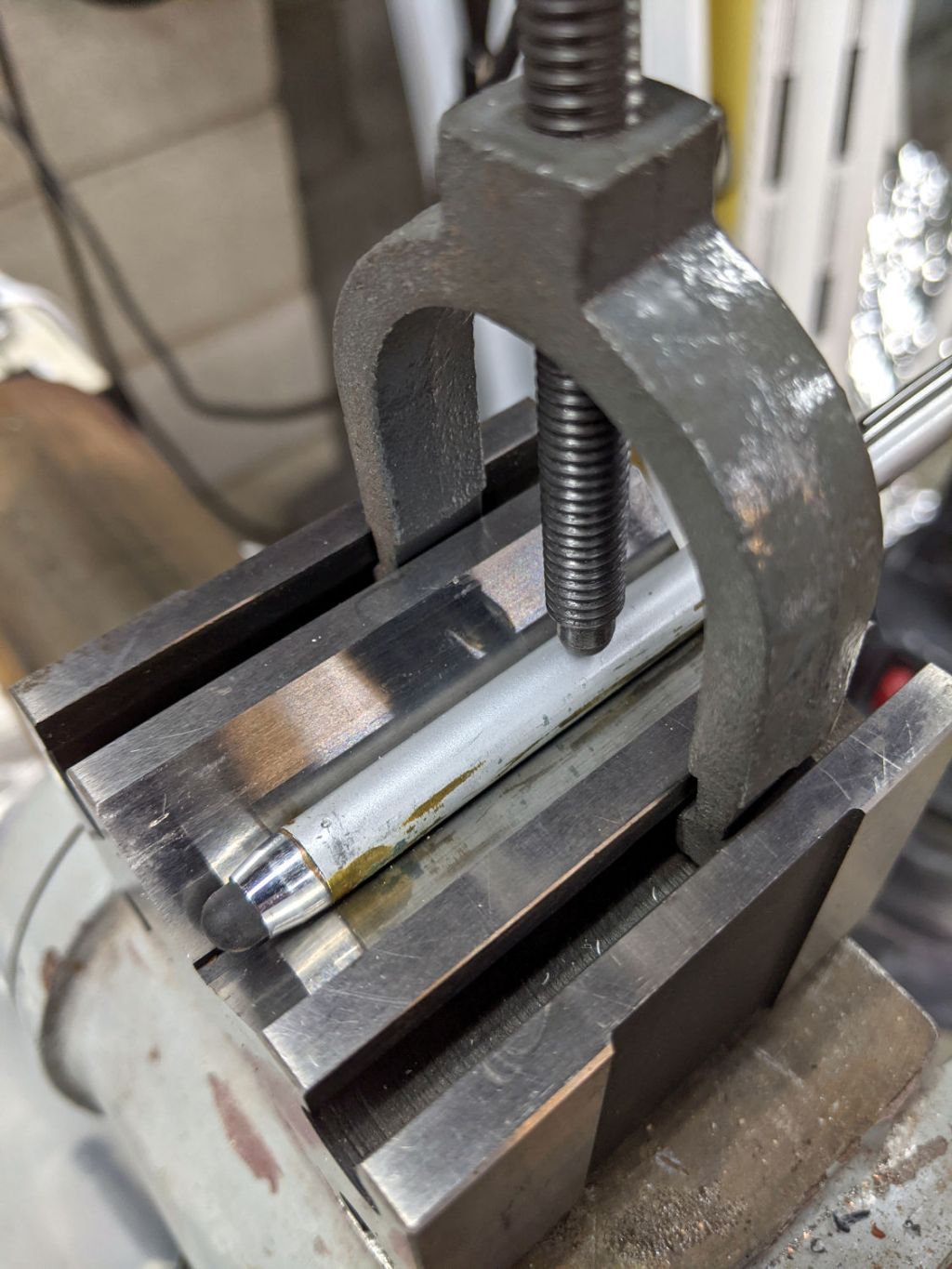
Being unwilling to apply a hot-air gun near the cable, I decided to try slowly cold-forming the nut inside a mold:
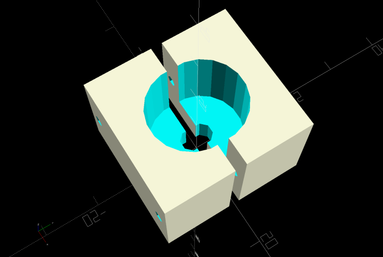
Sensor Nut mold – solid model
The gap isn’t a kerf: the two halves meet to form a cylindrical pocket. The smaller holes fit a pair of brass tubes keeping the halves lined up while I arrange things:
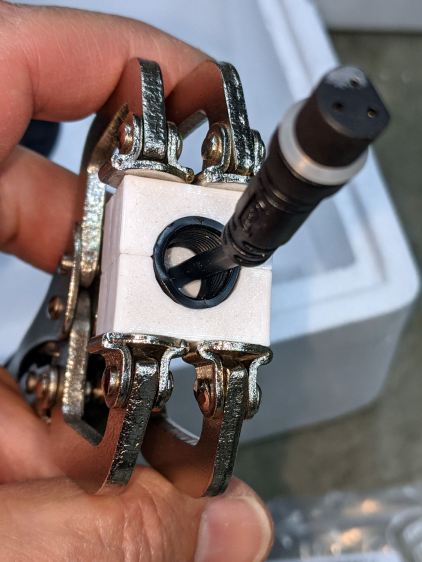
A few days of squashing made it round-er, whereupon I applied the clamp directly against the remaining high point with the other side cradled in the mold. It still doesn’t slide over the connector body, but I’m not in a rush.
Bafang tech support generously sent a speed sensor extension cable from which I can extract a good nut, which will require cutting and splicing the cable from the motor.