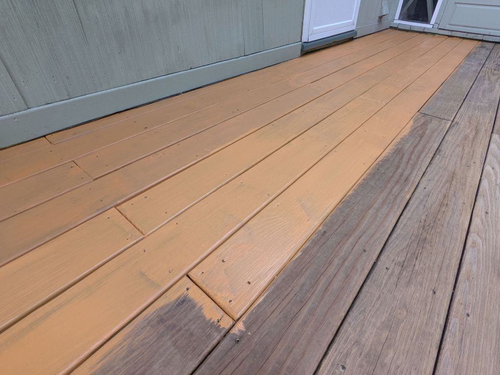
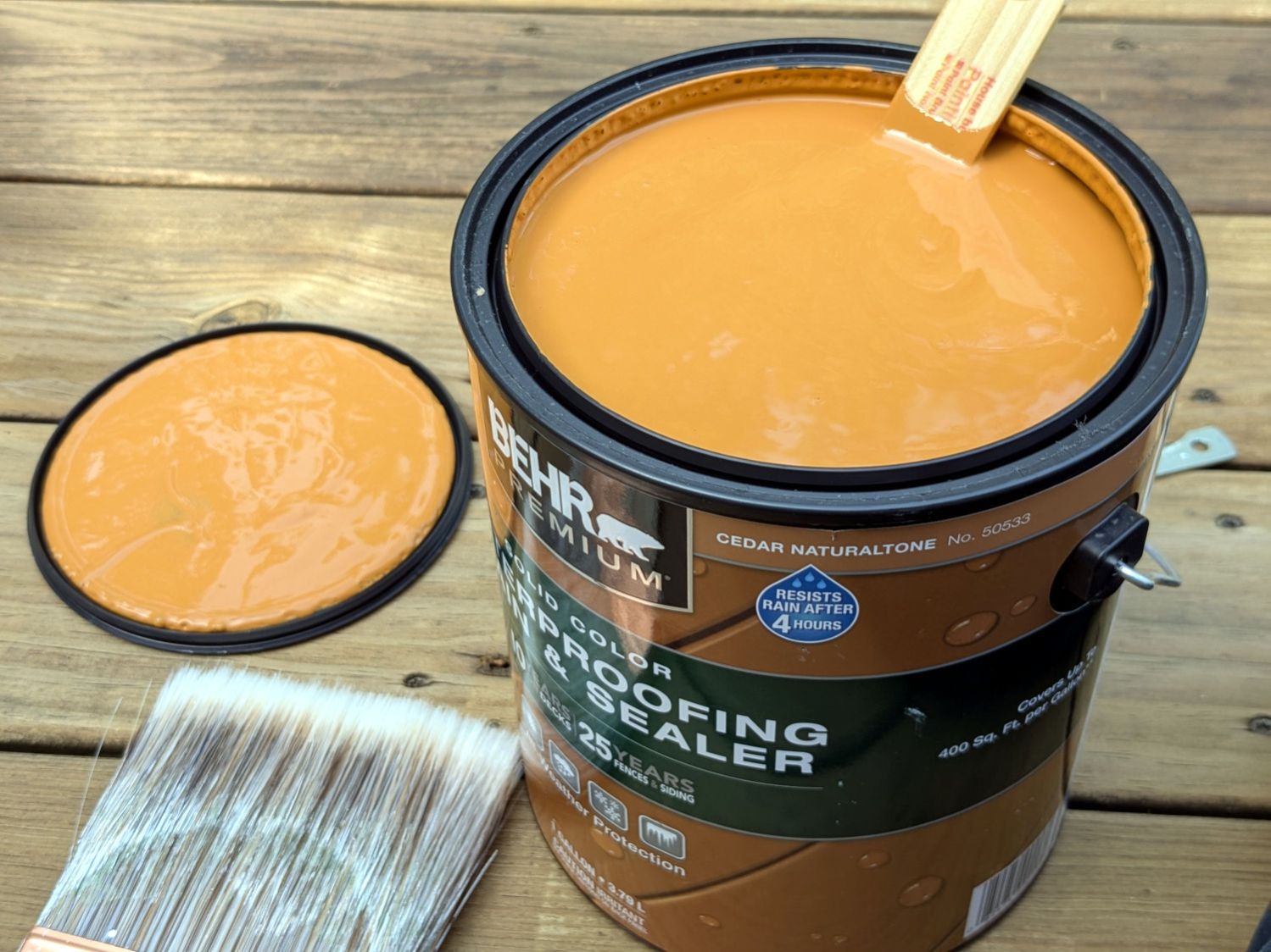
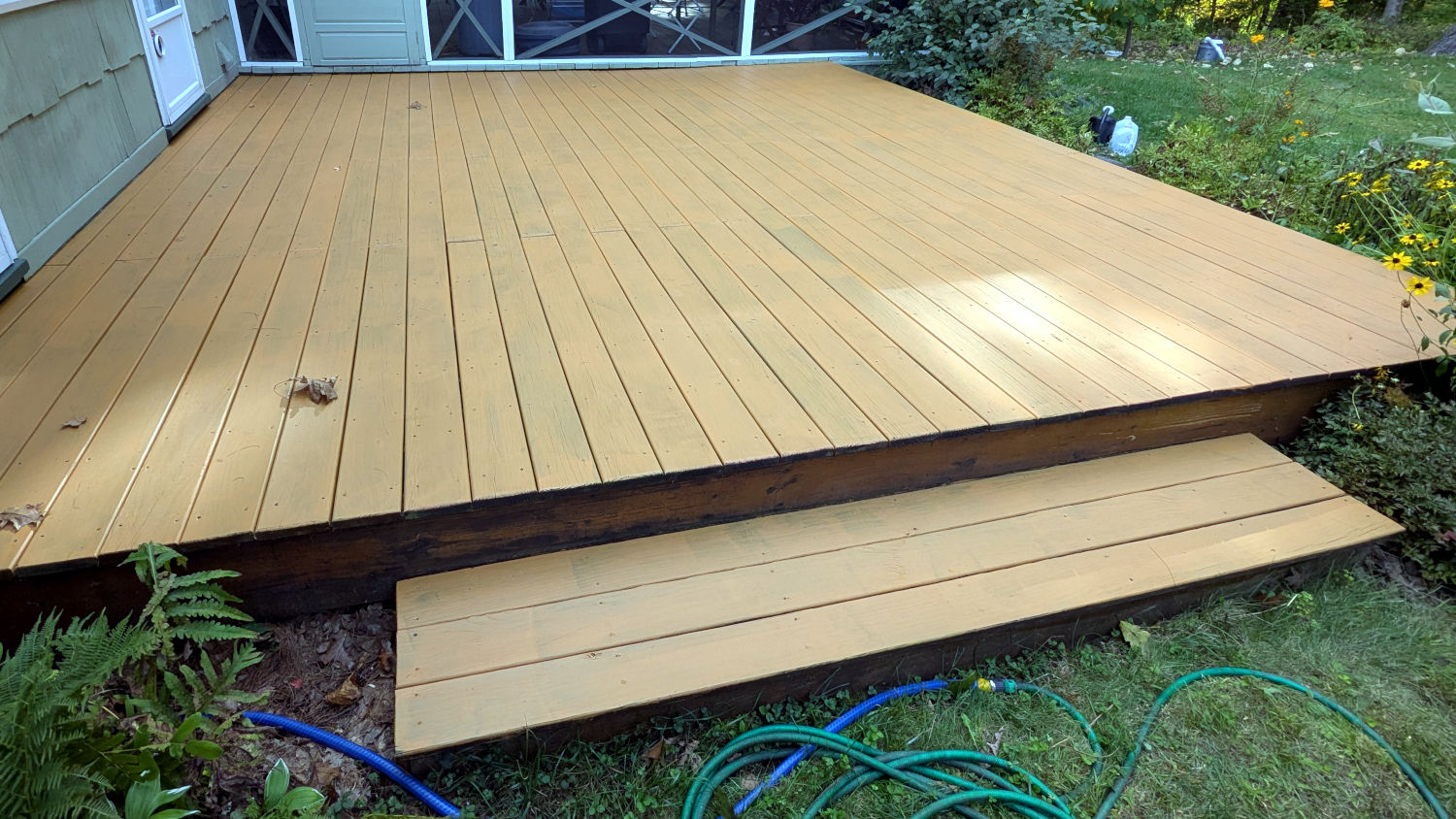
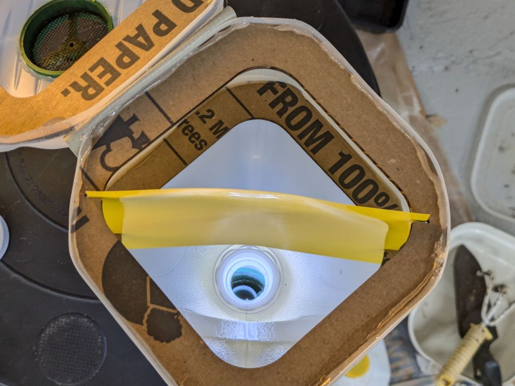
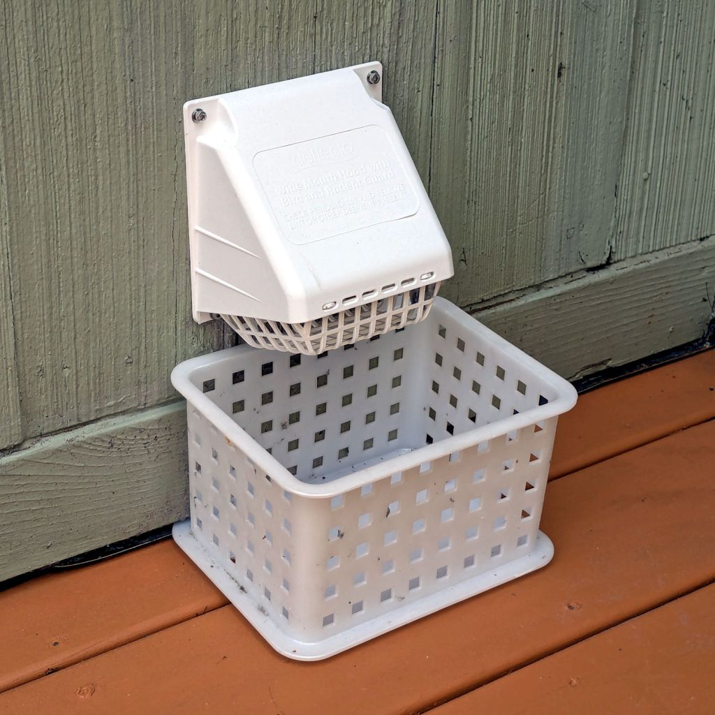
The Smell of Molten Projects in the Morning

Ed Nisley's Blog: Shop notes, electronics, firmware, machinery, 3D printing, laser cuttery, and curiosities. Contents: 100% human thinking, 0% AI slop.

Category: Home Ec

Things around the home & hearth

  • Shower Head Hose Clamp

    Shower Head Hose Clamp

    The new shower head’s hose dangled directly in front of the faucet knob, so I conjured a simple clamp to pull the down-going half over to the side of the stall and keep the up-going half away from the faucet:

    Shower head hose clamp - installed
    Shower head hose clamp – installed

    The black nylon M6 screw goes into a hole tapped in the plastic cap atop the aluminum extrusion; I was mildly surprised that worked as well as I hoped. It’s basically invisible from outside the shower stall.

    Stipulated: laser-cut 3 mm acrylic probably isn’t the right material for the job, but it’s a quick & easy way to discover if that’s the right place to clamp the hose.

    While installing those two pieces, it occurred to me the result would be much stronger if the two “jaws” overlapped and had a pair of screws holding them together, so the LightBurn layout includes that idea for the next time:

    Shower Head Hose Clamp - LightBurn layout
    Shower Head Hose Clamp – LightBurn layout

    The Hole Template simplified getting the hole dead center in the plastic cap, because drilling it required an awkward reach across the end of the vanity.

    There is zero chance this will fit your shower & hose, but now you have the general idea.

  • HQ Sixteen: Nose Ring Lights

    HQ Sixteen: Nose Ring Lights

    We don’t know what the proper term might be for this part of the machine, but it looks sorta like a nose and the lights form most of a ring around it, so I’m going with “Nose Ring Lights”:

    HQ Sixteen Nose Ring lights - front view
    HQ Sixteen Nose Ring lights – front view

    The general idea is to put more light on the quilt than the Chin Light, which looked pretty good until the COB LED strip started flickering as the LEDs failed.

    Handi-Quilter sells a ring light for machines manufactured a decade later than ours, but it uses a built-in USB jack this machine lacks.

    One of two (apparently) unused M4 holes on the left side of the machine frame suggested a mounting point for a 3D printed bracket:

    HQ Sixteen Nose Ring Lights - solid model
    HQ Sixteen Nose Ring Lights – solid model

    The ramp matches the 3° (-ish) mold draft of the machine frame, which I initially ignored by angling the tab, but a tilted frame looked awful; it’s now aligned with local horizontal..

    A few iterations got all the pieces & holes in their proper places:

    HQ Sixteen Nose Ring lights - iterations
    HQ Sixteen Nose Ring lights – iterations

    The smaller (rampless) bracket has three LED strips, but a quick test showed more light would be better:

    HQ Sixteen Nose Ring lights - bottom view
    HQ Sixteen Nose Ring lights – bottom view

    The lack of a transparent-ish cover is obviously unsuitable for a commercial product, but the key design goal is to not interfere with spreading as much light as possible across as much of the quilt as possible. The black JB Weld Plastic Bonder blobs keep the 24 VDC supply out of harm’s way, which is as good as it needs to be for now.

    The bracket has three sides, because the right side of the machine has all the thread guide hardware. Putting anything over there seemed likely to interfere with either thread movement or fingers making adjustments.

    Fortunately, the wider bracket doesn’t stick out too far beyond the machine frame and the doubled LED strips create a much smoother light pool:

    HQ Sixteen Nose Ring lights - left front view
    HQ Sixteen Nose Ring lights – left front view

    Yes, the quilt is focused and the LED frame is blurred.

    The larger light-emitting area reduces the shadow under the left rod (supporting the ruler foot) enough to be unobjectionable.

    A 0.2 mm layer thickness transforms the smooth ramp into stair steps:

    HQ Sixteen Nose Ring Lights - PrusaSlicer
    HQ Sixteen Nose Ring Lights – PrusaSlicer

    They’re inconspicuous after the bracket is installed.

    The Chin Light ran on 12 V and these strips require 24 V, so the OpenSCAD code creates a pair of endcaps for the new supply, which is of course completely different than the old supply. Setting that up must await quilt completion.

    The OpenSCAD source code as a GitHub Gist:

    // HQ Sixteen Nose Ring Lights
    // Ed Nisley – KE4ZNU
    // 2025-05-23
    include <BOSL2/std.scad>
    Layout = "Show"; // [Show,Build,NosePlan,PowerCap]
    // Number of side-by-side LED strips
    Strips = 2;
    /* [Hidden] */
    HoleWindage = 0.2;
    Protrusion = 0.1;
    NumSides = 3*3*4;
    $fn=NumSides;
    ID = 0;
    OD = 1;
    LENGTH = 2;
    Gap = 5.0;
    WallThick = 5.0; // default thickness for things
    NoseRadius = 6.0; // corner roundoff
    NoseOA = [44.0,36.5]; // overall nose size
    NoseAngles = [87,87]; // front & rear inward angles wrt left side
    NoseCenters = [ // centers of circles defining the nose corners
    [NoseRadius, NoseOA.y/2 – NoseRadius],
    [NoseRadius,-(NoseOA.y/2 – NoseRadius)],
    [NoseOA.x – NoseRadius, NoseOA.y/2 – NoseRadius – (NoseOA.x – 2*NoseRadius)*tan(90 – NoseAngles[0])],
    [NoseOA.x – NoseRadius,-(NoseOA.y/2 – NoseRadius – (NoseOA.x – 2*NoseRadius)*tan(90 – NoseAngles[1]))],
    ];
    LEDMargin = 1.0;
    LEDStrip = [41.5 + LEDMargin,8.0 + LEDMargin,1.8 + 0.2]; // 24 V COB LED strip unit + windage
    LEDBaseOA = [LEDStrip.x + Strips*LEDStrip.y,NoseOA.y + 2*Strips*LEDStrip.y,WallThick]; // LED mount
    DraftAngle = 3.0; // angle of frame wrt horizontal at right end of nose
    DraftWedge = [NoseOA.x,NoseOA.y + 2*LEDStrip.y,NoseOA.x*tan(DraftAngle)];
    HoleOffset = [-10.0,5.5,DraftWedge.z + 10.0]; // from left front corner of nose
    HolePosition = HoleOffset + [0,-NoseOA.y/2,WallThick]; // absolute coordinates from origin
    Screw = [4.0 + HoleWindage,9.0,2.0]; // LENGTH=button head
    Bracket = [WallThick,Screw[OD] + 4.0,HoleOffset.z + Screw[OD/2] + 2.0 + WallThick];
    Supply = [46.0,30.0,21.0]; // 24 VDC power supply
    SupplyScrewOffset = 5.0; // … M4 screw hole from end of supply case
    CapWall = 3.0;
    CapRadius = CapWall – 1.0;
    CapInset = 1.0;
    CapOA = [20.0,Supply.y + 2*CapWall,Supply.z + CapWall]; // x & y to cover existing holes
    //———-
    // Define Shapes
    //—– 2D outline of nose piece just under frame casting
    module NosePlan() {
    hull()
    for (p = NoseCenters)
    translate(p) circle(r=NoseRadius);
    }
    //—– LED mounting plate
    module Mount() {
    union() {
    difference() {
    union() {
    right(LEDBaseOA.x/2 – Strips*LEDStrip.y)
    cuboid(LEDBaseOA,rounding=WallThick/2,except=BOTTOM,anchor=BOTTOM);
    up(LEDBaseOA.z) left(-HoleOffset.x/2)
    yrot(DraftAngle)
    cuboid(DraftWedge,rounding=WallThick/2,edges="Z",anchor=LEFT+BOTTOM);
    }
    down(Protrusion)
    linear_extrude(LEDBaseOA.z + DraftWedge.z + Protrusion)
    NosePlan();
    if (Strips > 1)
    translate([HolePosition.x – Bracket.x/2,HolePosition.y – Bracket.y,-Protrusion])
    cyl(LEDBaseOA.z + 2*Protrusion,d=4.0,anchor=BOTTOM);
    }
    difference() {
    union() {
    translate([HolePosition.x,HolePosition.y,(Bracket.x/2)*sin(DraftAngle)])
    left(Bracket.x)
    cuboid(Bracket,rounding=WallThick/2,edges=LEFT,anchor=BOTTOM+LEFT);
    translate([HolePosition.x – Bracket.x/2,HolePosition.y,0]) // rounding filler
    cuboid([LEDStrip.y,Bracket.y,WallThick],anchor=BOTTOM+LEFT);
    }
    translate(HolePosition)
    xrot(180/6) xcyl(l=NoseOA.x,d=Screw[ID],$fn=6);
    }
    }
    }
    //—– Endcap for power supply
    module EndCap() {
    difference() {
    cuboid(CapOA,rounding=CapRadius,except=BOTTOM,anchor=LEFT+BOTTOM);
    right(CapOA.x – CapWall) down(Protrusion)
    cuboid(Supply + [0,0,Protrusion],anchor=RIGHT+BOTTOM);
    right(CapInset + SupplyScrewOffset)
    zcyl(l=2*CapOA.z,d=Screw[ID],$fn=6,anchor=BOTTOM);
    }
    }
    //———-
    // Build things
    if (Layout == "NosePlan") {
    NosePlan();
    }
    if (Layout == "PowerCap") {
    EndCap();
    }
    if (Layout == "Show") {
    Mount();
    ctr = 80;
    ofs = Supply.x/2 – CapInset;
    left(ctr – ofs)
    EndCap();
    left(ctr + ofs)
    xflip()
    EndCap();
    color("Silver",0.6)
    left (ctr)
    cuboid(Supply,anchor=BOTTOM);
    }
    if (Layout == "Build") {
    Mount();
    back((LEDBaseOA.y + CapOA.y)/2 + Gap) right(Gap) up(CapOA.z) zflip()
    EndCap();
    back((LEDBaseOA.y + CapOA.y)/2 + Gap) left(Gap) zrot(180) up(CapOA.z) zflip()
    EndCap();
    }

  • HQ Sixteen: Chin Light Failure

    HQ Sixteen: Chin Light Failure

    The COB LED module I stuck under the HQ Sixteen’s chin worked well at first:

    HQ Sixteen Chin Light - results
    HQ Sixteen Chin Light – results

    Last month it began to flicker and I eventually caught it in the act:

    HQ Sixteen Chin Light - first failure
    HQ Sixteen Chin Light – first failure

    That’s taken with the phone’s selfie camera from the quilt’s viewpoint, which is much too close for the camera’s focus, but you get the general idea.

    Pulling it off, putting it on the bench, applying 12 V, and letting it heat up produced this:

    HQ Sixteen Chin Light - hot failure
    HQ Sixteen Chin Light – hot failure

    That’s with the voltage backed off to 8 V to avoid burning out the exposure.

    Letting it cool a bit:

    HQ Sixteen Chin Light - cool failure
    HQ Sixteen Chin Light – cool failure

    You may recall I stuck the aluminum backing plate to the HQ Sixteen’s case aluminum body with some heatsink tape and the thing ran just warm to the touch, so I suspect the initial failure had little-or-nothing to do with overheating and a lot to do with buying stuff from eBay.

    That suspicion is supported by having two more of those in the drawer with their failed chips circled.

    So a better design is in order …

  • Sears Humidifier: Lid Hinge Re-repair

    Sears Humidifier: Lid Hinge Re-repair

    The longsuffering Sears Humidifier that Came With The House once again has functioning hinges:

    Sears Humidifier - lid hinge gluing setup
    Sears Humidifier – lid hinge gluing setup

    That’s the gluing “fixture” with enough steel piled on the lid to keep it from moving and machinist vises pushing / holding the hinge fragments in place.

    I used the same technique as before, with duct tape aligning the loose pieces and JB Plastic Bonder sticking them together:

    Sears Humidifier - right hinge outboard
    Sears Humidifier – right hinge outboard

    The other side of that hinge shows the broken section at the end of the molded void:

    Sears Humidifier - right hinge inboard
    Sears Humidifier – right hinge inboard

    The other hinge has a 3D printed replacement end:

    Sears Humidifier - left hinge inboard
    Sears Humidifier – left hinge inboard

    The other side shows there’s not much of the original hinge left:

    Sears Humidifier - left hinge outboard
    Sears Humidifier – left hinge outboard

    I very carefully installed the lid on the newly cleaned humidifier in the Basement Shop, where it flips up and down like anything.

    At the start of this year’s humidification season, I will very carefully carry the lid up the basement stairs to the Sewing Room and we’ll see how long it survives in actual use.

  • Lamp Socket Adapter: Weld Failure

    Lamp Socket Adapter: Weld Failure

    The basement came with several LED bulbs screwed into old-school ceramic sockets with pull-chain switches. This adapter had an LED bulb in its socket and another LED fixture plugged into an outlet:

    Lamp socket adapter - failed weld
    Lamp socket adapter – failed weld

    The fixture began flickering some days ago, which I attributed to a problem with its power supply. When both the bulb and the fixture went dark, I had enough of a clue to locate the real cause.

    The scorched plastic near the discolored weld nugget on the threaded shell suggests something ran overly hot in there for a while.

    Peeling the aluminum shell off reveals the problem:

    Lamp socket adapter - detail
    Lamp socket adapter – detail

    Looks to me like the weld started out weak and gradually fell apart as the socket heated / cooled in use, with increasing resistance producing more heat every time.

    The LED lamp + fixture added up to 100 W, so about 1 A is all it takes.

  • Cusinart Smart Stick Blender Motor Coupler

    Cusinart Smart Stick Blender Motor Coupler

    When our stick blender (Cusinart CSB-77, with an instruction manual dated 2011) failed, I dropped fifteen bucks on the shortest one we could find, which turned out to be inconveniently long for the shorter member of the user community. The old one recently emerged from the depths of the bench for triage; the failure was in the coupler between the motor and the blade shaft, but required complete disassembly before trying to repair it.

    Pry out two obvious plastic plugs, remove two screws holding the top of the handle together, pull the handle apart, and reveal a PCB with a discrete diode bridge and an open-frame switch:

    Stick blender coupler - PCB
    Stick blender coupler – PCB

    Fortunately, the wire colors matched my preconception. Unsolder the wires to get that side of the handle off.

    Un-bend the tab holding the metal shell to the plastic frame and pull it off, whereupon the frame halves unsnap to release the motor:

    Stick blender coupler - shell removed
    Stick blender coupler – shell removed

    The white nylon (?) coupler on the motor shaft pries off the splined motor shaft:

    Stick blender coupler - motor shaft splines
    Stick blender coupler – motor shaft splines

    That black ring inside the coupler should be on the blade shaft:

    Stick blender coupler - blade shaft
    Stick blender coupler – blade shaft

    It apparently got jammed in the coupler when the shaft’s drive dogs / splines (barely visible down inside) ripped up the coupler. I don’t know if that was a sudden failure or the end result of gradually accumulating damage, but the inside of the coupler was badly chewed up.

    Dismantling the blade unit requires prying three plastic clips back, one at a time, while pushing upward on the intricate black plastic fitting around the shaft:

    Stick blender coupler - blade housing clips
    Stick blender coupler – blade housing clips

    That let me ease a drop of oil down the shaft to what looks and feels like a plastic sleeve bearing near the blade end of the housing; oil should not be needed on a plastic bearing, but it definitely improved the bearing’s attitude. The snap ring securing the shaft is far enough away to prevent me from even trying to remove it, because I know there is no way I can reinstall it:

    Stick blender coupler - blade shaft snap ring
    Stick blender coupler – blade shaft snap ring

    Some Xacto knife action removed the shredded plastic to reveal the remains of four slots for the blade shaft’s two drive dogs / splines:

    Stick blender coupler - OEM coupler end view
    Stick blender coupler – OEM coupler end view

    Measuring All. The. Things. produced a reasonable solid model of the slots:

    Stick Blender drive coupler - splines - solid model
    Stick Blender drive coupler – splines – solid model

    Removing those from a model of the coupler defined the shape:

    Stick Blender drive coupler - PrusaSlicer
    Stick Blender drive coupler – PrusaSlicer

    As usual, having one in hand let me check the fit and, after a few tweaks, the next one was Just Right™.

    The other end of the coupler is a simple cylinder sized for a firm press fit on the motor shaft splines:

    Stick blender coupler - new coupler detail
    Stick blender coupler – new coupler detail

    My coupler is chunkier than the OEM coupler, because there was enough room in there and PETG-CF, being weaker than nylon, needs all the help it can get:

    Stick blender coupler - new coupler installed
    Stick blender coupler – new coupler installed

    It’s one of the few things I’ve printed with 100% infill. If when that plastic fails, I’ll try something else.

    Put the little rubber ring on the blade shaft and reassemble everything in reverse order:

    Stick blender coupler - mating ends
    Stick blender coupler – mating ends

    The blender works as well as it ever did, while the halves couple and uncouple the way they should, so we’ll declare victory and keep the new blender as a backup.

    The OpenSCAD source code as a GitHub Gist:

    // Stick Blender drive coupler
    // Ed Nisley – KE4ZNU
    // 2025-05-16
    include <BOSL2/std.scad>
    Layout = "Show"; // [Show,Build,Splines]
    /* [Hidden] */
    HoleWindage = 0.2;
    Protrusion = 0.1;
    NumSides = 3*3*4;
    ID = 0;
    OD = 1;
    LENGTH = 2;
    ShellOA = [5.0,14.0,28.0]; // ID=motor shaft
    MixerSocket = [6.6,0,17.2]; // passes rubber retainer
    Retainer = [3.0,6.5,5.5]; // ID=mixer shaft,OD=rubber ring
    RetainerRebate = [Retainer[ID],3.9,1.5]; // … fits under shaft lip
    DriveSocket = [6.7,8.8,12.0]; // OD=notch OD
    DriveNotch = [(DriveSocket[OD] – DriveSocket[ID])/2,1.5,DriveSocket[LENGTH]]; // … drive notch shape on +X
    DriveChamfer = -DriveNotch.y;
    $fn = NumSides;
    //———-
    // Define Shapes
    module Splines() {
    render()
    for (a = [0:90:270])
    zrot(a)
    right(DriveSocket[ID]/2 – Protrusion)
    cuboid(DriveNotch + [Protrusion,0,0],chamfer=DriveChamfer,edges=[TOP+FWD,TOP+BACK],anchor=LEFT+BOTTOM);
    }
    module Coupler() {
    difference() {
    tube(ShellOA[LENGTH],id=ShellOA[ID],od=ShellOA[OD],anchor=BOTTOM);
    up(ShellOA[LENGTH] – MixerSocket[LENGTH])
    cyl(Retainer[LENGTH],d=Retainer[OD],anchor=BOTTOM);
    up(ShellOA[LENGTH] + Protrusion)
    cyl(DriveSocket[LENGTH] + Protrusion,d=DriveSocket[ID],anchor=TOP);
    up(ShellOA[LENGTH] – DriveNotch[LENGTH] + Protrusion)
    Splines();
    }
    }
    //———-
    // Build things
    if (Layout == "Splines")
    Splines();
    if (Layout == "Show")
    Coupler();
    if (Layout == "Build")
    Coupler();

  • Whirlpool Clothes Dryer Thermal Switches

    Whirlpool Clothes Dryer Thermal Switches

    The venerable (circa 1993) Whirlpool clothes dryer (LER443AQ0) that Came With The House™ failed in action: the drum occasionally stopped turning (and, fortunately, heating) while the control timer continued ticking along. The symptoms suggested one of the many thermal switches / thermostats / fuses was bad, but because the problem was intermittent, the only practical alternative was replacing all the things.

    Which, it turns out, costs about ten bucks from the usual source. I remain unconvinced paying an order of magnitude more for what look to be identical parts will, in fact, bring either different parts or higher quality.

    The wiring diagram, which I consulted only after the fact, shows it was most likely the “Not Resettable” Thermal Fuse in series with the drum motor, because the other contestants are in series with the heater and the Operating Thermostat would trip when the blower stopped blowing:

    Whirlpool dryer - wiring diagram - detail
    Whirlpool dryer – wiring diagram – detail

    The fact that the Thermal Fuse should not “reset” after it trips seems worrisome, but failures are like that.

    All those parts are accessible only through the rear cover, but you should definitely vacuum out as much fuzz as possible before popping the cover (with vacuum in hand):

    Whirlpool dryer - heater duct top
    Whirlpool dryer – heater duct top

    Of course, all the old parts show fine continuity, because intermittent:

    Whirlpool dryer - thermal switches
    Whirlpool dryer – thermal switches

    With the new parts in place, the dryer has chugged through half a dozen loads without incident: so all’s well that ends well.