Ed Nisley's Blog: Shop notes, electronics, firmware, machinery, 3D printing, laser cuttery, and curiosities. Contents: 100% human thinking, 0% AI slop.
With only days to spare, I decorated the doorbell button:
Doorbell button skulls – installed
Yeah, I jammed Sharpies in the eye sockets, but they look exactly the way they should. The middle skull is in the middle of the actuator in the hope that’s where it’ll get pushed.
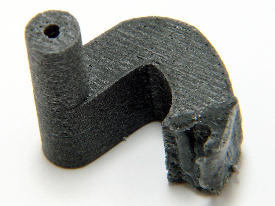
The “carbon fiber” part of PETG-CF consists of very very short fibers, unlike the longer fibers in real carbon fiber materials, so the strength is nowhere near what you might expect from the marketing. I knew this going in and the break wasn’t surprising.
The humidifier that Came With The House™ had a lid with two broken plastic hinges that I figured I could never replace, but while cleaning out the fuzz for the upcoming season I found one missing piece stuck inside the lid. Given a hint, I glued it back in place:
Humidifier Hinge – outlined
There’s a strip of duct tape around the outside holding the fragment in place while the adhesive cured.
A manual curve fit to the image in Inkscape produced the red outline, which gets saved as a plain SVG and fed into OpenSCAD to create a solid model:
Humidifier Hinge – solid model
The cylinder doesn’t exactly fit the end of the hinge, but it’s close enough. The straightforward OpenSCAD code making that happen:
The pin has a hole for a M2 screw, but contemplation of the broken pieces suggested the pin wasn’t the weakest link, which later experience confirmed.
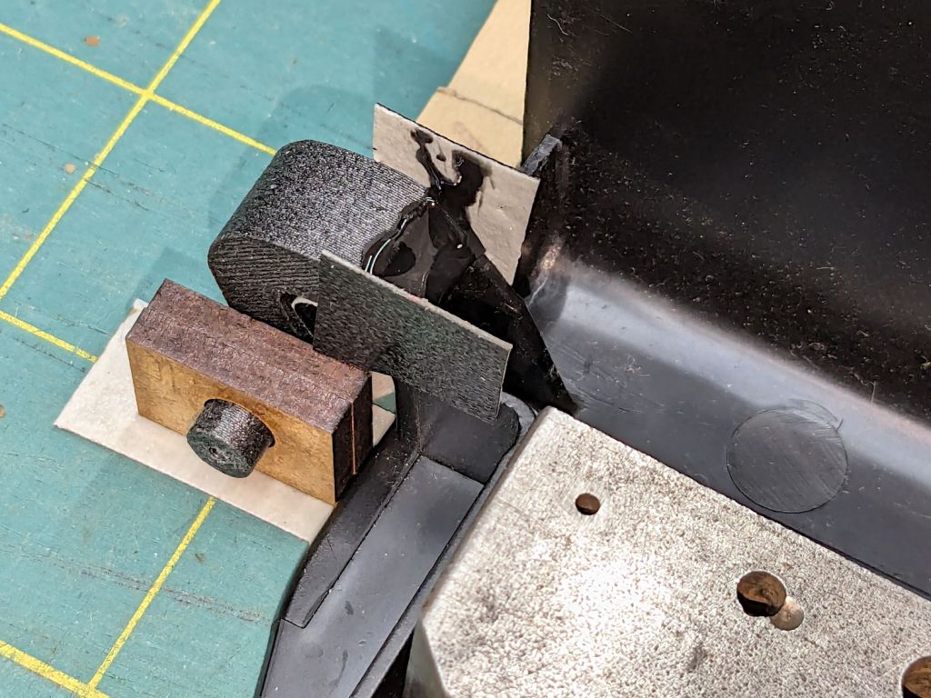
Figuring I’d need only one hinge, I made a spare for fitting:
Humidifier hinge – on platform
The unmodified part fit just about perfectly, whereupon a completely ad-hoc fixture involving a pair of laser-cut MDF slabs, a craft stick epoxy mixer, and more duct tape held it in place while the adhesive cured:
Humidifier hinge – fixturing
The hinge pin turned out to be half a millimeter too long, which is easily fixed, and it worked fine:
Humidifier hinge – installed
That’s more duct tape wrapped around the perimeter to hold the pieces in place, should it break again.
Which, I regret to report, occurred on the way up the stairs from the Basement Shop™ when the lid slipped from my grasp, fell away from the rest of the humidifer’s top panel, and jammed open:
Humidifier hinge – break
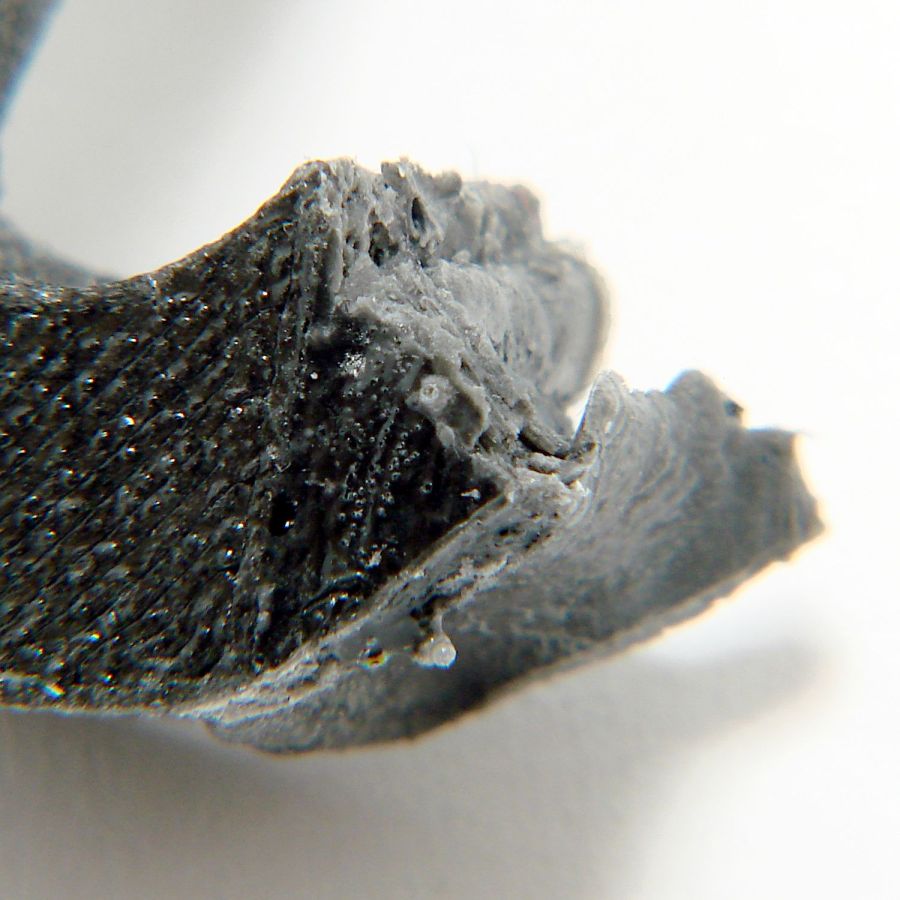
The PETG-CF part held together, the adhesive remained bonded to both pieces, but the original plastic fractured just below the joint. A closer look from the other side shows the break:
Humidifier hinge – break detail
The other hinge broke about where it did before.
So the humidifier remains in service with the lid in status quo ante and a small bag inside holding the fragments for the next return to the shop.
The previous owners replaced the deck two years ago, but the contractor installed more than half the planks with the grain cupped upward. The job was so bad the contractor replaced the most egregiously warped planks (over by the door and out of sight on the right) under warranty, but left all the other mis-oriented planks in place, presumably because they weren’t that bad yet.
The bare wood must age for a while before staining, so the shelf of painting supplies held a year-old gallon can as a reminder, with about two inches of stain / preservative in the bottom. I applied it to the “new” planks with pleasing results that absolutely do not match the rest of the weathered wood. With nothing to lose and plenty to gain, I applied the rest of the potion to the worst of the upside-down planks, producing the egregiously bad result you see above.
Given how the stain weathered to oblivion over the course of the last year, I expect all those planks will become roughly the same shade of ugly by next summer, when I might possibly be motivated to slather another gallon over the deck.
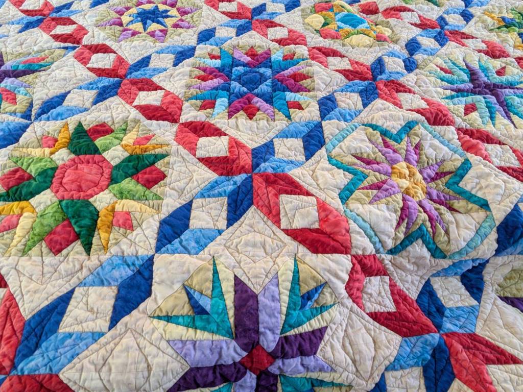
Mary recently finished a multi-year quilt project:
Dancine With The Stars quilt – detail
The overall pattern is “Dancing With The Stars” and it involves more intensive detail work than I have ever deployed on anything I’ve ever done:
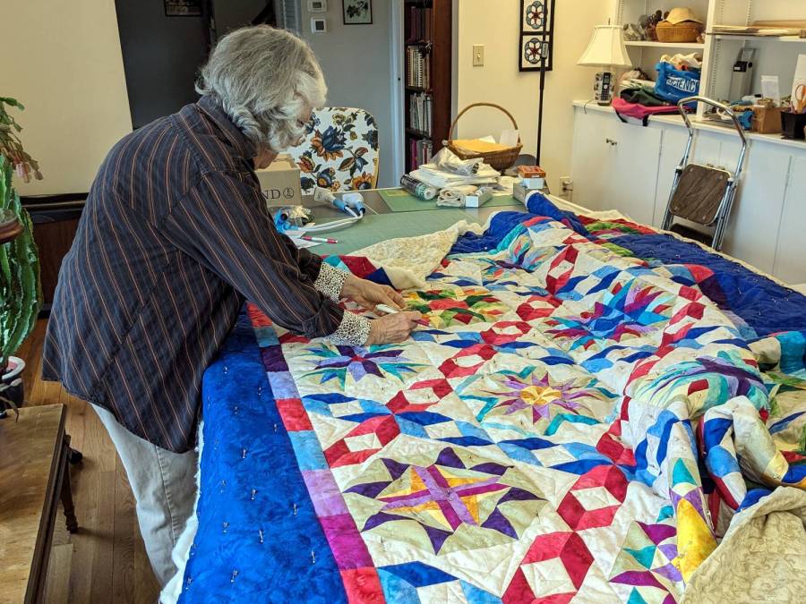
Mary with quilt on ping-pong table
Washing the quilt required a generous handful of Color Catchers to prevent the bold colors from bleeding into the lighter fabrics:
Dancing With The Stars quilt – color catchers
The sheets on the left came from the wash and the ones on the right came from a separate rinse cycle. We didn’t expect the “average” color to be brown, but there it is. We were both mightily relieved when they performed as expected!
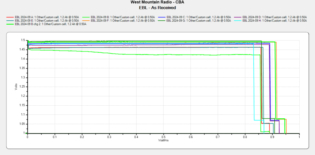
The cells claim 1200 mA·hr capacity, because it looks much more impressive than 1.2 A·hr, and deliver 900 mA·hr at 500 mA, likely higher than the scale’s actual load current.
Long years ago, the Bakelite (or some such) lid on our rarely used teapot disintegrated, whereupon I replaced it with an aluminum sheet and metal knob. Admittedly, a metal knob was not the brightest idea I ever had, but it sufficed for a few uses over the intervening decades.
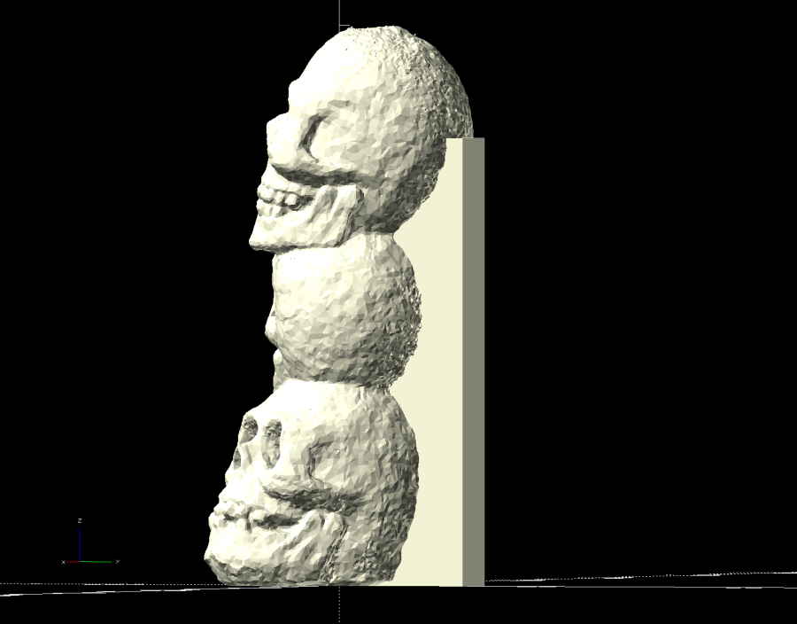
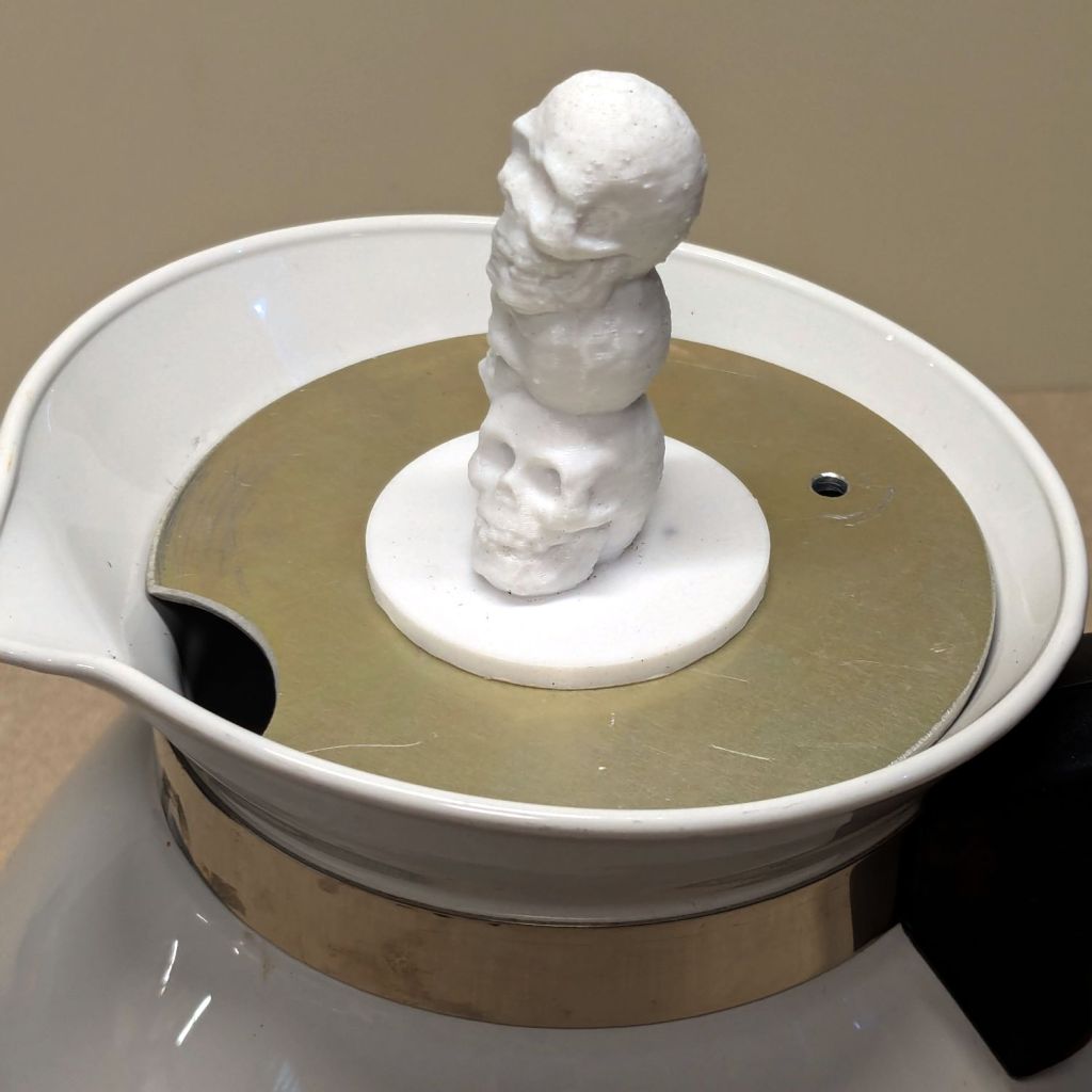
Mary hosted this month’s quilting bee and, after having someone else bring a larger teapot for the occasion, suggested I Make. A. Better. Knob. After a bit of searching, this statue seemed appropriate for the season:
Skull teapot knob
It’s printed with PETG filament that should easily withstand the no-more-than-boiling-water temperatures found atop a teapot.
I imported the original model into PrusaSlicer, shrank it to 50 mm tall and simplified the mesh, exported it as an OBJ file, imported it into OpenSCAD, mashed it together with a 1/4-20 threaded_nut from BOSL2, added the finger protector, and got a suitable model:
Teapot Knob – solid model bottom view
The as-printed threads were a bit snug with $slop=0, but running the screw in with a dot of silicone grease to ease the way worked fine.
I should rebuild the whole lid in PETG-CF sometime.