Ed Nisley's Blog: Shop notes, electronics, firmware, machinery, 3D printing, laser cuttery, and curiosities. Contents: 100% human thinking, 0% AI slop.
I got an Alead / Nolan HearLinks (many adjectives) Telecoil receiver to boost my ability to hear music & presentations at Vassar, because they recently slotted telecoil loops into the floors of their public venues. It took a few concerts to get the appropriate volume setting, after which I wondered how sensitive the receiver was:
Alead T-coil receiver – test setup
The small T in the upper right corner marks the receiving coil location, with the coil oriented parallel to the body’s long axis. It’s the secondary winding of an air-core transformer with a single-turn (perhaps using Litz wire) primary embedded in the floor, with the induced voltage obeying the usual transformer equation:
For a given installation and receiver position, pretty much everything is fixed, with the voltage depending only on the H field caused by the primary winding current.
The induced voltage is linearly dependent on the frequency, but the transmitter equalization filters apparently flatten the spectrum to get equal receiver amplitude between about 100 Hz and 5 kHz.
The coil in that picture has nine turns, with four passing through the Tek current probe. Applying 10 mVpp to the winding produces a corresponding current:
JDS6600 10mVpp 1 kHz – 4 turns – 1 mA-div
The scope sees 14 mVpp = 1.4 div at 1 mA/div = 1.4 mA. Dividing by 4 turns means the coil actually carryes 350 µA. The signal generator has a 50 Ω output impedance, so 10 mV should produce about 200 µA, which seems a bit low. On the other paw, the signal generator sees the coil as a dead short at 1 kHz, so I don’t trust the numbers.
Whatever magnetic flux it may be produces a 1 kHz tone at a somewhat higher volume (for the same receiver setting) than the fancy Vassar loops, so the flux is in the right ballpark. With a bit more attention to detail, perhaps I can tinker up a current-mode loop drive amplifier.
The Alead receiver has an internally generated tick audible at the audio volume I need for the Vassar loops, which is 5 to 7 steps down from the maximum volume at 15 steps. It seems related to the internal Bluetooth hardware, although it’s present even when the receiver is not paired with my Pixel phone and, in fact, is unchanged even when 100 feet from the nearest electronic device.
When I reported the problem, they said:
Yes, you can hear very minor tick sound on telecoil mode. It is caused by some electronic and current to make those tick sound. Sorry for this defective on the design.
It had one job that it doesn’t do well, so it’s on the way back for a refund.
Evidently, I must build an audio loop receiver to get what I want …
The display on Mary’s Cateye Astrale “Cyclocomputer” had once again faded to gray, so it’s time for a new CR2032 lithium cell:
Cateye Astrale – battery change 2019-09-22
The old cell read 2.5 V, well below what it should be.
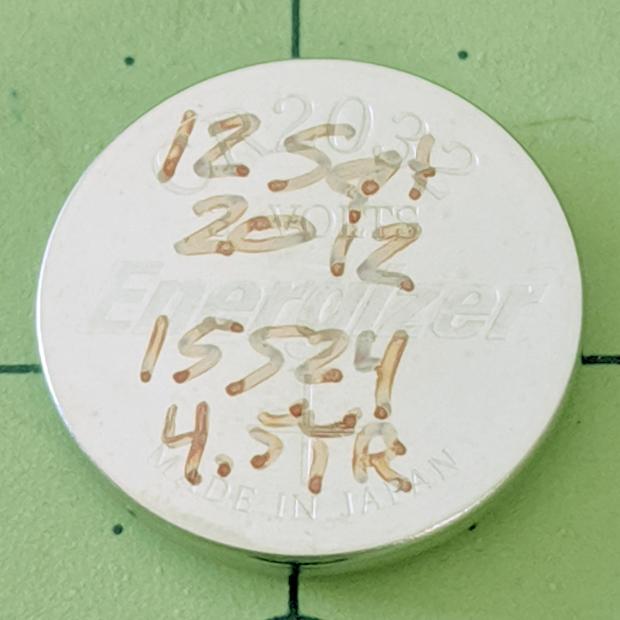
The notes scrawled on the cell become readable under better light:
Cateye Astrale – CR2032 life
Seven years (at 1942 mile/yr) ain’t bad at all!
To replace the cell fast enough to maintain the odometer reading, just unscrew & remove the battery cover, slam the back of the Astrale on the bench, and pop in the new cell.
Maybe I should replace the cell twice a decade, regardless of how feeble it might be?
Having previously concluded running the CNC 3018-Pro steppers from 12 V would let the DRV8825 chips provide better current control in Fast Decay mode at reasonable speeds, I wondered what effect a 24 V supply would have at absurdly high speeds with the driver in 1:8 microstep mode to reduce the IRQ rate.
So, in what follows, the DRV8825 chip runs in 1:8 microstep mode with Fast Decay current control. You must apply some hardware hackage to the CAMTool V 3.3 board on the CNC 3018-Pro to use those modes.
In all the scope pix, horizontal sync comes from the DRV8825 Home pulse in the top trace, with the current in the two windings of the X axis motor in the lower traces at 1 A/div. Because only the X axis is moving, the actual axis speed matches the programmed feed rate.
Homework: figure out the equivalent two-axis-moving speed.
The 12 V motor supply works well at 140 mm/min, with Fast Decay mode producing clean microstep current levels and transitions:
3018 X – Fast – 12V – 140mm-min 1A-div
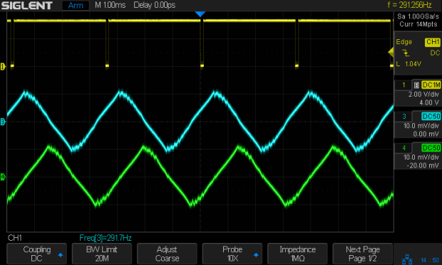
The sine waves deteriorate into triangles around 1400 mm/min, suggesting this is about as fast as you’d want to go with a 12 V supply:
3018 X – Fast – 12V – 1400mm-min 1A-div
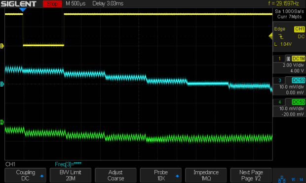
Although the axis can reach 3000 mm/min, it’s obviously running well beyond its limits:
3018 X – Fast – 12V – 3000mm-min 1A-div
The back EMF fights the 12 V supply to a standstill during most of the waveform, leaving only brief 500 mA peaks, so there’s no torque worth mentioning and terrible position control.
Increasing the supply to 24 V, still with 1:8 microstepping and Fast Decay …
At a nose-pickin’ slow 14 mm/min, Fast Decay mode looks rough, albeit with no missteps:
3018 X – Fast – 24V – 14mm-min 1A-div
At 140 mm/min, things look about the same:
3018 X – Fast – 24V – 140mm-min 1A-div
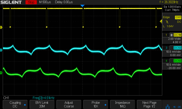
For completeness, a detailed look at the PWM current control waveforms at 140 mm/min:
3018 X – Fast detail – 24V – 140mm-min 1A-div
The dead-flat microstep in the middle trace happens when the current should be zero, which is comforting.
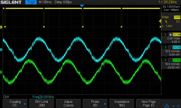
At 1400 mm/min, where the 12 V waveforms look triangular, the 24 V supply has enough mojo to control the current, with increasing roughness and slight undershoots after the zero crossings:
3018 X – Fast – 24V – 1400mm-min 1A-div
At 2000 mm/min, the DRV8825 is obviously starting to have trouble regulating the current against the increasing back EMF:
3018 X – Fast – 24V – 2000mm-min 1A-div
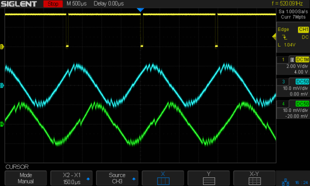
At 2500 mm/min, the back EMF is taking control away from the DRV8825:
3018 X – Fast – 24V – 2500mm-min 1A-div
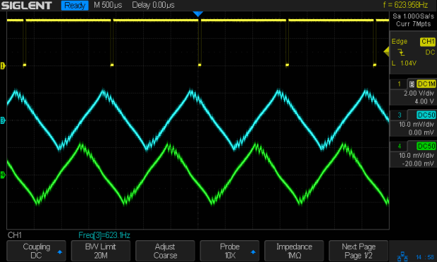
The waveforms take on a distinct triangularity at 2700 mm/min:
3018 X – Fast – 24V – 2700mm-min 1A-div
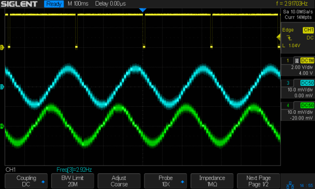
They’re fully triangular at 3000 mm/min:
3018 X – Fast – 24V – 3000mm-min 1A-div
In round numbers, you’d expect twice the voltage to give you twice the speed for a given amount of triangularity, because the current rate-of-change varies directly with the net voltage. I love it when stuff works out!
At that pace, the X axis carrier traverses the 300 mm gantry in 6 s, which is downright peppy compared to the default settings.
Bottom lines: the CNC 3018-Pro arrives with a 24 V supply that’s too high for the DRV8825 drivers in Mixed Decay mode and the CAMTool V3.3 board’s hardwired 1:32 microstep mode limits the maximum axis speed. Correcting those gives you 3000 mm/min rapids with good-looking current waveforms.
I’m reasonably sure engraving plastic and metal disks at 3000 mm/min is a Bad Idea™, but having some headroom seems desirable.
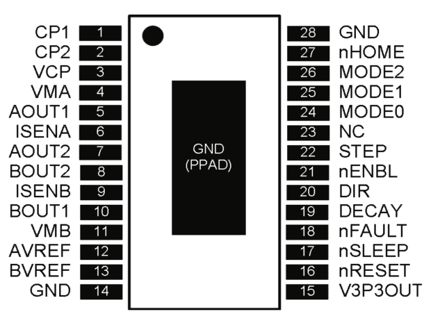
The DRV8825 stepper driver chip has a -Home output going active during the (micro)step corresponding to 45°, where both winding currents equal 71% of the peak value:
DRV8825 pinout
Unfortunately, pin 27 is another unconnected pin on the DRV8825 PCB, without even a hint of a pad for E-Z soldering.
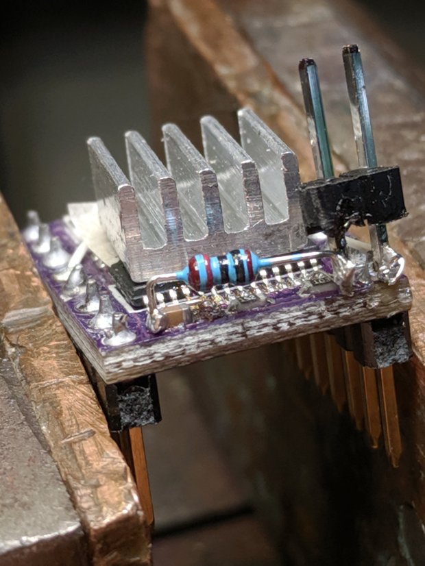
It’s also an open-drain output in need of a pullup, so I globbed on a 1/8 W 10 kΩ resistor in addition to the tiny wire from the IC pad to the left header pin:
DRV8825 PCB – Home signal output
Read it from the right: brown black black red gold. Even in person, the colors don’t look like that, not even a little bit: always measure before installation!
The right header pin is firmly soldered to the PCB ground pin I also used for the 1:8 microstep hack. The whole affair received a generous layer of hot melt glue in the hope of some mechanical stabilization, although hanging a scope probe off those pins can’t possibly end well.
The general idea is to provide a scope sync output independent of the motor speed, so I can look at the current waveforms:
3018 X – Fast – 12V – 140mm-min 1A-div
The alert reader will note the pulse occurs on the down-going side of the waveforms, which means I have the current probes clipped on backwards or, equivalently, on the wrong wire. The point is to get a stable sync, so it’s all good no matter which way the current goes.
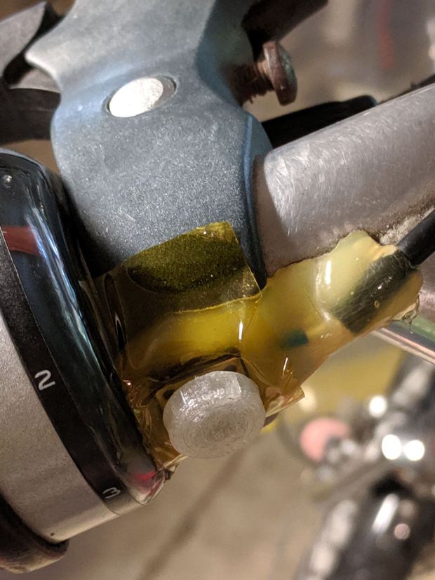
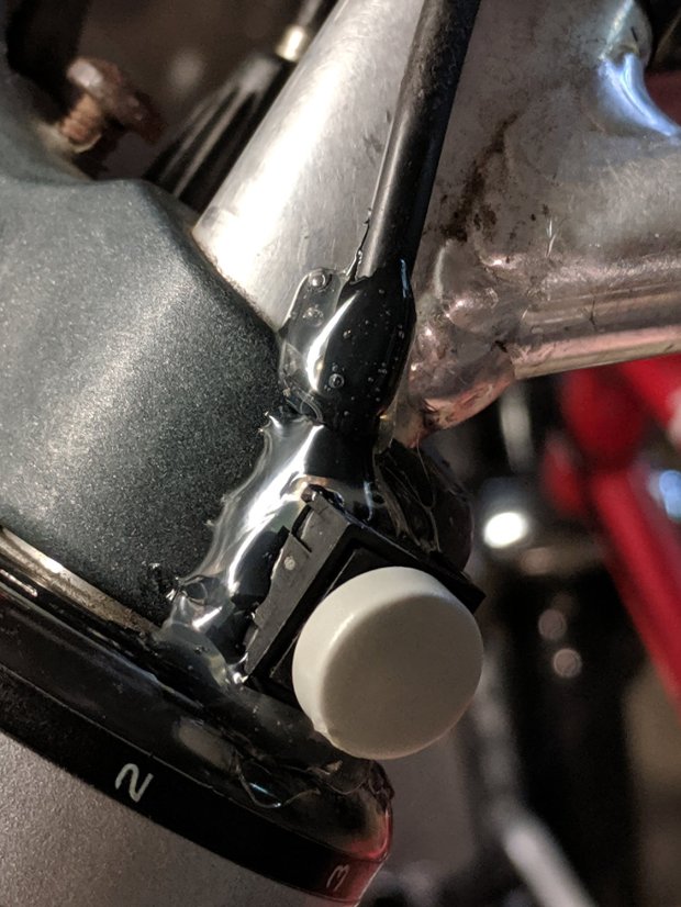
It’s been sitting there for least five years, as witnessed by the sun-yellowed hot melt glue blob, which is pretty good service from a switch intended for indoor use. The 3D printed button never fell off and, in fact, was difficult to remove, so that worked well.
I took it apart and cleaned the contacts, but to no avail, so her bike now sports a new switch with a similar rounded dome:
Tour Easy – new PTT switch
I clipped the wires a bit beyond the terminals and soldered the new switch in place, so it’s the same cable as before.
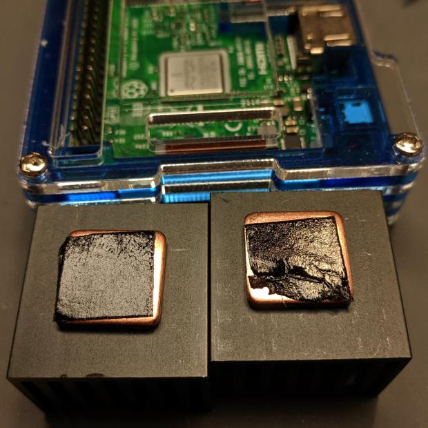
Unfortunately, the thermal tape on one of the CPU heatsinks was sufficiently wrinkled to prevent good contact with the CPU:
RPi taped heatsinks – as received
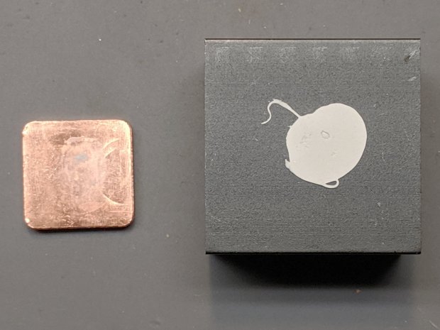
The seller sent a replacement copper slug with tape on one side. Presumably, they glue it to the heatsink with thermal silicone:
Moster RPi Heatsink – silicone adhesive
Of which, I have none on hand.
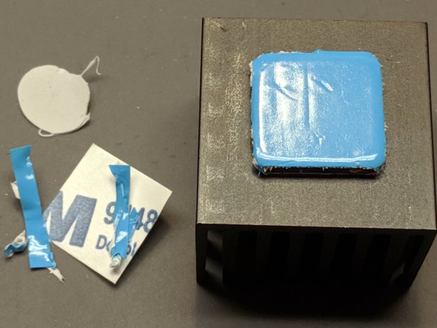
So I did what I should have done originally, which was to drop a few bucks on a lifetime supply of thermally conductive heatsink tape, apply it to the bare side of the slug and stick the slug to the heatsink with their tape:
Moster RPi Heatsink – replacement adhesive tape
The blue stuff is the separation film, with the tape being white. It doesn’t match the black tape on the other side, but seems gooey enough to work.
Done!
Despite the heatsink hype, ball grid array chips dissipate most of their heat through their pads (and perhaps a central thermal pad) into the PCB, so sticking a heatsink atop the package is largely decorative, along the lines of hotrod ornamentation.
The epoxy packages used in previous Raspberry Pi iterations had better thermal conductivity to their top surface:
RPi 3 B – epoxy CPU
Than the more recent metal-top packages, which surely have inert-gas fill under the lid:
Yes, the heatsink does conduct some heat into the air, even if not nearly as much as you might want.
(*) I’m pretty sure “Moster” was a typo in the original eBay listing which took on a life of its own to become something of an unofficial trademark. All of the search results ship from Duluth, Georgia (USA), regardless of the nominal seller; feel free to draw your own conclusions.
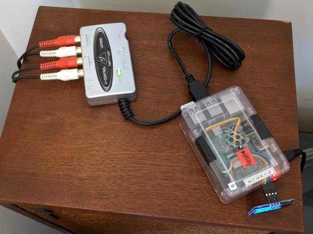
Fiddle with the amp to select the phonograph, poke the TAPE 2 button to send audio to/from the UCA202, fire up an SSH session, kill the streaming audio program, and figure out what audio hardware is out there:
$ arecord -l
**** List of CAPTURE Hardware Devices ****
card 1: CODEC [USB Audio CODEC], device 0: USB Audio [USB Audio]
  Subdevices: 1/1
  Subdevice #0: subdevice #0
Not much else to choose from on a Raspberry Pi, so see what the UCA202 can do:
Given those limited choices, 16 bit little-endian at 48 kHz seems like a no-brainer.
Find out all the ALSA device names:
$ arecord -L
null
    Discard all samples (playback) or generate zero samples (capture)
sysdefault:CARD=CODEC
    USB Audio CODEC, USB Audio
    Default Audio Device
front:CARD=CODEC,DEV=0
    USB Audio CODEC, USB Audio
    Front speakers
surround21:CARD=CODEC,DEV=0
    USB Audio CODEC, USB Audio
    2.1 Surround output to Front and Subwoofer speakers
surround40:CARD=CODEC,DEV=0
    USB Audio CODEC, USB Audio
    4.0 Surround output to Front and Rear speakers
surround41:CARD=CODEC,DEV=0
    USB Audio CODEC, USB Audio
    4.1 Surround output to Front, Rear and Subwoofer speakers
surround50:CARD=CODEC,DEV=0
    USB Audio CODEC, USB Audio
    5.0 Surround output to Front, Center and Rear speakers
surround51:CARD=CODEC,DEV=0
    USB Audio CODEC, USB Audio
    5.1 Surround output to Front, Center, Rear and Subwoofer speakers
surround71:CARD=CODEC,DEV=0
    USB Audio CODEC, USB Audio
    7.1 Surround output to Front, Center, Side, Rear and Woofer speakers
iec958:CARD=CODEC,DEV=0
    USB Audio CODEC, USB Audio
    IEC958 (S/PDIF) Digital Audio Output
dmix:CARD=CODEC,DEV=0
    USB Audio CODEC, USB Audio
    Direct sample mixing device
dsnoop:CARD=CODEC,DEV=0
    USB Audio CODEC, USB Audio
    Direct sample snooping device
hw:CARD=CODEC,DEV=0
    USB Audio CODEC, USB Audio
    Direct hardware device without any conversions
plughw:CARD=CODEC,DEV=0
    USB Audio CODEC, USB Audio
    Hardware device with all software conversions
They all point to the same hardware, so AFAICT the default device will work fine.
Try recording something directly to the RPi’s /tmp directory, using the --format=dat shortcut for “stereo 16 bit 48 kHz” and --mmap to (maybe) avoid useless I/O:
$ arecord --format=dat --mmap --vumeter=stereo --duration=$(( 30 * 60 ))  /tmp/Side\ 1.wav
Recording WAVE '/tmp/Side 1.wav' : Signed 16 bit Little Endian, Rate 48000 Hz, Stereo
                                  +02%|01%+                                   overrun!!! (at least 1.840 ms long)
                                  +02%|02%+                                   overrun!!! (at least 247.720 ms long)
                                +# 07%|06%##+                                 overrun!!! (at least 449.849 ms long)
                                 + 03%|02%+                                   overrun!!! (at least 116.850 ms long)
Huh. Looks like “writing to disk” sometimes takes far too long, which seems to be the default for MicroSD cards.
The same thing happened over NFS to the file server in the basement:
$ arecord --format=dat --mmap --vumeter=stereo --duration=$(( 30 * 60 ))  /mnt/part/Transfers/Side\ 1.wav

Recording WAVE '/mnt/part/Transfers/Side 1.wav' : Signed 16 bit Little Endian, Rate 48000 Hz, Stereo

                               +   09%|07%  +                                 overrun!!! (at least 660.372 ms long)

                                +# 08%|06%# +                                 overrun!!! (at least 687.906 ms long)
So maybe it’s an I/O thing on the RPi’s multiplexed / overloaded USB + Ethernet hardware?
Trying a USB memory jammed into the RPi, under the assumption it might be better at recording than the MicroSD Card:
$ arecord --format=dat --mmap --vumeter=stereo --duration=$(( 30 * 60 ))  /mnt/part/Side\ 1.wav
Recording WAVE '/mnt/part/Side 1.wav' : Signed 16 bit Little Endian, Rate 48000 Hz, Stereo
                                  +01%|01%+                                   overrun!!! (at least 236.983 ms long)
Well, if it’s overrunning the default buffer, obviously it needs Moah Buffah:
$ arecord --format=dat --mmap --vumeter=stereo --buffer-time=1000000 --duration=$(( 30 * 60 ))  /mnt/part/Side\ 1.wav
Recording WAVE '/mnt/part/Side 1.wav' : Signed 16 bit Little Endian, Rate 48000 Hz, Stereo
                               +## 10%|06%# +                                 overrun!!! (at least 359.288 ms long)
When brute force doesn’t work, you’re just not using enough of it:
$ arecord --format=dat --mmap --vumeter=stereo --buffer-time=2000000 --duration=$(( 30 * 60 ))  /mnt/part/Side\ 1.wav
Recording WAVE '/mnt/part/Side 1.wav' : Signed 16 bit Little Endian, Rate 48000 Hz, Stereo
                                  +00%|00%+
Sampling four bytes at 48 kHz fills 192 kB/s, so a 2 s buffer blots up 384 kB, which seems survivable even on a Raspberry Pi.
The audio arrives at 11.5 MB/min, so an LP side with 20 min of audio will require about 250 MB of disk space. The USB memory was an ancient 2 GB card, so all four sides filled it halfway:
$ ll /mnt/part
total 1.1G
drwxr-xr-x  2 ed   root 4.0K Dec 31  1969  ./
drwxr-xr-x 17 root root 4.0K Jun  7 19:15  ../
-rwxr-xr-x  1 ed   root 281M Sep  1 14:38 'Side 1.wav'*
-rwxr-xr-x  1 ed   root 242M Sep  1 15:01 'Side 2.wav'*
-rwxr-xr-x  1 ed   root 265M Sep  1 15:27 'Side 3.wav'*
-rwxr-xr-x  1 ed   root 330M Sep  1 15:58 'Side 4.wav'*
Side 4 is a bit longer than the rest, because I was folding laundry and the recording stopped at the 30 minute timeout after 10 minutes of silence.
Now, to load ’em into Audacity, chop ’em into tracks, and save the lot as MP3 files …