Ed Nisley's Blog: Shop notes, electronics, firmware, machinery, 3D printing, laser cuttery, and curiosities. Contents: 100% human thinking, 0% AI slop.
The DC motor used on the MK5 Extruder head seems unusually prone to sudden death, either by mechanical failure or something electrical. A stalled or shorted DC motor becomes a low resistance that destroys the A3977 H-bridge driver chip on the Extruder Controller board.
The power resistor reduces the voltage available to the motor, which draw something like 40 mA when unloaded and up to maybe 250 mA at full load. I don’t know what load the extruder puts on it, but at 100 mA the resistor drops 1 V, which seems excessive.
The relays seem like a nice solution, but they go clickety-clack and require actually building something, of which I’ve had quite enough lately, thank you very much.
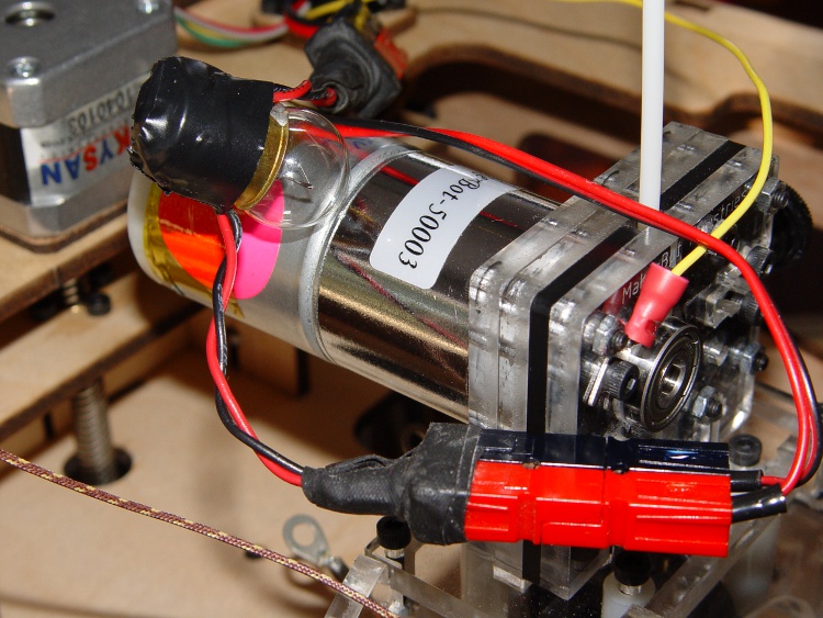
While I was mooching those lugs, my buddy Eks suggested simply putting a low-wattage 12 V incandescent lamp in series with the motor. The cold filament has a very low resistance, but limits the current when if the motor shorts out.
Extruder motor with series #89 bulb
A bit of rummaging in the Lamp Box produced an old automotive #89 lamp that allows 560 mA into a dead short, which works out to 7 W.
If the motor draws 100 mA, it drop only 100 mV: good enough!
Not finding a suitable socket in the heap, I wired it in by soldering the wires directly to the brass shell and central solder tip and taping up the mess. Next time I get near the local AutoZone I’ll pick up a socket.
The Anderson Powerpoles may look like overkill, but they make life a lot easier when you’re fiddling with the machinery all the time.
Now, the lamp won’t prevent inductive transients from blowing away those puny signal-level Zener diodes that should protect the A3977 chip, but it’s exactly what you need for long-term overload prevention.
Having collected useful thermal numbers at low power levels, it’s time to fire that mother up and see what happens at temperatures around 200 °C. That, however, requires powering both resistors, rather than attacking one with clip leads as I’ve been doing. Given that I expect to change the resistors several times in the course of this adventure, soldering to the lugs seemed like a lot of effort.
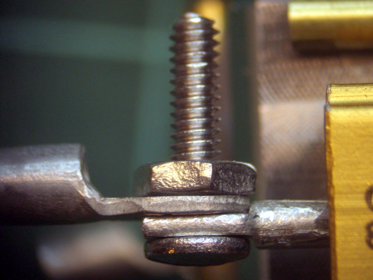
I mooched some solderless lugs suited for 2-56 screw terminals from Eks, pulled off the plastic insulating sleeves, lightly crimped them on 14 AWG solid copper wire, and silver-soldered the joints. The crimp handles most of the current, while the solder keeps the interior from accumulating oxidation products at high temperatures: a gas-tight joint is a happy joint.
Crimped and soldered lug
The resistor leads have holes just slightly too small for 2-56 screws, but a pass with a #41 drill does the deed; I think it’s an accumulation of solder rather than an under-sized hole.
The leads are stamped to shape and two of them didn’t have quite enough room for the lug. You don’t want the joint to look like this:
Misaligned lug
The briefest touch of a riffler file made them right, so as to look like this:
Properly aligned lug
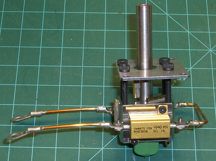
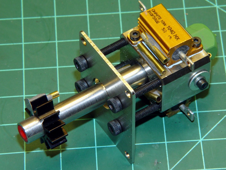
Then it was ready for insulation:
Extruder Head with lugs
Note that the resistors are in series, not parallel (as per the Makerbot instructions), because I want a resistor failure to produce an unambiguous symptom: no heat. In addition, I expect to operate the heaters at much lower power, making higher resistances easier to drive from the +12 V.
In truth, those screw-and-nut connections aren’t the most durable or reliable joints, particularly without lockwashers under the nuts to soak up the differential thermal expansion. But they’re good enough for what’s coming next.
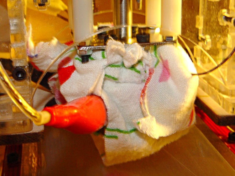
This test determines the effect of thermal compound between the resistor and the Thermal Core on the MK5 Extruder head. The setup is essentially the same as before, with cotton fabric insulation wrapped around the Core.
I applied a thin layer of Thermalloy Thermalcote II from a small bottle that I’ve had since the days when you could actually use trichloroethylene as a solvent. It’s rated to 200 °C, so it won’t last long at full throttle, but it’s not nearly as permanent as epoxy.
That’s the thin blue line around the base of the resistor. You can actually have too much of the stuff, so I applied this by rubbing a dab from a scrap of paper onto the resistor’s base and squooshing it in place.
Resistor with thermal compound
The instrumentation is the same as the last time around:
Name
Meter
Location
TOM
MK5 t-couple
Top of core
T1
Fluke 52
Resistor
T2
Fluke 52
Core edge adjacent to resistor
CA
Craftsman A
Bottom of core
CB
Craftsman B
not used
MPJA
MPJA meter
not used
After once again wrapping the core up in cotton cloth, I skipped directly to the higher power levels and sampled the data at 20-minute intervals.
Notice that the T2 reading on the block starts out a bit higher than the T1 reading on the resistor; I didn’t wait quite long enough for the heat of my hands to settle out inside that insulating blanket.
The corresponding temperature differences:
Power
R – Edge
Top – Bot
Edge – Top
Edge – Bot
R – Amb
Edge – Amb
0
-1.3
-0.1
0.1
0.0
0.0
0.0
4
3.1
2.9
1.0
3.9
51.6
47.2
4
3.1
4.3
-0.2
4.1
66.2
61.8
4
3.1
4.6
-0.6
4.0
71.1
66.7
4
3.0
4.5
-0.3
4.2
72.3
68.0
6
4.6
6.0
0.1
6.1
97.5
91.6
6
4.6
6.2
-0.3
6.0
103.4
97.6
6
4.5
6.7
-0.5
6.1
105.2
99.4
And now for the long-awaited and much anticipated thermal coefficients of the insulated and greased Thermal Core:
R – Edge
Top – Bot
Edge – Top
Edge – Bot
R – Amb
Edge – Amb
4 W
0.8
1.1
-0.1
1.0
18.1
17.0
6W
0.8
1.1
-0.1
1.0
17.5
16.6
The grease reduces the thermal coefficient by about 20%, although I admit the numbers going into that calculation are getting pretty close to the limits of my instrumentation. Assuming the value remains the same at 30 W, the resistors will rise about 24 °C above the Thermal Core temperature to 250 °C, their maximum rated temperature. At that temperature, remember, their maximum rated dissipation is 10% of their 25 °C value: a whopping 1 W.
The R – Ambient and Edge – Ambient coefficients show that the insulation has about the same effect as before, which is comforting.
Having found the thermal coefficient between the MK5 Extruder’s resistor and Thermal Core without any insulation wrapped around them, the next step is to do the same thing with insulation. In an ideal situation, the coefficient wouldn’t change: the same power flowing through the same area should produce the same effect. In actual practice, it decreases because the Core receives heat from the resistor that doesn’t pass through the interface.
I used the left-side resistor for this test, as the clip lead dislodged the brass tube atop the other one during the previous test.
Thermocouples locations – insulated
I used cotton fabric (harvested from an old sheet in the Rag Box) rather than the delicate ceramic cloth tape normally used with the MK5 head; I figured that plenty of cloth would be at least as good, as long as I didn’t run the temperature up all the way.
Cloth insulation – first wrap
A second wrap around the outside pretty much mummified the Thermal Core. Apart from a few small gaps & cracks, the only paths for heat to get out are the Thermal Tube and the four screws. There’s no ABS filament in the extruder head and the cloth covers the nozzle on the bottom.
Cloth insulation – final wrap
I didn’t instrument the Core quite so thoroughly, having already established that the metal Core block is pretty much isothermal.
The temperature differences between interesting points is:
Power
R – Edge
Top – Bot
Edge – Top
Edge – Bot
R – Amb
Edge – Amb
0
-0.3
-0.5
0.3
-0.3
0.0
0.0
1
1.5
-0.4
0.9
0.5
9.8
8.0
1
0.3
-0.6
1.3
0.7
13.2
12.6
1
1.0
0.8
-0.1
0.7
16.8
15.4
1
0.9
0.2
0.7
0.9
18.5
17.3
1
1.0
0.2
0.7
0.9
19.7
18.4
2
2.5
-1.9
1.4
-0.5
29.2
26.4
2
2.3
1.7
0.3
2.0
33.2
30.6
2
2.2
1.0
0.6
1.6
35.5
33.0
2
2.0
1.0
1.2
2.2
36.9
34.6
4
4.9
1.9
1.8
3.6
55.2
50.0
4
4.5
2.5
1.0
3.6
62.5
57.7
4
4.4
2.8
0.9
3.7
66.4
61.7
4
4.1
3.8
0.3
4.1
68.7
64.3
4
4.0
3.2
0.8
4.0
70.3
65.9
4
3.9
3.1
0.9
4.0
71.3
67.0
6
6.8
4.5
1.1
5.6
90.2
83.1
6
6.5
5.2
0.8
6.0
96.9
90.1
6
6.4
4.5
1.5
5.9
100.6
93.9
6
6.2
4.9
1.3
6.2
102.3
95.9
6
6.1
4.9
1.3
6.1
103.3
96.9
And the corresponding thermal coefficients…
R – Edge
Top – Bot
Edge – Top
Edge – Bot
R – Amb
Edge – Amb
1 W
1.0
0.2
0.7
0.9
19.7
18.4
2 W
1.0
0.5
0.6
1.1
18.5
17.3
4 W
1.0
0.8
0.2
1.0
17.8
16.8
6 W
1.0
0.8
0.2
1.0
17.2
16.1
The R-to-Edge coefficient is down to 1 °C/W, but that still means the resistor temperature is far too high at 30 W dissipation.
The R-to-Ambient and Edge-to-Ambient coefficients are up much less than I expected: the insulation helps, but not a great deal. I think there’s plenty of energy going out the Thermal Tube toward the Filament Drive and Extruder Motor; as the Core insulation gets better, conduction along the Tube becomes a larger fraction of the loss.
One last test looms: what’s the improvement with thermal compound between the resistor and the Core?
The objective here is to determine the thermal coefficient between the resistors and the Thermal Core, with no thermal compound to fill the air gap, so we know how high the resistor temperature will get.
The Thermal Core sprouted many thermocouples:
Name
Meter
Location
TOM
MK5 t-couple
Front of core
T1
Fluke 52
Resistor
T2
Fluke 52
Core edge adjacent to resistor
CA
Craftsman A
Top of core
CB
Craftsman B
Bottom of core
MPJA
MPJA meter
Heatsink on thermal tube
TOM with meters
They’re positioned as shown here, with the Bottom thermocouple to the rear out of view. The ribbed black heatsink at the very top of the picture is a few millimeters below the acrylic base of the Extruder Filament Drive block.
Thermal test setup
Applying power from a bench supply produced these results, adjusted to the average value using the regression coefficients determined there. The measurements occur every ten minutes: the Core’s time constant is, mmm, languid.
Adjusted Data
Power
TOM
T1
T2
CA
CB
MPJA
0
20.5
20.9
21.3
21.1
22.3
21.0
1
27.9
30.4
28.8
28.9
29.0
22.7
1
32.1
33.7
32.2
32.2
32.3
24.8
1
33.2
35.6
34.1
33.9
34.0
26.5
1
34.2
36.3
34.8
34.4
34.5
27.0
2
41.6
45.4
42.3
41.6
41.2
29.7
2
44.7
48.2
45.1
44.4
44.5
31.4
2
45.8
49.1
46.0
45.5
45.0
31.9
2
46.8
50.5
47.5
46.6
46.1
33.0
4
59.5
67.2
60.8
59.4
58.3
36.8
4
65.8
72.1
66.1
64.4
63.3
40.6
4
67.9
74.3
68.6
66.6
65.5
43.3
4
67.9
75.0
69.2
67.7
66.1
44.4
8
81.6
92.0
83.5
81.6
79.4
49.3
8
86.9
(*)
88.9
86.6
83.8
52.5
The asterisk marks the spot where a clip lead shifted and dislodged the brass tube epoxied to the resistor. Of course, that’s one of the two absolutely vital temperature measurements, but so it goes. I was planning to stop at 8 W, anyway, because that’s about as much power as I wanted to apply to the resistor, as it exceeds the rated power for that temperature.
The boldified lines mark the measurements where the Core temperature has stabilized, where I defined “stabilized” to mean “hasn’t changed all that much since the last measurement”.
Some temperature differences between interesting locations on the Thermal Core, bearing in mind that the linear regression equations aren’t good for much below 1 °C, at best, so the tiny differences are mostly noise.
Temperature Differences
Power
R – Edge
Core T-B
Edge-Bot
Top-Heatsink
R – Amb
Edge – Amb
0
-0.4
-1.2
-1.0
0.1
0.0
0.0
1
1.7
-0.1
-0.2
6.2
9.5
7.4
1
1.5
-0.1
-0.1
7.4
12.8
10.9
1
1.4
-0.1
0.2
7.4
14.7
12.8
1
1.4
-0.1
0.3
7.4
15.4
13.5
2
3.1
0.5
1.1
11.9
24.5
20.9
2
3.1
-0.1
0.6
13.1
27.3
23.8
2
3.1
0.5
1.0
13.6
28.2
24.7
2
3.0
0.5
1.4
13.6
29.6
26.2
4
6.4
1.1
2.5
22.6
46.3
39.5
4
5.9
1.1
2.8
23.8
51.2
44.8
4
5.7
1.1
3.0
23.3
53.4
47.2
4
5.8
1.6
3.1
23.3
54.1
47.8
8
8.5
2.2
4.1
32.3
71.1
62.1
8
2.8
5.1
34.0
67.5
The Top – Heatsink column says there’s really not much temperature difference between the Core and the cute little heatsink on the Thermal Tube at the top. This is without any Core insulation, but it’s also at a a much lower Core temperature.
And now for the heart of the matter: the thermal coefficients, which are the temperature differences divided by the applied power. These are for the boldified lines above, where the temperatures have stabilized.
These are not, strictly speaking, correct, because the only interface where we know the applied power lies between the resistor and the Thermal Core. But we’ll do the best we can with what we have…
Thermal coefficients
R – Edge
Core T-B
Edge-Bot
Top-Heatsink
R – Amb
Edge – Amb
1 W
1.4
-0.1
0.3
7.4
15.4
13.5
2 W
1.5
0.2
0.7
6.8
14.8
13.1
4 W
1.5
0.4
0.8
5.8
13.5
12.0
The R – Edge column shows that the resistor-to-Core thermal coefficient hovers around 1.5 °C/W, which means dissipating 30 W in the resistor raises its temperature 45 °C above the Core. With the Core stabilized at 225 °C, the resistors run at 270 °C, far beyond their absolute maximum rating of 250 °C where the rated power drops to 1 W.
That’s why MK5 Extruder resistors fail at such a disturbing rate.
The next two columns show the relatively small temperature differences across the the Thermal Core iself: that steel block is pretty much isothermal, even with only a single resistor providing power to one side. That’s good news, of a sort: clamping the MK5 thermocouple anywhere on the Core will provide consistent results.
The Top – Heatsink coefficient declines as the power level rises, probably because of the hot air rising from the uninsulated Core.
The R – Amb and Edge – Amb columns shows that air is a pretty good insulator all by itself. If you apply 30 W to the resistor and extrapolate a 10 °C/W thermal coefficient, the resistor would reach something like 300 °C above ambient, even without insulation. Obviously, that wouldn’t work for long, but those are the numbers.
With the thermistors nestled all snug in their wells, I turned on the heat and recorded the temperatures. I picked currents roughly corresponding to the wattages shown, only realizing after the fact that I’d been doing the calculation for the 5 Ω Thing-O-Matic resistors, not the 6 Ω resistor I was actually using. Doesn’t matter, as the numbers depend only on the temperatures, not the wattage.
This would be significantly easier if I had a thermocouple with a known-good calibration, but I don’t. Assuming that the real temperature lies somewhere near the average of the six measurements is the best I can do, so … onward!
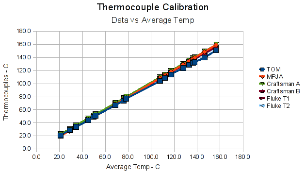
Plotting the data against the average at each measurement produces a cheerful upward-and-to-the-right graph:
Data vs Ensemble Average
So the thermocouples seem reasonably consistent.
Plotting the difference between each measurement and the average of all the measurements at that data point produces this disconcertingly jaggy result:
Difference from Ensemble Average
The TOM thermocouple seems, um, different, which is odd, because the MAX6675 converts directly from thermocouple voltage to digital output with no intervening software. It’s not clear what’s going on; I don’t know if the bead was slightly out of its well or if that’s an actual calibration difference. I’ll check it later, but for now I will simply run with the measurements.
Eliminating the TOM data from the average produces a better clustering of the remaining five readings, with the TOM being even further off. The regression lines show the least-squares fit to each set of points, which look pretty good:
Difference from Average without TOM
Those regression lines give the offset and slope of the best-fit line that goes from the average reading to the actual reading, but I really need an equation from the actual reading for each thermocouple to the combined average. Rather than producing half a dozen graphs, I applied the spreadsheet’s SLOPE() and INTERCEPT() functions with the average temperature as Y and the measured temperature as X.
That produced this table:
                    TOM     MPJA  Craftsman A  Craftsman B   Fluke T1  Fluke T2
M = slope        1.0534   0.5434       0.5551       0.5539     1.0112    1.0154
B = intercept   -1.6073 -15.3703     -19.4186     -16.9981    -0.7421   -0.3906
And then, given a reading from any of the thermocouples, converting that value to the average requires plugging the appropriate values from that table into good old
y = mx + b
For example, converting the Fluke 52 T1 readings produces this table of values. The Adjusted column shows the result of that equation and the Delta Avg column gives the difference from the average temperature (not shown here) for that reading.
The Max Avg Error (the largest value of the absolute difference from the average temperature at each point) after correction is 0.78 °C for this set. The others are less than that, with the exception of the TOM thermocouple, which differs by 1.81 °C.
So now I can make a whole bunch of temperature readings, adjust them to the same “standard”, and be off by (generally) less than 1 °C. That’s much better than the 10 °C of the unadjusted readings and seems entirely close enough for what I need…
The man with one thermometer knoweth the temperature
The man with many thermometers knoweth not the temperature
Drilling the isothermal block
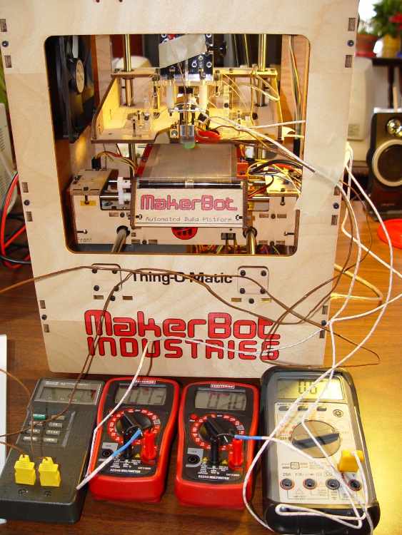
Given the five thermocouples and their meters shown there, plus the Thing-O-Matic’s thermocouple, I had six different temperatures. They’re close, but we can do better than that.
The general idea is to put all the thermocouple beads in close proximity so they share the same temperature, record their opinions to various temperatures, then figure out an equation that adjusts their disparate opinions to reflect consensus reality.
I cranked out an isothermal block on the Sherline mill, using EMC2’s exceedingly handy polar coordinate notation to get a nice hexagon. Touch off XYZ=0 at the middle of the block, then center-drill and drill:
For lack of anything better, 3000 rpm with a drill matching the ID of the brass tubes, plus dripping cutting fluid as needed.
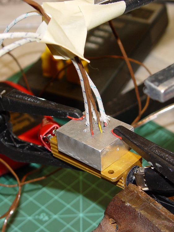
Thermocouples in block
I used a 6 Ω 50 W resistor (the adult version of the resistors on the Thing-O-Matic / MK5 head) as a heat source, clamping the block to the resistors with plastic clamps to provide mechanical force and thermal isolation. Good idea, bad implementation: as you’ll see, those little red tips melt at a rather low temperature.
The TOM thermocouple bead will fit into the empty hole.