Ed Nisley's Blog: Shop notes, electronics, firmware, machinery, 3D printing, laser cuttery, and curiosities. Contents: 100% human thinking, 0% AI slop.
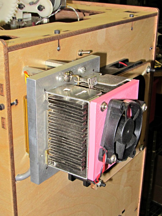
The fan on the dummy load that consumes the required minimum current to keep the ATX power supply happy wasn’t starting up reliably. That’s not surprising: I connected it to 5 V rather than the rated 12 V, because the load heatsink needs just a whisper of air flow to stay barely above room temperature, so it’s barely turning over and has no spare torque at all.
It turns out the heatsink really doesn’t need any forced air flow, despite having the fins oriented crosswise. Without the fan, it stabilizes just above comfortable-to-the-touch, a bit hotter than I’d prefer.
While I had the hood up for the HBP rebuild, though, I swapped in another fan and the heatsink is now cool to the touch. I did clean that dust off the fins, too.
If this one also fails at +5 V, I’ll fiddle the wiring to put it across the +12 V and +5 V supplies, where it’ll see 7 V. That should improve its disposition…
If you pick up consumer-grade UPS units during closeout sales, they cost little more than replacing the batteries in older units… so we now have a new UPS replacing an old Waber box.
Just for completeness, I pulled the 25 A internal fuses:
Waber UPS battery fuses
And then measured the remaining battery capacity:
Waber UPS
The pair of sealed lead-acid batteries claim 5 Ah each, so the 6 A load far exceeds the usual C/20 SLA test current. The fact that the better one hit 1.6 Ah under that load says it’s in surprisingly good shape.
In fact, the label I put on that battery in January 2008 says it hit 1.4 Ah at 2.5 A, so it’s doing much better than you’d expect.
However, the UPS claims to support 650 VA = 450 W at 0.7 power factor. The batteries must supply the real power while the inverter drives the reactive load; giving Waber the benefit of the doubt at 90% efficiency says the batteries must provide 500 W = 21 A at 24 V under full load.
The basic problem with the heater on the Heated Build Platform is that the SMD pads must both make electrical contact to the Molex-style connector and withstand mechanical stress from the dangling wires & cables as the platform moves along the X and Y axes. Rather than replace the entire heater, I attached pigtail leads to the PCB, anchored those leads to the wood platform under the heater, and routed the cables through the deck under the Y axis stage a bit differently.
However, attaching pigtail leads to the PCB poses a problem, because ordinary electronic hookup wire has thermoplastic insulation that melts or deforms at temperatures well under my usual 110 °C platform heat setting; shorting the heater wires would be a Very Bad Thing.
Some concerted rummaging in the Big Box o’ Multiconductor Cable turned up a hank of Teflon-insulated shielded two-wire cable that, as nearly as I can tell, has pure silver conductors and shield braid: the ends were tarnished like silver and there’s nary a trace of copper in the fresh cuts. It must be military surplus and, based on a vague recollection, was most likely cough salvaged by my father, who worked as an avionics tech at Olmstead AFB in the mid-60s. Ya gotta have stuff, right?
[Update: Alas, it’s not pure silver, as shown in the comments.]
The general idea is to scuff up the shiny PCB surface enough to anchor blobs of JB Industro Weld epoxy that surround brass tubes holding the cables. A pair of tubes secure each cable and provide strain relief; the cable is free to move, but not by very much. The thermistor cable has a long arch that will, I hope, keep the cable at the platform temperature and reduce its cooling effect on the thermistor:
Thermistor rewiring – heat cure
The alligator clips connect to a bench power supply that delivered 4 V @ 2 A = 8 W that heated the PCB to about 40 °C in the rather chilly Basement Laboratory and encouraged the epoxy to cure in less time than forever.
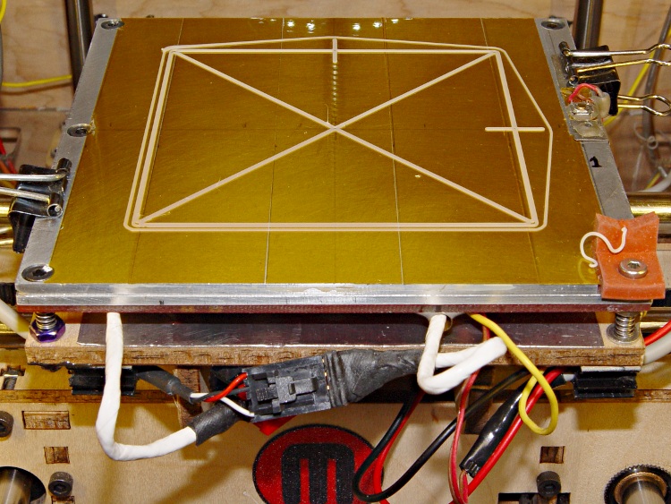
The final result looked like this, with Anderson Powerpoles now attached to the heater cable:
Rewired HBP
The 24 AWG conductors in the cable may seem scanty for 6 A of heater current, but, hey, they’re silver.
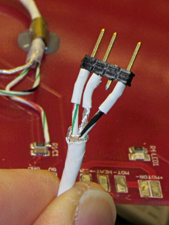
The three-pin connector on the end of the thermistor cable is a pure kludge, built from a 4-pin header to match the CD-ROM audio pinout on the new cable from the Extruder Controller. I kept the default pinout on this end to provide some protection against plugging it in backwards:
Kludged HBP thermistor connector
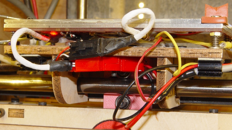
With all that in hand, I screwed the PCB to the aluminum sub-plate, bolted it to the plywood platform, and stuck the cables onto the platform with adhesive clamps:
Rewired HBP – front
Reaming out the hole between the red and black Powerpole shells provided just enough room for an M3 screw to anchor them to the HBP: they won’t flop around under acceleration.
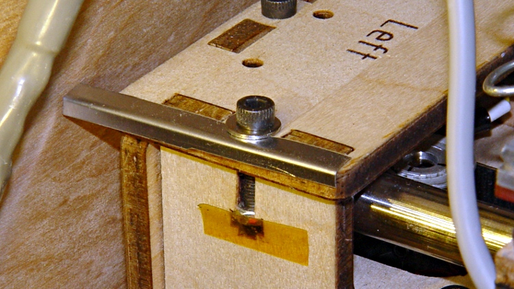
The thermistor cable exits to the left, the rest to the right, and I’m unhappy with the overall routing. I added a small bumper (made from bent steel shim stock) to keep the thermistor cable out of the gap between the Y axis stage and the left side wall:
The platform is holding level within ±0.05 mm across build plates 1 and 2, somewhat better than before. On the other paw, the whole thing doesn’t have many hours on it…
Given that the SMD pads fell off the HBP circuit board and I must replace the connector, I figured I may as well also replace the remarkably stiff MBI thermistor cable with a much more flexible CD-ROM audio cable. Although the EC end of the MBI cable looks like a standard CD-ROM audio connector, it’s been rewired. No problem: this is not an audio application and I’m going to do exactly the same thing.
The Extruder Controller, however, doesn’t have a matching connector and the recommended attachment involves simply jamming the connector onto the pin header, per this detail cropped from that photo in the MBI assembly instructions:
MBI EC HBP Thermistor Connector Alignment – Detail
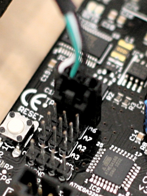
Here’s a better closeup of my EC, taken from the other side:
MBI Extruder Controller – HBP thermistor connector
The header block breaks out the Arduino’s Analog Input pins, with A6 in the front of that photo. From left to right, the pins under the HBP connector are A6 / +5 V / Gnd. Unfortunately, the connector wiring and alignment puts the thermistor signal on the cable shield, with the Gnd and +5 V wires safely tucked inside. This is, shall we say, suboptimal.
The Gnd connection provides a low-impedance connection to the least-noisy part of the circuit, so putting it on the shield tends to prevent the relatively high-impedance signals within from picking up noise. This isn’t always successful, for a number of reasons, but it’s a Good Idea.
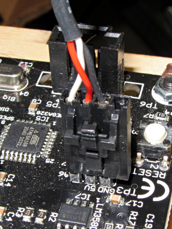
Although probably doesn’t make much difference (it’d just add a bit of noise to the HBP temperature signal), but if I’m going to be rewiring it anyway, the cable shield will be at ground potential with the signal wire inside. Here’s my cable & connector, rearranged to make that so:
EC HBP thermistor connector – revised
The analog audio connector on the back of old-school CD-ROM drives, back before digital audio output from the drives actually worked, had four pins:
Left (white) and Right (red) audio channels on the outer pair
Ground (black) on at least one of the central pair
So the red wire will be in the far right-hand socket of the connector shell; depress its locking tab, slide it out of the shell, poke it into the socket between the other two wires, push to click, and you’re set. Conveniently, this puts the +5 V supply on the red wire, which is sorta-kinda standard. Your cable colors may vary; pay attention to the actual wiring and ignore the color code!
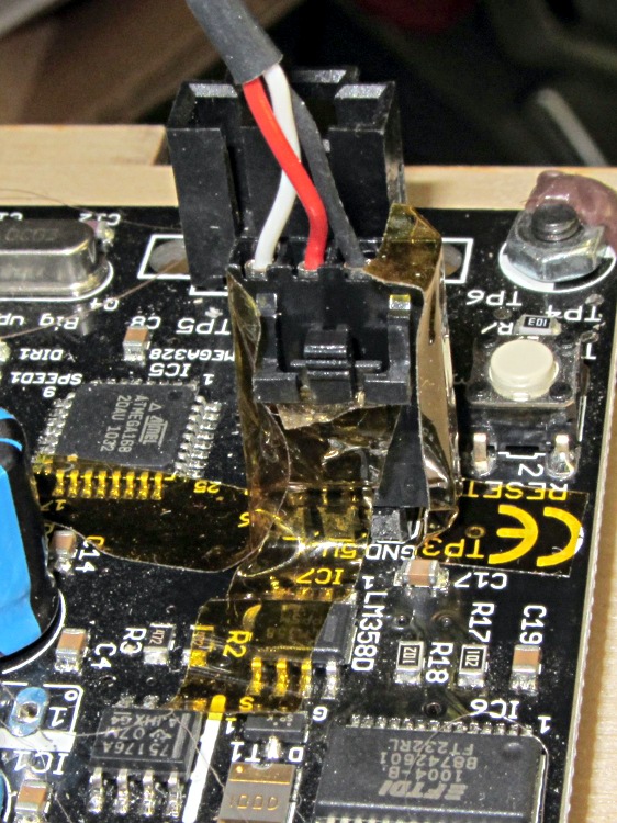
Tape the connector in place (with the empty socket now toward the board edge) to prevent the tangle of wires in the Thing-O-Matic’s electronics bay from dislodging it at an inopportune moment:
EC HBP thermistor connector – secured
Admittedly, that arrangement still tucks the +5V wire right next to the signal wire inside the shield, but it’s a step in the right direction.
You could flip the MBI cable around, too, as long as you also rearranged the pins at the HBP end to match.
This has been a long time coming, as the connector shell over that pin connecting the MOSFET to the heater has been getting crispier despite my attention, cleaning, and occasional DeoxIT application.
Burned-out HBP connector
Notice that the burned pin now stands at a slight angle to the others. The PCB pad has no additional copper traces on that side to conduct the heat away from the failing connection, so the joint got hot enough to put the solder into its semi-liquid state, whereupon the springy connector rammed it upwards through the softened plastic shell. If the PCB fab shop used 60-40 lead solder, that’s around 188 °C. Silver solder would reach 220-ish °C. If the solder was eutectic, it would turn liquid and just drip off.
What doesn’t show: the SMD pads that pulled free from the PCB surface, fortunately only under the rightmost three pins leading to the thermistor. Repairing the pads and connector makes no sense, so I think I’ll go with pigtail leads anchored to the plywood, with offboard connectors to reduce the strain on those pads. Powerpoles will be bulky, but maybe pigtails long enough to get them onto the case might work.
As a general rule, soldering wires or connectors to SMD pads with no mechanical support is a Bad Idea and applying repeated mechanical stress to those connectors is a Very Bad Idea. Doing all that on a PCB running well over 100 °C with current right up near the connector’s absolute maximum, well…
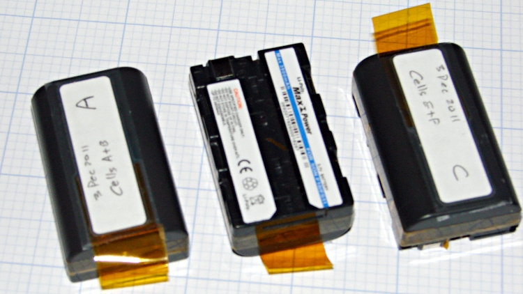
The batteries I rebuilt for our much-beloved Sony DSC-F505V camera back in early 2010 have faded away with constant use. Having already sawed the cases open, rebuilding three of them didn’t pose much of a challenge; this time I added a short tab of Kapton tape to help extract them from the camera socket.
Rebuilt NP-FS11 batteries
Three batteries seems to be about the minimax for ordinary use:
One in the camera
One in the carrying case
One in the charger
You (well, we) can’t keep track of more than three: it always seems one battery gets overused and another gets lost in the dark. We’ll see how three works in practice; there’s a set of six more raw cells lying in wait.
The new batteries produced these results on their first two charge-discharge cycles:
Sony NP-FS11 2011 Packs – First Charges
One battery didn’t come up to speed on the first charge, but after that they’re all pretty close.
These were cheap-after-rebate phones with 2/3 AA NiCd cells that lasted nigh onto five years. We rarely talk on the phone and even more rarely use these, so they’re on the dreaded continuous trickle charge and low usage cycle that kills rechargeable batteries. Of course, they’ve been sitting there for five years…
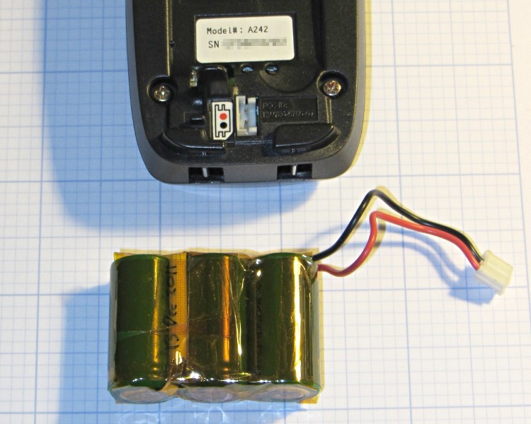
The rebuild was no big deal, although I had to replace the original 360 mAh NiCd cells with 650 mAh NiMH cells (with tabs) because that’s what’s available nowadays. The trickle rate will be even lower relative to the capacity, of course, which may or may not be a Bad Thing.
The packs contained a simple fuse consisting of a thinned section of the usual nickel strap connecting two cells, covered with a fiberglass sleeve under the shrink overwrap. For lack of anything smarter, I harvested the fuse and soldered it in the new pack. although the risk of a catastrophic short seems fairly low:
NiCd pack with thin-wire fuse
The final result looks about as you’d expect, complete with obligatory Kapton tape wrap:
Ativa phone – rebuilt battery
The old pack is kaput and new pack delivers pretty nearly its rated capacity at an arbitrary 550 mA discharge (which is, admittedly, a bit stiff for the old pack):
Ativa phone battery tests
That takes care of one phone… the other one’s probably in the same condition, so I have enough cells to rebuild it, too.