Ed Nisley's Blog: Shop notes, electronics, firmware, machinery, 3D printing, laser cuttery, and curiosities. Contents: 100% human thinking, 0% AI slop.
Until a month or two ago, when it began disconnecting randomly.
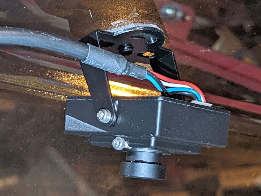
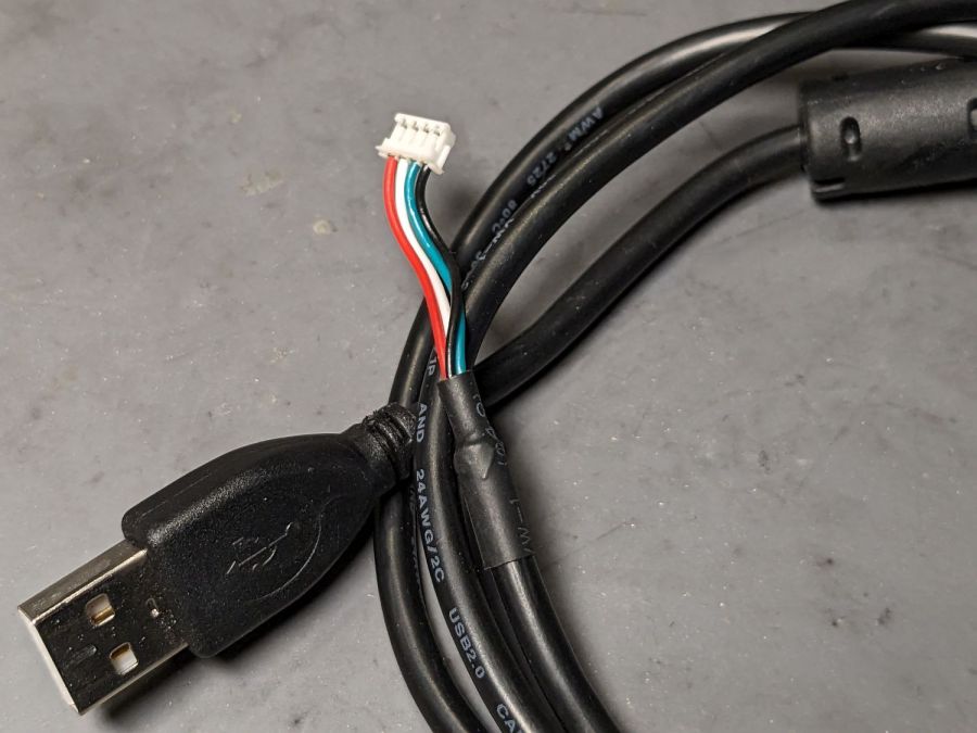
The camera cable has a standard USB A connector on one end and what looks like a 1.5 mm JST ZH connector on the other:
Laser cutter camera cable
Of course, it’s not quite long enough, so it plugs into a good-quality 1 meter USB 3.0 extender to the PC sitting atop the laser cabinet.
Some low-effort tweaks were unavailing:
Different USB ports
Different USB extension cable to the ports
Hub vs. direct
Eventually, some rummaging in the Box o’ USB Cables produced a cable from a different camera and, as you might expect, swapping the two identical cables solved the problem.
I have no idea what’s going on, but I’d lay significant money that when this cable gets flaky, swapping the original cable back in will solve the problem once again.
For reasons that will become relevant later on, I must clear the magazines from about ten feet of shelf space (and a stack of boxes), including this assortment:
To the best of my knowledge and belief, each collection is complete within those dates, although I’m equally sure an issue or two went walkabout over the course of four decades.
Having written columns for Digital Machinist, DDJ, and Circuit Cellar, I (still!) have multiple “author’s copies” of those, although I haven’t dug through the boxes for the specifics.
Here’s the deal:
You must take all of any set
Any offer ≥ $0.00 is acceptable
Shipping from ZIP 12603 is your problem
N.B.: Shipping Is Not My Problem (*)
Best offer on or before 30 November 2023 takes any or all.
Whatever remains becomes mulch in December 2023.
(*) A USPS Medium Flat Rate box (11×8.5×5.5 inch) costs $17 within the continental US and holds two or three dozen issues. Obviously, that’s the wrong way to ship an entire shelf of magazines, but gives you an idea of the scale.
If you want to pick ’em up in person, I’ll help heave ’em into your trunk.
Nuheara predicts two to three years of battery lifetime for their IQbuds² MAX not-really-hearing-aids and, indeed, after 2-½ years of more-or-less steady use, the right bud developed a bad case of not charging fully and discharging quickly. The batteries are not, of course, customer-replaceable, so one can:
Buy a single bud
Buy a complete new pair + case + accessories
Ask about their repair service
Unsurprisingly, a single bud costs more than half the cost of the full set and the repair service is a complete mystery. Given that the left bud’s battery will likely fail in short order, let’s find out what’s inside.
Your ear sees this side:
Nuheara IQbud – bottom view
The dark oval is a (probably IR) sensor telling the bud when it’s jammed in your ear.
Everybody else sees this side:
Nuheara IQbud – top view
The small slit over on the right and the two holes around the top seem to be for various microphones.
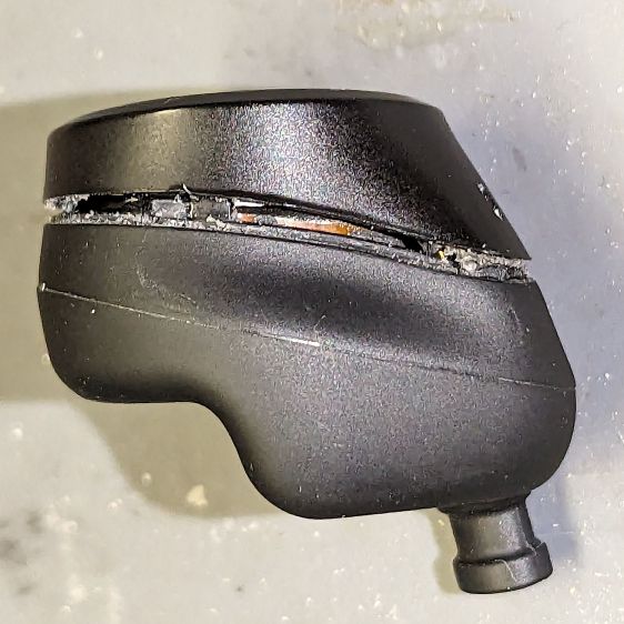
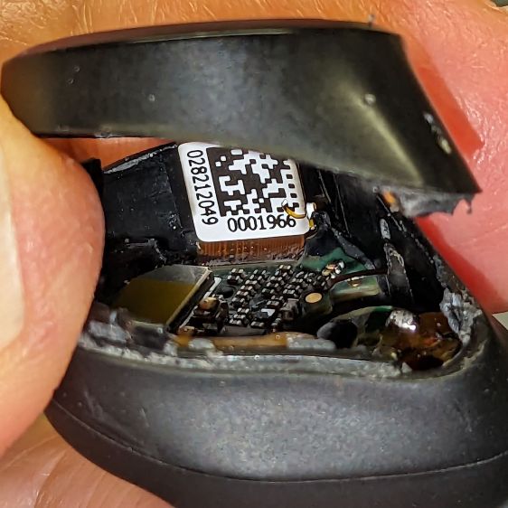
Jamming a plastic razor blade into the junction between the two parts of the case, just under the mic slit, and gently prying around the perimeter eventually forces the adhesive apart:
Nuheara IQbud – case splitting
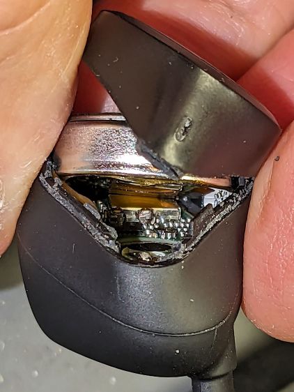
Do not attempt to yank the two pieces apart, because a ribbon cable joins the lower and upper PCBs:
Nuheara IQbud – ribbon cable
The metallic disk in the lower part is the lithium battery.
Ease the upper part away, being very careful about not tugging on the ribbon cable:
Nuheara IQbud – raising battery
The battery has moved upward, revealing the lower PCB.
Rolling the upper part toward the ribbon cable eventually produces enough space to extract the battery:
Nuheara IQbud – battery freed
Note the orientation:
The rebated end is the negative terminal and faces outward
The wider end is the positive terminal and faces inward
With the battery out, you can admire the PCBs and ribbon cable:
Nuheara IQbud – interior view
What is not obvious from the picture: two pairs of spring-loaded pogo pins contacting the battery. There is no actual battery holder, as it’s just tucked into the structure of the bud, with the perimeter adhesive providing the restraining force for the pogo pins.
The 1654 cells I got came with wire leads welded to the cell and a complete Kapton enclosure; apparently other devices use soldered connections rather than pins. They proudly proclaim their “Varta” heritage, but I have no way to prove they actually came from Germany.
I snipped off the wires, carved a pair of holes through their Kapton for the contact pins, tucked the cell in the bud, pressed the halves together, applied a clamp, then wrapped a strip of Kapton tape around the perimeter:
Nuheara IQbud – reassembled
It seems remarkably easy to wrap the tape over the front microphone, but don’t do that. Conversely, sealing the entire perimeter is the only way to prevent acoustic feedback, so I added a snippet of tape just under the front mic opening.
Do that for the other bud and declare victory.
That is, fer shure, not the most stylin’ repair you’ve ever seen, but I was (for what should be obvious reasons) reluctant to glue the halves together. I expect the tape to peel off / lose traction after a while, but I have plenty of tape at the ready. Worst case, I can glop some adhesive in there and hope for the best.
Because the buds lost power during their adventure, they required a trip through their charging case to wake them up again. After that, they work as well as they did before, with consistently longer run time from both buds.
The Moonlander keyboard has per-key LEDs that I’ve denatured enough that most show a pale gray, with a few others highlighted in orange. A few weeks ago the LEDs on the right-hand thumb cluster and the N key went nuts, cycling through a surprising assortment before settling on bright red; the obvious resets / firmware reflashing / tapping were all unavailing.
ZSA’s tech support recommended taking the thumb cluster apart to check the ribbon cable connecting it to the main keyboard half:
Moonlander thumb cluster – PCB bottom
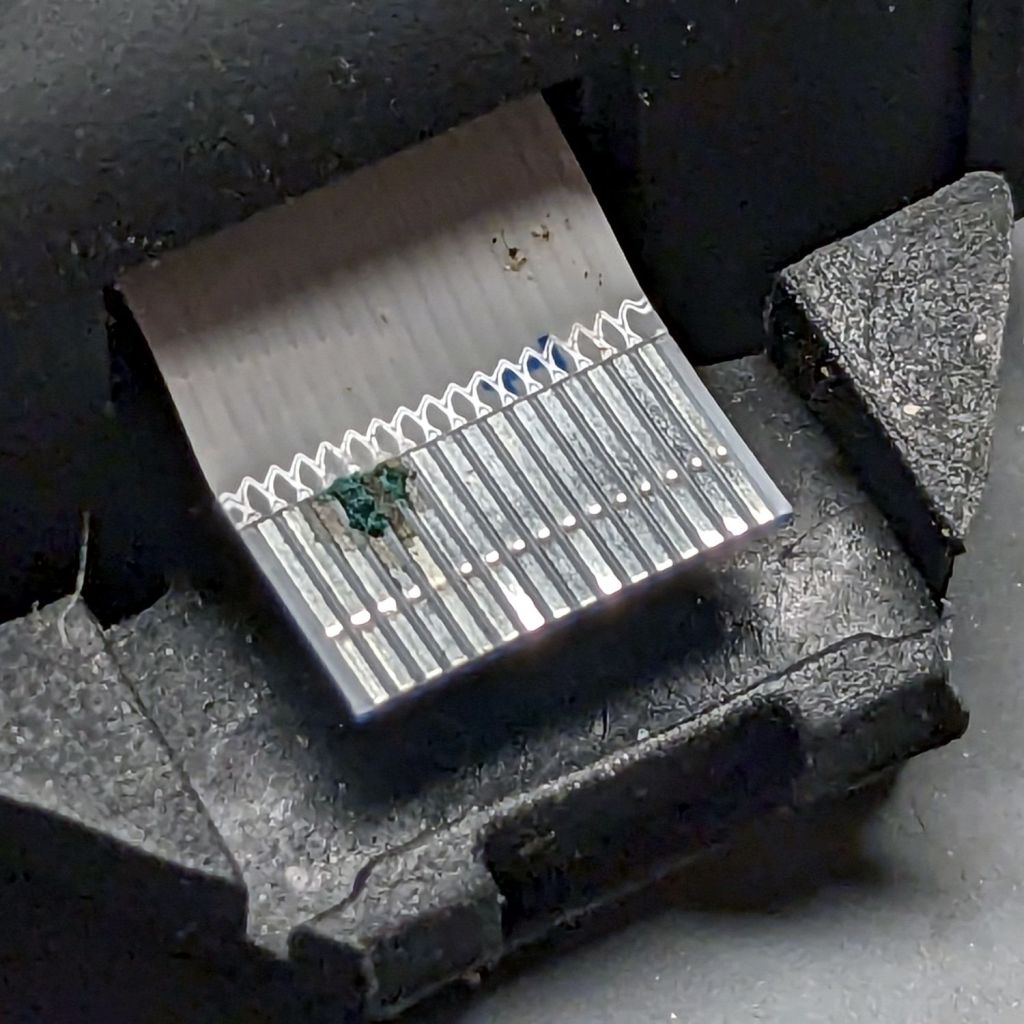
Come to find out my unclean personal habits lodged a particularly corrosive nugget of board chow on the cable:
Moonlander – corroded ribbon cable
It’s a more-or-less standard 0.5 mm pitch cable, but only 20-ish mm long, much shorter than the cables carried by the usual sources. ZSA sells them for $2 each, plus $25 courier shipping, so I bought three; they arrived in two days from halfway around the planet.
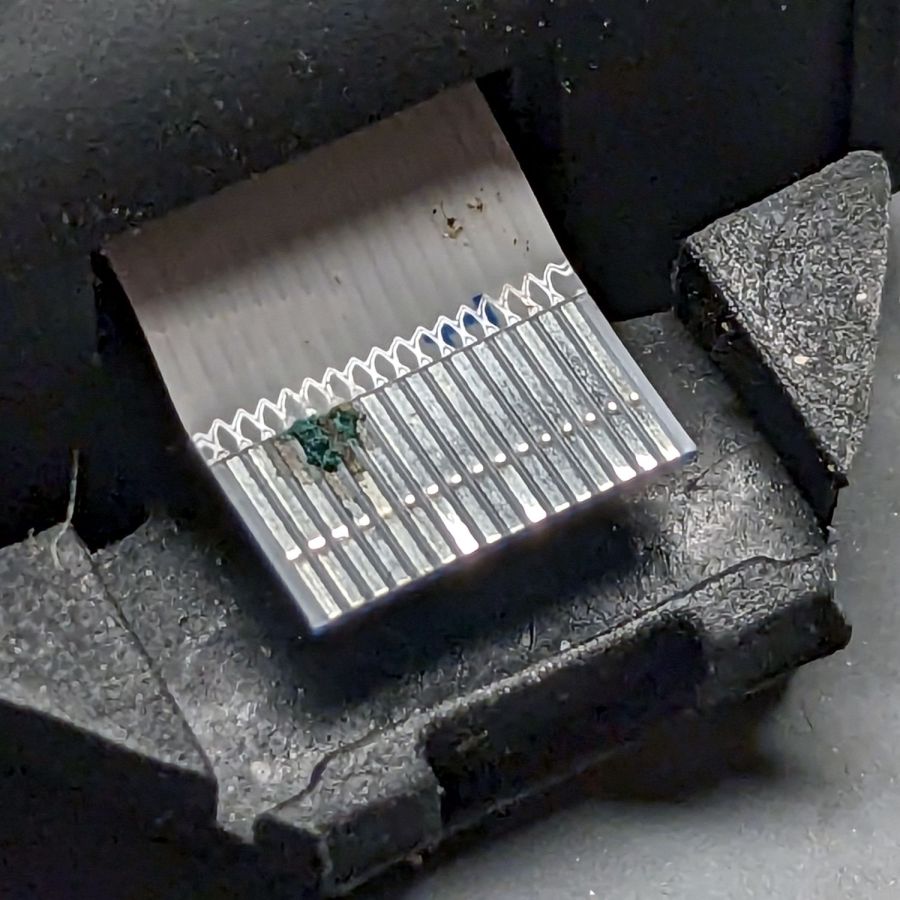
Because I don’t foresee my personal habits changing any time soon, I tucked a Kapton tape snippet in the gap to serve as a gutter:
Moonlander thumb cluster – tape shield installation
That’s with the two hinge screws out and the cluster eased down-and-away from the keyboard enough to get the tape pressed against the keyboard.
With the screws installed and the cluster at its normal most-downward angle, the gutter closes up:
Moonlander thumb cluster – tape shield folded
With the cluster in its normal operating position (for me, anyway), the gutter is nearly invisible:
Moonlander thumb cluster – normal position
For the record, I tucked the remaining ribbon cables inside the left-hand thumb cluster against future need.
While pondering what to do with the shattered kitchen scale, I got a bottom-dollar replacement touting its rechargeable lithium battery. After giving it the obligatory charge-before-using, I put it in service. Five days later, its battery was dead flat discharged.
So I gutted it to extract the battery:
Cheap digital scale – lithium cell
It’s a cute little thing, isn’t it?
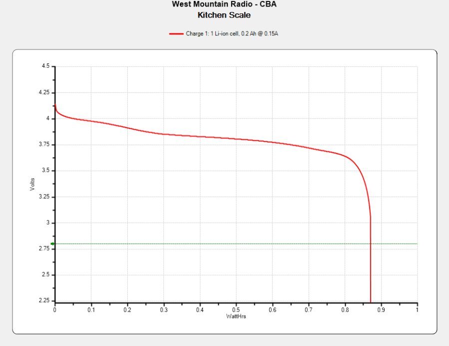
Much to my surprise, the obligatory battery rundown test showed it matches its 0.74 W·hr label:
Kitchen Scale – Charge1
We all know where this is going, right?
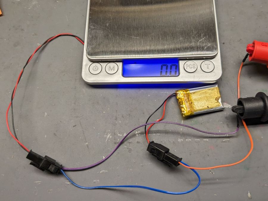
Crunche a connector on the battery, another on the scale, and make up a suitable current tap for a meter:
Cheap digital scale – current measurement setup
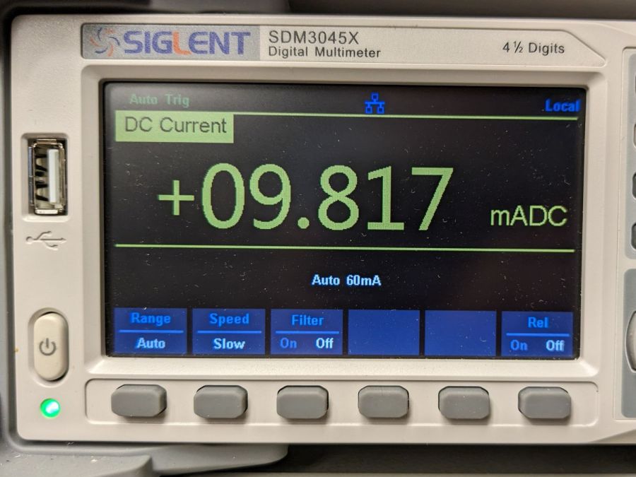
Which looked like this:
Cheap digital scale – active current
That’s about what I found for the craptastic scale running from a pair of CR2032 primary cells, so it’s not out of line.
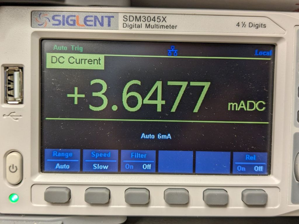
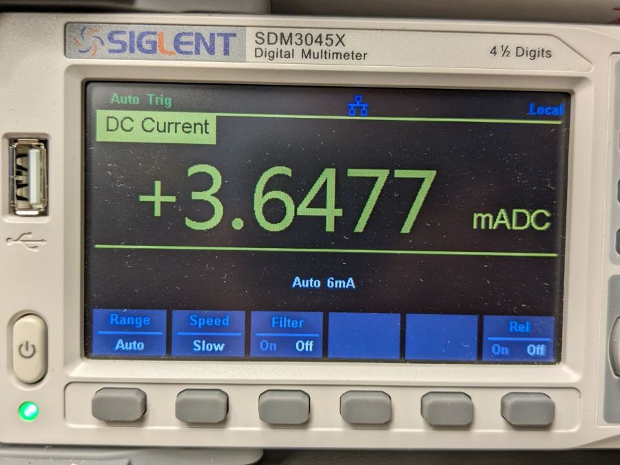
Turn off the scale and measure the idle current:
Cheap digital scale – inactive current
Do you think I got a dud?
For all I know, the little microcontroller under the epoxy blob is running a continuous attack on my WiFi network, with the intent of siphoning off all my sensitive bits. Ya never know.
Dividing the battery’s 200 mA·hr rating by 4 mA says it really should be dead in 50 hours, which is close enough to five days: diagnosis confirmed!
Rather than fight, I switched to a battery with more capacity:
Cheap digital scale – NP-BX1 replacement
It’s long past its prime, but ought to last for a month, which is about as long as the shattered scale survived on a similar battery.
After a year’s service in my Sony AS-30V helmet camera, the Newmowa NP-BX1 lithium cells perform pretty nearly as well as they started out:
NP-BX1 – Newmowa 2022 – 2023-08
Recharging the cells after that test averaged 907 mA·hr within 2%, so they’re still reasonably well grouped.
The camera burns 1.9 W, so the worst of the cells has a 100 minute runtime = 3.3 W·hr/1.9 W × 60 min/hr,.
Our usual weekday rides run a little over an hour and I change the batteries during our longer weekend rides, so they rarely see more than an hour’s use.
A recent 1-¼ hour = 75 minute ride soaked up 687 mA·hr, just about exactly 75% of 907 mA·hr. Gotta love it when the numbers work.
Surprisingly good performance, given the drama involved in finding those cells. I wonder if that will hold next year when I buy another set?
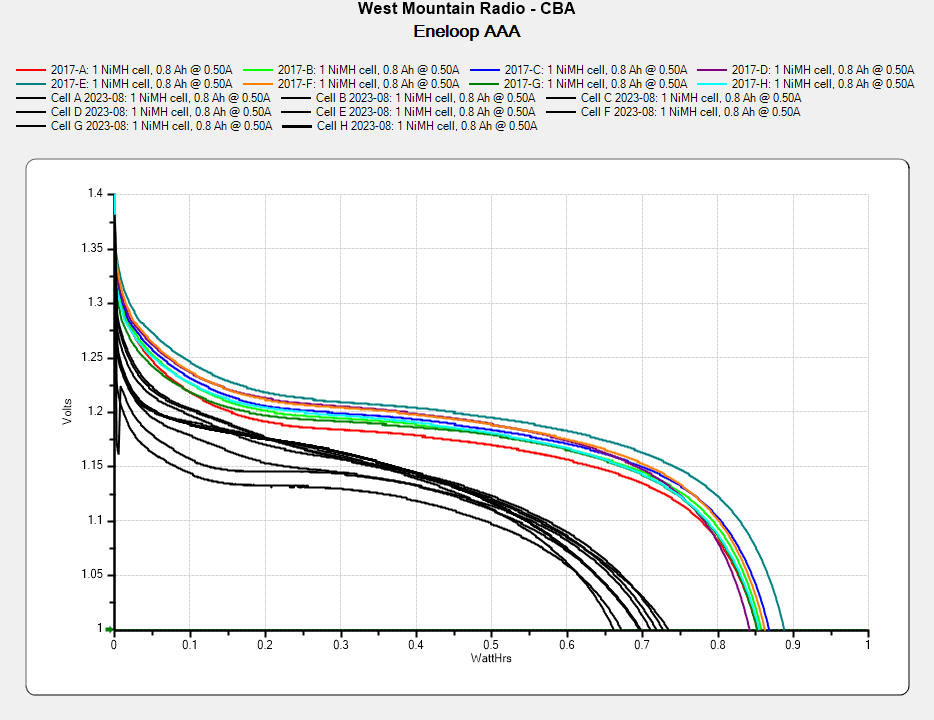
For the last six years, a set of eight Panasonic Eneloop AAA cells have been marching in pairs through the Superflashes in lockstep alphabetic order. We ride several times a week, less in the winter, and I changed the batteries once a week whether they need it or not, so they’ve gone through maybe 200 charge cycles. With four pairs and two bikes, that’s 100 cycles each.
They’re not dead yet, but they’re showing signs of age:
Eneloop AAA – final – 2023-08
In round numbers, the capacity is down 20% from their original 850 mW·hr. The 50 to 75 mV depression is probably more significant for an LED power supply intended for alkaline cells, as the light was running from 2.3 V instead of 3 V.
They worked surprisingly well, all things considered.