When I rewired the guts of the digital tattoo power supply to eliminate the series foot switch, I kept the original wiring polarity, with the black wire to the sleeve and the red wire to the tip:

It’s the same color code I (strongly) recommend in the Squidwrench Electronics Workshops: use any color for the ground / common wire as long as it’s black, then, if you have a red wire, use it for the positive supply. You can use yellow for the higher supply voltage, but stop being clever.
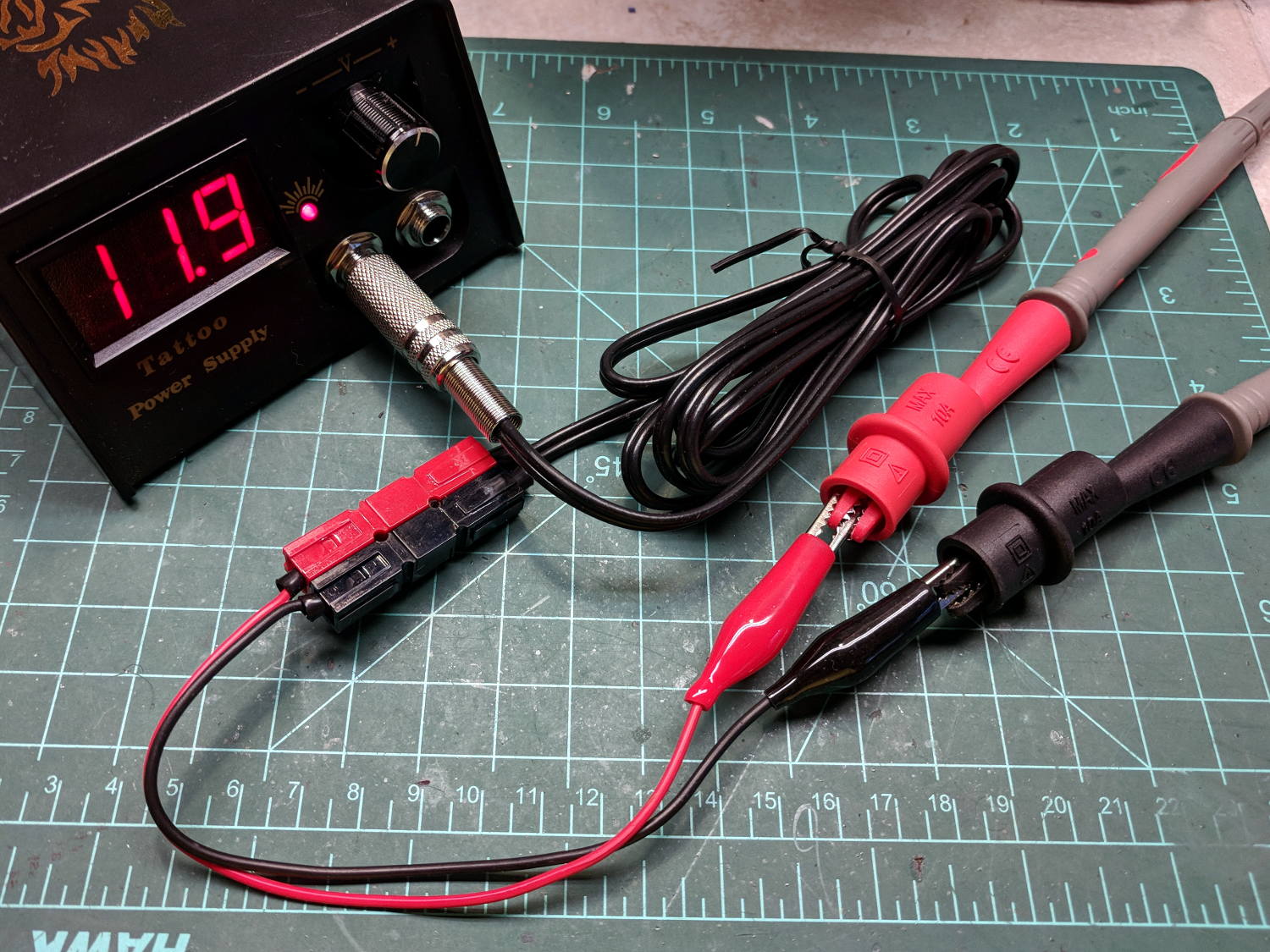
I put suitably colored Powerpoles on the far end of the cable to replace the standard tattoo machine spring clip connector, so I can attach clip leads, battery test fixtures, and so forth and so on.
We wired the supply into a clip-leaded diode measurement setup with a current limiting resistor and a pair of multimeters to measure the diode current and forward voltage, whereupon we noticed all the meters displayed negative voltages and currents.
After a frenzy of wire-checking verified their setup was all good, I forced the simplest possible test, herein recreated on my bench:
Which produced this display:
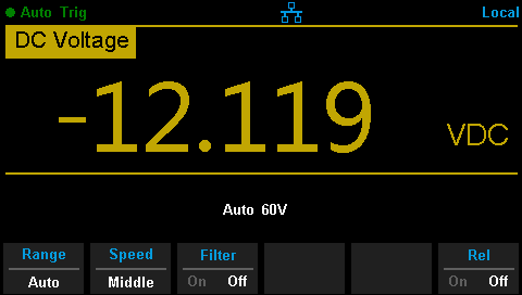
Huh.
After a brief exploration of “Trust, but verify” territory, we swapped the clip leads from the power supply and continued the mission.
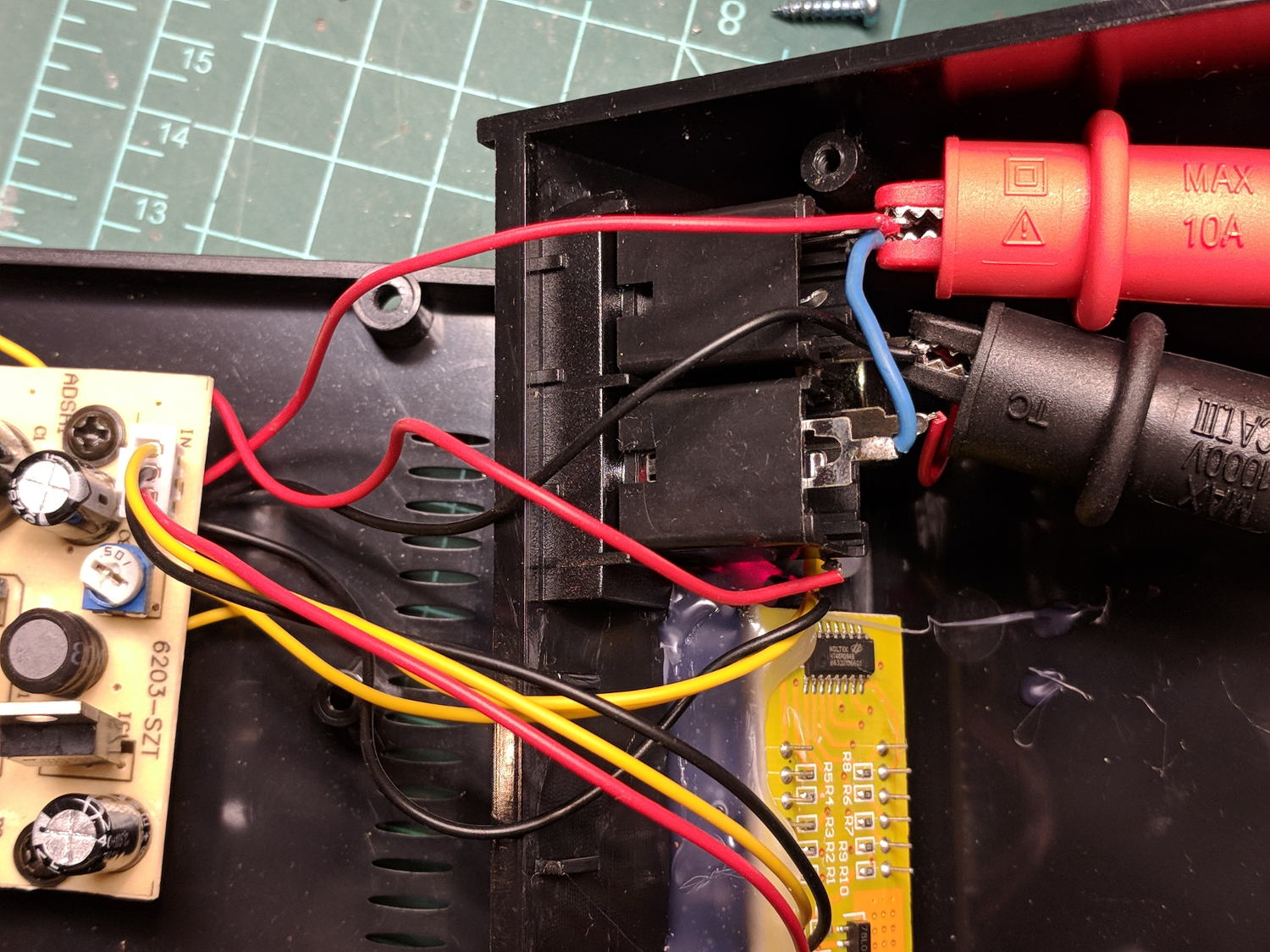
Back on my bench, I pulled the supply apart and measured the voltage at the jack terminals:
Still negative. Huh.
The bottom of the power supply PCB shows exactly what you should expect by now:
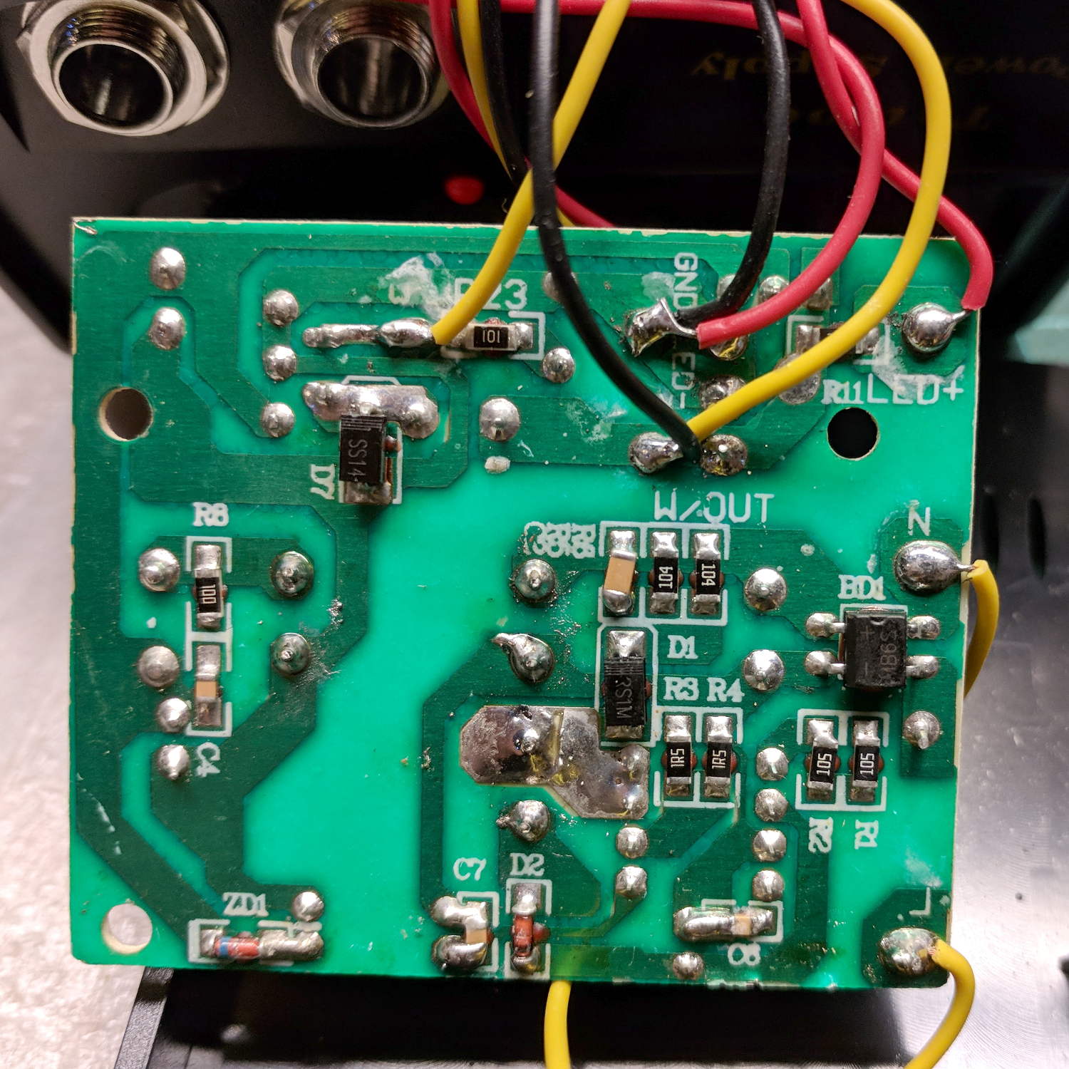
The red wire near the top of the board is, indeed, soldered to the trace labeled GND and goes to the jack’s tip terminal; the adjacent black wire goes to the front-panel LED. Similarly, the black wire just below it, soldered to the same trace as the yellow wire, goes to the jack’s sleeve terminal; that trace also connects to a resistor leading to the trace labeled LED+ and the LED’s red wire.
Although tattoo machines run from DC supplies, their motors or vibrators don’t depend on any particular polarity and will run fine with a backwards supply.
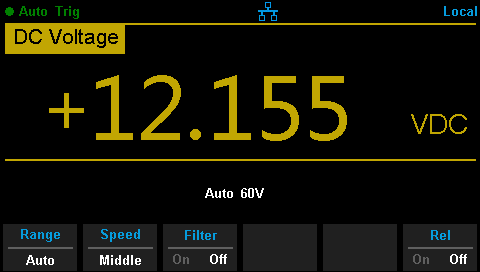
Resoldering the red and black wires where they should go produces the expected sign at the jack:
Although measuring and plotting diode voltages and currents may seem tedious, actually wiring stuff together and taking data reveals how difficult the real world can be.
I trusted the supply’s internal color code and, although I’m certain I tested the Powerpoles, I obviously didn’t notice the meter’s sign.
Memo to self: Sheesh.