Ed Nisley's Blog: Shop notes, electronics, firmware, machinery, 3D printing, laser cuttery, and curiosities. Contents: 100% human thinking, 0% AI slop.
Having just finished tweaking the nosepieces on my new sunglasses into shape, it’s worth mentioning a few pliers you should have.
This set of pliers (PN HH02075SET) from Circuit Specialists is absolutely invaluable. Mine were about twice the current price; the picture looks the same.
You’ll use these four metal-forming pliers (PN 60398) from Micro-Mark somewhat less often, but when you need ’em (like for adjusting your glasses), you need ’em bad. Mine were about half the current price, but I’m sure they cost the same in constant dollars.
I picked up a bunch of surplus Plato 170 flush cutters a long time ago, but even their current price isn’t too forbidding. Great for circuit board work.
Most of the time you need just a single PWM output, but when you’re driving a transformer (or some such) and need twice the primary voltage, you can use a pair of PWM outputs in push-pull mode to get twice the output voltage.
A single PWM output varies between 0 and +5 V (well, Vcc: adjust as needed), so the peak-to-peak value is 5 V. Drive a transformer from two out-of-phase PWM outputs, such that one is high while the other is low, and the transformer sees a voltage of 5 V one way and 5 V the other, for a net 10 V peak-to-peak excursion.
A 50% duty cycle will keep DC out of the primary winding, but a blocking capacitor is always a good idea with software-controlled hardware. A primary winding with one PWM output stuck high and the other stuck low is a short circuit that won’t do your output drivers or power supply any good at all.
An Arduino (ATMega168 and relatives) can do this without any additional circuitry if you meddle with the default PWM firmware setup. You must use a related pair of PWM outputs that share an internal timer; I used PWM 9 and 10.
The timer tick rate depends on what you’re trying accomplish. I needed something between 10 & 50 kHz, so I set the prescaler to 1 to get decent resolution: 62.5 ns.
// Times in microseconds, converted to timer ticks
//  ticks depend on 16 MHz clock, so ticks = 62.5 ns
//  prescaler can divide that, but we're running fast enough to not need it

#define TIMER1_PRESCALE   1     // clock prescaler value
#define TCCR1B_CS20       0x01  // CS2:0 bits = prescaler selection
Phase-Frequency Correct mode (WGM1 = 8) runs at half-speed (it counts both up and down in each cycle), so the number of ticks is half what you’d expect. You could use Fast PWM mode or anything else, as long as you get the counts right; see page 133 of the Fine Manual.
The phase of the PWM outputs comes from the Compare Output Mode register settings. Normally the output pin goes high when the PWM count resets to zero and goes low when it passes the duty cycle setting, but you can flip that around. The key bits are COM1A and COM1B in TCCR1A, as documented on page 131.
As always, it’s easiest to let the Arduino firmware do its usual setup, then mercilessly bash the timer configuration registers…
// Configure Timer 1 for Freq-Phase Correct PWM
//   Timer 1 + output on OC1A, chip pin 15, Arduino PWM9
//   Timer 1 - output on OC1B, chip pin 16, Arduino PWM10

 analogWrite(PIN_PRI_A,128);    // let Arduino setup do its thing
 analogWrite(PIN_PRI_B,128);

 TCCR1B = 0x00;                 // stop Timer1 clock for register updates

// Clear OC1A on match, P-F Corr PWM Mode: lower WGM1x = 00
 TCCR1A = 0x80 | 0x00;

// If push-pull drive, set OC1B on match
#if PUSH_PULL
 TCCR1A |= 0x30;
#endif

 ICR1 = PERIOD_TICKS;           // PWM period
 OCR1A = PERIOD_TICKS / 2;      // ON duration = drive pulse width = 50% duty cycle
 OCR1B = PERIOD_TICKS / 2;      //  ditto - use separate load due to temp buffer reg
 TCNT1 = OCR1A - 1;             // force immediate OCR1x compare on next tick

// upper WGM1x = 10, Clock Sel = prescaler, start Timer 1 running
 TCCR1B = 0x10 | TCCR1B_CS20;
And now you’ll see PWM9 and PWM10 running in opposition!
Memo to Self: remember that “true” does not equal “TRUE” in the Arduino realm.
My simple collet pusher has been working OK, but the locking pin was a few mils too small for the hole in the spindle and eventually put a burr on the edge. The fix is straightforward, although I’ve been putting it off for far too long; I warned you about this in the original post.
The locking hole in the spindle starts life at 0.094 inch. I grabbed a #40 drill in a pin vise and drilled it out to 0.098 by hand, which wasn’t nearly as difficult as you’d think, took out all the deformed metal, and didn’t even leave any burrs. Ditto for the hole in the collet pusher.
My heap yielded a defunct #40 drill, from which I cut 15 mm of shank with a Dremel abrasive wheel. Chucked the shank stub in the drill press, spun it up, and applied a Dremel grindstone to put a very short taper and a nice smooth end on it.
Pulled the old pin from the handle I built a while ago, added a dot of urethane glue to the new pin, and squished them together (tapered end out!) in a vise until cured. Done!
If you’re building an Arduino shield, you must align the connectors & holes with the Arduino board underneath. That seems to be easy enough, assuming you start with the Eagle CAD layout found there, but when you’re starting with your own layout, then things get messy.
Here’s how to verify that you have everything in the right spot, at least for Diecimilla-class boards. Start by holding the Arduino board with the component side facing you, USB connector on the upper left. Rotate your own PCB layout appropriately or stand on your head / shoulders as needed.
With the exception of J3, the center points of the connectors & holes seem to be on a hard 25-mil grid with the origin at the lower-left corner of the board (below the coaxial power jack):
J3 (AREF) @ (1.290,2.000)
J1 (RX) @ (2.150,2.000)
POWER @ (1.550,0.100)
J2 (AIN) @ (2.250,0.100)
Upper-left hole = 0.125 dia @ (0.600,2.000)
Upper-right hole = 0.087 dia @ (2.600,1.400)
Lower-right hole = 0.125 dia @ (2.600,0.300)
Reset button = (2.175,1.065)
Offsets between points of interest:
connector rows Y = 1.900
right holes Y = 1.100
UL hole to UR hole = (2.000,-0.600)
UL hole to J3 X = 0.690
J3 to J1 X = 0.860
J3 to POWER X = 0.260
POWER to J2 X = 0.700
J1 to UR hole = (0.450,-0.600)
J2 to LR hole = (0.350,200)
Note that the three etched fiducial targets are not on the 25-mil grid. They’re not on a hard metric grid, either, so I don’t know quite what’s going on. Fortunately, they’re not holes, so it doesn’t matter.
Memo to self: perhaps I’ve measured & calculated & transcribed those values correctly. Double-check before drilling, perhaps by superimposing double-size PCB layouts on a light table or window. Finding it then is much less annoying than after drilling the board… ask me how I know.
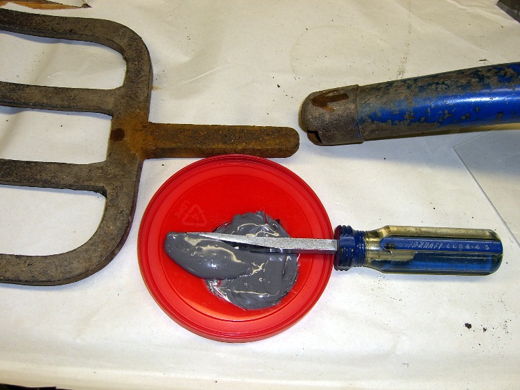
Mary intercepted a complete, albeit defunct, garden fork on its way to the trash and brought it home for repair. It turns out that the handle’s socket had loosened and split around the tine shank, but all the pieces were pretty much in place.
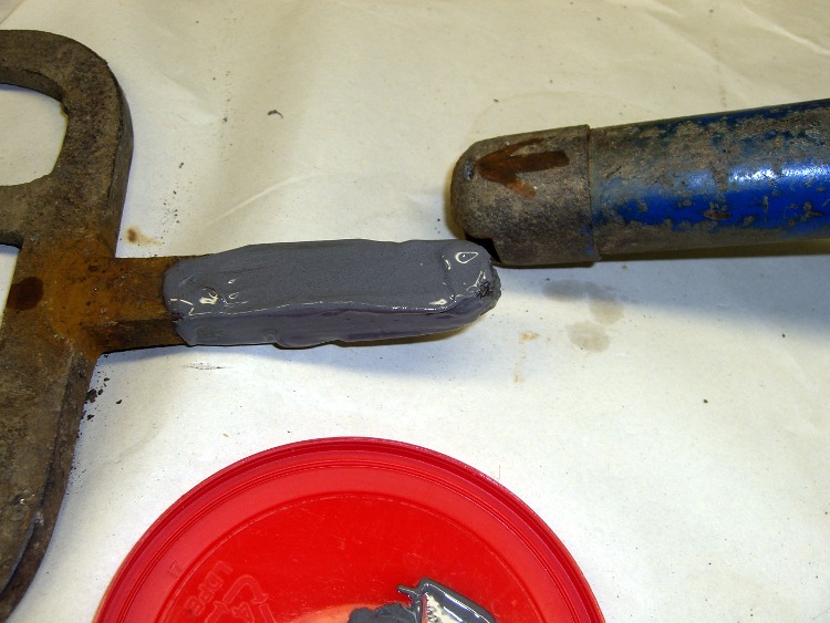
Mix the epoxy with my dedicated mixing screwdriver, butter up the shank, blob the excess epoxy into the socket, shove the parts together, clean off the outside globs, and let it cure overnight.
The trick is to get enough epoxy in the socket to fill the voids and mechanically lock the shank in place. This probably won’t work for forks used by burly guys who heave rocks over the horizon, but for our simple needs it’ll do just fine.
Pitchfork repair – epoxy mix
Pitchfork repair – buttering up the shank
Every now and again it’s OK to do an easy repair without a trace of CNC…
Maybe that stogie wasn’t lit, but I’m exceedingly glad I wasn’t close enough to be sure!
You may need to click on the picture to get the joke; I was high up on a gravel bank, but probably still within the blast zone.
My pocket camera was set to mandatory flash from whatever I’d been doing the last time I used it. The piddly little xenon tube even lit up the retroreflective tape on the semitrailer about 200 feet away across the highway.
Mary was giving one of her vegetable gardening presentations and had the projector go into Mute mode all by itself. It’s hard to debug something like that under pressure, but (as nearly as we can tell) the projector’s remote control (!) got squashed inside the tote bag and managed to tell the projector to go mute itself…
The remote control has buttons that stand proud of the surface by about 2 mm and, worse, they’re exposed from all sides. There seems to be no way to turn the mumble thing off, other than by removing the batteries, so I conjured up a quick-and-dirty button shield. Not the fanciest thing I’ve ever made, but it’s sufficient for the purpose.
[Update: Apologies to all you Arduino fans who think this should have something to do with a remote-control circuit board plugged atop a Diecimila, but I think the Arduino designers could have picked a more descriptive term than “shield”. Plenty of folks seem to arrive here by searching for the obvious keywords and go away unhappy. If you’re looking for Arduino stuff, click on the obvious tag in the right-side column that’ll call up everything I’ve written about on the subject… ]
Sizing the perimeter
I thought about making a tidy form-fitting slab that would fill the entire space between the button matrix and the case, but that gets into curved edges and fussy fitting; fortunately, I came to my senses. Without wanting to make a prototype to get the second one right, I simply trimmed the outside of the polycarbonate slab to a ruthlessly rectangular 33×50 mm. That gives about 2 mm clearance on each side of the button matrix and fits with about 1 mm clearance from the case. The lengthwise dimension is what it is.
The 29×46 mm pocket must be about 3 mm deep to clear the button tops.
The G-Code came from the Hugomatic pocketRect2points generator, which worked just fine; normally I hammer out my own G-Code, but I was leaving on a trip the next day. The cut depth of 1 mm per pass was probably too conservative. A cutting speed of 300 mm/min with a 2000 rpm spindle worked reasonably well with water cooling.
Pocket milling with water coolant
A 1/8″ end mill produced corner radii that matched the buttons fairly well, which means it took a loooong time to chew out the pocket. The picture shows the mill knee-deep in a pool of water and swarf; I vacuumed the chips out at the end of each pass and added more water.
Double-stick tape held the polycarb & sacrificial plate to the tooling plate, which worked surprisingly well given that I just wiped the grunge off and squashed it down. A machinist’s square aligned the rectangle closely enough and, of course, I used the laser aligner to set the coordinate zero to the left-front corner.
For lack of anything smarter, a rubber band holds the shield in place on the remote. I thought about fancy hinges and Velcro and stuff like that, but the projector is used by non-technical folks and, as nearly as I can tell, the remote control never gets used at all.
Quick and dirty, indeed: about two hours, first doodle to snapping the rubber band, including a bit of time wasted on an ancient G-Code generator that spat out bad coordinates.