Ed Nisley's Blog: Shop notes, electronics, firmware, machinery, 3D printing, laser cuttery, and curiosities. Contents: 100% human thinking, 0% AI slop.
Raccoon in treeI met this fellow on my way out of a recent MHV LUG meeting; he was up a tree between the library parking lot and the adjacent (and rather busy) gas station / convenience store, minding his own business while performing body maintenance.
That’s pretty much in the midst of the City of Poughkeepsie, but raccoons have figured out that the livin’ is easy around people. I’m sure he’s also figured out dumpster diving, although he’s likely not looking for discarded electronics…
For some reason, everybody thinks LEDs put out nice Gaussian beams. Unless the specs say so, it just ain’t so. Some pix from the Trinity Robotics Contest show the situation.
This is the table used in the RobotWaiter contest. It has a visible red LED on each face to aid in locating and aligning, but you better not depend on the actual beam intensity as a function of angle!
The same picture in pure IR shows the situation with a bit more contrast. Although it’s a visible red LED and I have a visible-cut filter on the lens, there’s enough energy for an image.
So I bought 530 bucks worth of new tires for the van; it’s ten years old with 66k on the clock. Picked the most suitable ones:
Near the top of the Consumer Reports list
Best constellation of features for our use
Available at the local tire shop
CR is essentially the only place that does actual across-the-board tests; you can disagree with their methodology, but it’s pretty much the only game in town.
I wound up at the local tire shop after bouncing off one of the online sources. In this case, tire + shipping + installation costs more online; the local shop was one of the online source’s installers.
So I went direct. They’re aboveboard: the balance + installation charge is the same no matter where the tires come from.
Had a 10:00 appointment and it took 90 minutes to get out of the shop. Not impressed.
The tire pressure monitor light came on halfway home. Well, OK, maybe it’s noticed the tires are bigger? But it’s a differential rotation counter, sooo… that’s not the problem.
Checked the pressure after letting the tires cool off for a few hours.
37 – Left rear
32 – Right rear
40 – Left front
34 – Right front
The pressure monitor was definitely doing its job!
Adjusted them all to 36 psi (hard, but we’ll see how it rides), reset the monitor, and it’s all good.
Factory trained and certified mechanics, my obscene-gerund deleted-noun.
Oh, and the lug nuts were evidently tightened by Andre the Giant… gotta break those suckers free before we do much more driving!
Given the overall slovenliness of the recently kludged tool length probe switch on my Sherline CNC mill, you have to have to ask yourself… does that thing actually work?
This boils down to a simple test: repeatedly poke the switch and record the Z-axis trip point. If it’s the same every time, then the switch is repeatable and life is good. If not, then the switch is moving: not good.
One good measurement being worth a thousand expert opinions, I devoted some Quality Shop Time to measuring the switch. The picture shows the simpleminded setup.
There’s a broken carbide cutter (I have a disturbing number of these) held in a collet, with its blunt end downward. The spindle isn’t turning, for obvious reasons.
The probe switch is as far in the -X direction as I can conveniently put it, screwed down to one of the T-nuts holding the tooling plate in place. The G30.1 tool change position is a few inches directly above the switch position.
The dial test indicator grabbed in the vise has 0.5 mil graduations, so it’s eyeballable to more-or-less 0.1 mil, although I have my doubts about the mechanical repeatability in that range. The arm is horizontal, with the XYZ origin set to the top of the ball.
The G-Code (shown below) probes the switch to establish & display the tool’s reference length. Actually, what we’re displaying is the Z-axis coordinate where the switch trips, then computing the new tool length from those values.
Then it does these steps 10 times:
Go XY=0.0 Z=5, just above the indicator ball
Go to Z=0.0. The indicator should read 0.0, too.
Prompt me to write down the indicator reading
G30 to the tool change location
Probe the (unchanged) tool & display the new Z-axis value
So I did that and here’s the result. The second column is the indicator reading in mils, with negative numbers being further down toward the tooling plate. The third column is the Z-axis coordinate of the probe switch trip in mm.
Iteration
Z @ Origin (mils)
Tool Z @ Probe (mm)
0
0.0
-50.008042
1
0.0
-50.008873
2
0.0
-50.010536
3
0.0
-50.012032
4
-0.1
-50.013526
5
0.0
-50.014193
6
-0.2
-50.014857
7
-0.1
-50.016686
8
-0.1
-50.016852
9
-0.1
-50.017185
10
-0.1
-50.018514
Probe drift
-0.010472
Now, that just cries out for a graph, doesn’t it?
Probe Switch Repeatability
The slope of the regression line says the switch is tripping about one wavelength of infrared light (1 micron) further down at each probe. Well, now, that’s not too bad, is it?
After ten probes, it’s descended about 10 microns, call it 0.3 mils, which is somewhat more than what the dial test indicator reports: 0.1 mil or just slightly more than the width of the indicator’s needle away from the 0.0 line.
It turns out that the switch doesn’t have any mechanical overtravel whatsoever, so when the switch contacts close, the button is already pretty much bottomed out.
Switch ReleasedSwitch Over-pushed
The left picture shows the tool a few millimeters over the switch. Notice that the top of the black plastic switch body is snug against the metal frame. Although you can’t see it here, there’s nothing but air below the body; the brown hot-melt glue secures the sides and submerges the terminals & wiring.
The right pictures shows the situation after probing the switch at 300 mm/min. The switch body is pushed slightly downward from the metal shell, showing that the Z axis drive didn’t screech to an instant halt after the switch tripped.
My back of the envelope said it’d stop in about 7 mils from 12 in/min (call it 0.2 mm from 300 mm/min, which is what I actually used here). Turns out it’s more like 15 mils, about 0.4 mm. So much for the back of the envelope…
On the other hand, what’s a binary order of magnitude among friends?
The routines below do an initial probe at 300 mm/min, back off about 1 mm, then probe again at 10 mm/min. The theory was that the switch overtravel would soak up the initial probe and the second, more gentle, probe would always trip at the same Z-axis level.
Another good theory all shot to hell…
I should do the initial probe at, say, 100 mm/min and (to speed things up) put the tool change location as close to the switch as the longest tool will allow. That should cut the overtravel down to 5 mils, which ought not be a real problem.
However, I think the switch is usable as-is. It’s certainly more accurate than my manual tool height adjustment and I really don’t do many jobs that require more than a few tool changes, separated by long periods of chewing away at the part.
I suspect the switch gradually oozes back to its original position after being rudely poked, but I ought to check that, too.
The G-Code to make the tests happen:
(Tool length probing test)

(--------------------)
( Initialize first tool length at probe switch)
( assumes metric units!)

O<Probe_Init> SUB

G49					( clear tool length compensation)
G30					( to probe switch)
G91					( relative mode for probing)

G38.2 Z-90 F300		( trip switch on the way down)

G0 Z1				( back off the switch)
G38.2 Z-10 F10		( trip switch slowly)

#<_ToolRefZ> = #5063	( save trip point)

G90					( absolute mode)
G30					( return to safe level)

O<Probe_Init> ENDSUB

(--------------------)
( Initialize new tool length at probe switch)
( assumes metric units!)

O<Probe_Tool> SUB

G49					( clear tool length compensation)
G30					( to probe switch)
G91					( relative mode for probing)

G38.2 Z-90 F300		( trip switch on the way down)

G0 Z1				( back off the switch)
G38.2 Z-10 F10		( trip switch slowly)

#<_ToolZ> = #5063				( save new tool length)

G43.1 K[#<_ToolZ> - #<_ToolRefZ>]	( set new length)

G90					( absolute mode)
G30					( return to safe level)

O<Probe_Tool> ENDSUB

(--------------------)
( Set up first tool)

G21					( metric units)

(msg,Verify origin at indicator ball, hit Resume)
M0
(msg,Verify G30.1 above tool change switch, hit Resume)
M0
(msg,Verify blunt tool installed, hit Resume)
M0

O<Probe_Init> CALL

(debug,Initial tool length = #<_ToolRefZ>)

O100 REPEAT [10]

G0 X0 Y0
G0 Z0
(msg,Record indicator Z-axis reading, hit Resume)
M0

G0 Z5				(get air)
G30					(to tool change position)

O<Probe_Tool> CALL
(debug,Tool length offset = #<_ToolZ>)

O100 ENDREPEAT

M2
And here you thought that switch was a total piece of crap, didn’t you?
We stopped in Alfred NY to try out some trikes at The Bicycle Man, went to The Terra Cotta (not that one) for lunch, and parked on a side street. Every parking meter along the street (free on Saturday, fortunately) had an array of house flies parked along the upper edge.
Perhaps this is the best place for flies to warm up before a flight? Was there a recent hatching?
They swarmed off the meters as we passed, then settled back in the same way.
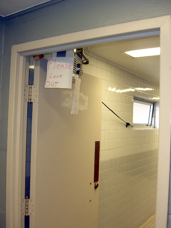
Found this installation in the Mens Room at the first rest area inside New York on westbound I-90. The extension cord trails out the window and around to the back of the building…
I suppose the building’s heaters had failed, but, still, this seems odd.
I’ve seen all manner of exceedingly fancy and painstakingly constructed tool length switch stations, but it seems ordinary snap-action / tactile-feedback switches are repeatable enough for most purposes. I selected a switch from my stash with these qualifications:
physically small — fits on Sherline table
plastic button — avoid nicking the cutters
many more in the stash — not a special-order item
cheap – ’nuff said
A few snippets of heat stink shrink tubing later…
Switch detail
After puzzling over the mounting, I snagged a chunk of aluminum U-channel from the heap, poked a 10-32 clearance hole in one end, and held the switch in place while slobbering brown hot-melt glue over it. The glue is rigid when cool, so the switch isn’t going anywhere, but it’s mounted with some air space below to allow crushing when the probe routine screws up.
The button stands slightly proud of the U-channel, so even wide tools have side clearance. If the tool doesn’t stop when the switch trips (it could happen!), the entire switch will bend downward until the Z-axis drive stalls as the tool crushes the rubble or snags on the side of the U-channel.
At which point I just cut the cable, hammer the hot-melt glue and switch rubble out of the U-channel, solder up another switch, blob it in place, and continue the mission… from scratch, though, because the stored tool height reference value will be kaput.
The U-channel can be screwed down to a T-nut, clamped directly to the table, or affixed wherever it’s needed. If the Sherline had home switches, it’d be better to mount the probe switch in a fixed location somewhere, then use a fixture offset for the part, but I’m not there yet.
The switch doesn’t have much overtravel: when the contacts activate with a tactile click, the button is pretty much bottomed out. However, unless you’re driving the tool into the switch at a dead run, it ought to stop moving fairly quickly.
Back of the envelope: I have the Z axis acceleration set to (a sluggish) 3.0 in/s/s. Approaching the switch at 12 in/min = 0.2 in/s , it’ll screech to a halt in 67 ms = (0.2 in/s)/(3.0 in/s/s). Assuming the average velocity while stopping is 0.1 in/s, the distance works out to 7 mils, which shouldn’t pose a problem.
Then drive up off the switch enough to clear the backlash and drive down at nose-pickin’ speed, so the axis stops pretty much instantly when the switch clicks.
Some not-very-exhaustive testing suggests the repeatability for a single tool is well within 0.03 mm, about 0.001 inch, which is entirely satisfactory for my purposes.
[Update: It’s pretty good, all things considered. A simple experiment is there.]
The overall procedure:
Laser align XY to the part origin, home X&Y axes
Execute G49 to clear any existing tool length compensation
Insert first tool, align to Z=0 on part, home Z axis
Eyeball align XY to the switch with the tool just above
Jog Z comfortably high, execute G30.1 to set tool change location
Fire up your program!
The program probes the first tool length and saves that as the reference length. Each subsequent tool change gets probed and the tool offset becomes the difference between the new length and the reference length.
The initial probing routine:
O<Probe_Init> SUB

G49					( clear tool length compensation)
G30					( to probe switch)
G91					( relative mode for probing)

G38.2 Z-90 F300		( trip switch on the way down)
G0 Z1				( back off the switch)
G38.2 Z-10 F10		( trip switch slowly)

#<_ToolRefZ> = #5063	( save trip point)

G90					( absolute mode)
G30					( return to safe level)

O<Probe_Init> ENDSUB
Note that the G30 coordinates are stored in native units, which are inches for my Sherline mill. To get to that Z height (for safety, before moving) while using metric units:
G0 Z[#5183 * 25.4]
The G38.2 coordinates are stored in whatever units the G20/G21 mode calls for, so they can be applied directly to tool length compensation. That seems odd, as EMC assumes the tool table uses native units.
There does not seem to be any way to determine which unit mode is active, although the probe speed depends on that setting. although I suppose I could set a global variable to the desired probe speed and leave it up to the G-Code program(mer) to get it right. Yeah, like that’ll work…
Anyhow, each subsequent tool gets probed thusly:
O<Probe_Tool> SUB

G49					( clear tool length compensation)
G30					( to probe switch)
G91					( relative mode for probing)

G38.2 Z-90 F300		( trip switch on the way down)
G0 Z1				( back off the switch)
G38.2 Z-10 F10		( trip switch slowly)

#<_ToolZ> = #5063				( save new tool length)

G43.1 K[#<_ToolZ> - #<_ToolRefZ>]	( set new length)

G90					( absolute mode)
G30					( return to safe level)

O<Probe_Tool> ENDSUB
With those two routines in hand, this demo code shows how it’s done…
G21					( metric units)

(msg,Verify origin at proper location, hit Resume)
M0
(msg,Verify G30.1 at tool change switch, hit Resume)
M0
(msg,Verify first tool installed, hit Resume)
M0

O<Probe_Init> CALL

G0 X0 Y0 Z0
(msg,Verify return to origin, hit Resume)
M0

M6 T2
O<Probe_Tool> CALL

G0 X0 Y0 Z0
(msg,Verify return to origin, hit Resume)
M0

M6 T3
O<Probe_Tool> CALL

G0 X0 Y0 Z0
(msg,Verify return to origin, hit Resume)
M0

M6 T4
O<Probe_Tool> CALL

G0 X0 Y0 Z0
(msg,Verify return to origin...)
M2
The M6 Tx commands make use of a
TOOL_CHANGE_AT_G30 = 1
line in Sherline.ini, which tells the Axis automagic manual tool changer routine to traverse to the G30 position and pop up a prompt to (manually) change the tool. When you click OK, the subsequent CALL command invokes the tool length probe routine and away it goes.
This whole lashup doesn’t have a lot of power-on hours, but I really like how it works!
A tip o’ the cycling helmet to the folks behind EMC2…