Ed Nisley's Blog: Shop notes, electronics, firmware, machinery, 3D printing, laser cuttery, and curiosities. Contents: 100% human thinking, 0% AI slop.
Using pretty much the same setup as before, I put the Thermal Switch Block at the top of the MK5 Thermal Riser Tube and the little heatsink at the bottom. The heatsink sat between the bolt head and left just enough room that I could snake the thermocouple bead into the brass tube, so these temperatures should be much more representative of the actual Thermal Riser.
After getting everything stuck together, I discovered that I’d interchanged the thermocouple leads. Rather than fixing that, take note that the T1 and T2 datasets represent different objects, but the same physical position: T1 on the bottom, T2 on the top.
I skipped the staged warmup, cried “Fire the Thing-O-Matic!” and ran it to 225 °C while recording temperatures every 5 minutes along the way. The graph looks like this:
Thermal Riser Tube Temperature Graph – block on top
They’re not quite exponentials, because the Core temperature gets flattened at the top, but they’re still pretty.
The top-to-bottom temperature differential has increased to 35 °C, although the top temperature still hits 90 °C. I think there are countervailing forces at work:
The thermocouple is in better contact with the Heatsink: the bottom of the tube really is hotter with the Heatsink at that end.
The Thermal Block gives a better measure of the top-of-Tube temperature, because that thermocouple is intimately connected to the Block. The Tube top is about the same temperature, but the previous Heatsink temperatures were lower.
In short, I trust these readings a bit more than the previous ones.
But, as before, the Switch Block is still too hot for a 100 °C Thermal Switch. The next step is to add a somewhat larger heatsink from my Parts Heap and see what happens.
The general idea: measure the Thermal Riser Tube temperatures, so as to figure out where to put the Thermal Cutout Switch that will kill the Thing-O-Matic if the cartridge heater drive circuitry gets stuck on. Ideally, there will be a location suitable for the 100 °C NC switch I have on hand, but you’d use the same technique to make sure any switch would work.
So, to begin.
With the Thermal Switch Block just over the bolt heads and the small heatsink just under the acrylic sheet at the top, a pair of thermocouples attached to my old Fluke 52 meter reported temperatures.
The top thermocouple (T2 data) touches, ever so gently, the small heatsink, so it’s reporting mostly heatsink temperature and bit of the surrounding air. It moved slightly after the first measurement, despite the masking tape visible in the upper right corner of the picture.
The bottom thermocouple (T1 data) is tucked into the small hole in the Switch Block, so it’s reporting the real block temperature that the Thermal Switch will eventually experience.
A third thermocouple is taped in the corner of the Z axis stage against the acrylic arch, directly beside a cartridge heater inside the insulation wrap. During these proceedings that temperature rose from 25 °C ambient (due, most likely, to hand warmth while positioning all this stuff) to about 35 °C.
And, of course, the standard thermocouple on the MK5 Core reports the actual temperature inside the insulation wrap.
I raised the MK5 temperature in 50 °C steps, then 25 °C to 225 °C, waiting until the Block temperature more-or-less stabilized, while recording temperatures every 5 minutes. On this time scale, the Thermal Core temperature stabilized over the course of a single measurement.
With at that in mind, the results look like this:
Thermal Riser Tube Temperature Graph – block on bottom
At normal extruding temperatures above 200 °C, the red trace shows the Switch Block running about 15°C above green Heatsink trace and topping out at 91 °C. The top of the Riser Tube is somewhat cooler with that big Block hanging on the bottom, too: 70 to 74 °C, rather than the 83 °C I measured there.
The Block temperature increases by 7 °C when the Core increases by 25 °C, obviously depending on a bunch of nonlinear effects. A rash extrapolation suggests a 100 °C switch would trip before the Core hit 275 °C.
However, that Block gets uncomfortably close to 100 °C, which is the point where the Thermal Switch will go click and kill the whole show. I’d rather have a bit more headroom to allow for warm summer weather and a heated build chamber.
So the next experiment puts the Thermal Switch Block at the top of the Thermal Riser Tube…
The best place to mount a thermal switch (or a thermal sensor, depending on how much you trust your circuitry) is on the MK5 Thermal Core, but that’s far too hot for the switches I have in hand. As a compromise, I decided to mount the switch on the Thermal Riser tube leading vertically upward to the Filament Drive gear: good thermal contact, a solid mount, and out of harm’s way.
All the alternative locations seem worse. Tucking it inside the insulation wrap doesn’t provide a solid mechanical mount, so you don’t get a repeatable position and the leads get bent every time you move something. Bolting it to the plate over the Core looks solid, but that’s just a flat sheet of metal with four screws connecting it to the Core: no real thermal contact surrounded by lots of cooling air.
One good omen: with an operating temperature well under 100 °C, JB Industro Weld epoxy will work fine and eliminate any need for fussy clamps and fittings.
So I sawed off a random chunk of aluminum plate, squared it up in the Sherline mill, and poked a few holes in it. This doodle has dimensions roughly equivalent to the final object, but absolutely nothing is critical other than the 5/16 inch central hole:
Switch block sketch
The 4-40 setscrew secures the block to the Thermal Riser. Aluminum expands considerably more than stainless steel, so I dropped a snippet of PTFE wire insulation into the hole as a rubberdraulic plunger.
The lug on the top provides strain relief for the wires; it’s not an electrical connection. The modular phone cable trailing off to the Thermal Cutout box has wires insulated with low-temperature plastic, so a few inches of Teflon hookup wire keep them out of the Danger Zone.
The small hole is just big enough for a thermocouple bead.
This is what the thing eventually looked like, but I made some measurements before sticking that switch in place:
Just fixed a flat on my bike which, like that one, came from the tire liner chewing through the tube. The holes are above the raised 28″ molded into the tube, at the upper-left corner of the tire liner impression.
Schwalbe tube with tire liner abrasion
In this case, the tire liner (which, judging from the color, was a Slime) was too short by maybe 50 mm. This view inside the tire shows a 10 mm gap where the ends didn’t overlap as they should:
Schwalbe Maration tire with liner abrasion
I don’t trim the rear-tire liners, but comparing a handful in the drawer shows that the as-sold lengths differ by a few tens of millimeters. The Marathons are husky tires, but the tread OD isn’t all that much different from stock tires: that’s the definition of a 700-series tire.
That we’re getting repeated flats from tire liners intended to eliminate flats is, mmmm, disturbing. Looking at the condition of the tire treads, however, shows we’re not getting an order of magnitude more flats from road debris, so it’s a net win. I doubt we could get through a month of riding without a flat; I replace tires when the carcasses accumulate enough gashes that the tire liners begin extruding through the tread.
Also, remember that these samples come from three bikes that travel upwards of 2000 miles a year (each!), not just one bike ridden along a nice rail trail on weekends…
Over the past few weeks I’ve printed the gears and plate from TheRuttmeister’s Coloso-Gear MK5 extruder Thing and flatted the shaft on a moderately husky (but not hyperthyroid) NEMA 17 stepper motor. While tearing the Thing-O-Matic down to add thermal switches to the Extruder Head, I converted the MK5 Filament Drive into a stepper extruder. Much to my astonishment, when I plugged the cable in and fired up ReplicatorG … It Just Worked!
Even more amazing: the first pinout arrangement turned the motor in the correct direction!
Coloso-Gear Stepper Extruder
Some nasty pincushion distortion makes the larger gear look misaligned, but it’s parallel to the mounting plate and correctly engaged with the drive gear.
The motors arrived with short stubs of thin yellow wire on the IDC motor connectors, which I soldered directly to a much longer cable. The Parts Heap disgorged a chubby 8-conductor signal cable; I used pairs of wires for each motor connection, although one conductor would have entirely enough copper. The two cable ties around the motor prevent flexing those delicate wires as the Z stage moves.
Two tweaks to the MK6 Stepstruder profile in thingomatic.xml produced the right answers:
Set motor_steps = 1456
Set stepspermm = 48.2
Running the motor at 2.0 rpm for 30 sec should produce exactly 1 revolution of the big gear. I marked and counted the teeth on the larger gear as it rotated, and came up with 56 teeth. It’s a 51 tooth gear, so reducing the default 1600 steps/rev by 51/56 produces 1457. A defunct MBI stepper driver board that now only does full steps provides power; I resoldered all the chip pins and the fault isn’t due to external causes like no-lead solder.
Then run it for 60 seconds at 2.0 rpm and it’s under by maybe 1/10 of the tooth-to-tooth spacing. Adjust 1457 x 101.9/102 = 1456. Run it for another minute and it’s spot on.
I measured 60.45 mm for two revolutions of the big gear, so it’s 30.23 for one rev, which requires the aforementioned 1456 steps. Averaging more revolutions would yield more digits, but given the rubbery nature of molten filament, three significant figures seems entirely sufficient. I suspect this depends greatly on how deeply the extruder drive embosses the filament, so it’ll require some fine tuning.
Back of the envelope for the DC extruder at 255 PWM: feed = 45 mm/s, 0.35 mm thickness, w/t = 1.7 = 0.56 mm width gives 6.9 mm3/s. The filament is about 2.9 mm dia = 6.6 mm3, so it passed through the extruder at a bit over 1 mm/sec. There’s some windage involved in all those numbers and the extruding rate obviously depends on the temperature.
The stepper (from the usual eBay seller) is a Minebea 17PM-K150, which doesn’t appear in their catalog listing, so it’s likely one of their many custom motors. The stack length resembles the 17PM-K3xx series, which means roughly 1 A rated current. Setting the driver current to 500 mA (VREF = 1 V) produces enough torque that I cannot pull the filament back hard enough to stop it.
The step rate at 2 rpm is:
48.6 step/s = (2 rev/min) x (51/7) x (1 min/60 s) x (200 step/rev)
At that lethargic pace, the K3xx motors have something like 0.250-0.300 N·m of torque at rated current. At half current, call it 0.100 N·m and multiply by 51/7 to get 0.700 N·m = 100 oz·in.
The effective drive diameter is 30.23/π = 9.6 mm, so the available force on the filament is 0.7 N·m / 0.01 m = 70 N ≈ 7 kgf = 15 lb. Yeah, but that little 7-tooth gear will snap right off …
The reversal plugin cranks the big gear backwards at 35 rpm, which works out to 850.5 step/s. That ought to work, particularly seeing as how it’s not actually pushing anything.
The NEMA 17 steppers I picked up from eBay as part of the stepper extruder upgrade project have round shafts; that’s not surprising, as they came with pressed-on timing gear pulleys. In their new application they’ll sport plastic herringbone gears and those have setscrews.
Herringbone gears with nut inserts
Both nuts have epoxy potting to prevent moving / rotating under duress. Remember to load the screw threads with beeswax and run it all the way through before you pot the nuts, lest the screw become one with the nut. Yes, the left gear fits a NEMA 23 stepper.
(Those are 14-tooth gears. I’ll actually use a 7-tooth gear, but I printed a bunch of gears to get the hang of it.)
Any time you tighten a setscrew on a motor shaft, it’ll raise a burr on the shaft. You can pull a plastic / printed gear off a ruined shaft because the burr will simply carve a gash through the plastic. A metal-hub gear or pulley will jam solid on the burr; you definitely don’t want that to happen.
The solution, which comes standard on many motor shafts, is a flatted section where the screw can raise a burr without causing a problem. In addition, the flat prevents the screw from sliding around the shaft and producing a circular scar that makes the gear impossible to remove.
Adding a flat requires a few minutes of Quality Shop Time, but will save you considerable hassle later on. Just Do It!
Mummify the motor in masking tape to keep grinding grit and metallic dust out of the shaft bearings, then grab the shaft in a smooth- or soft-jaw vise. I grabbed a machinist’s vise in the bench vise, but use what you have.
Masked motor in vise
Apply a Dremel grinding stone / cutoff wheel along the shaft to produce a flat about the same width as the tip of the screw. The object of the game is to make the flat wide enough to keep the burr on the flat, but not grind half the shaft away.
Don’t grind the shaft without clamping it, because the vibration will destroy the bearings. Clamp the shaft to stabilize it and isolate the motor, then do the grinding.
Flatted shaft with screw
Here’s the shaft after installing & removing the gear. Notice the burr:
Flatted shaft with screw scar
And a detail of the burr:
Flatted shaft scar – detail
It’s not like I’m over-tightening the screw, either: that’s what a hardened screw does to a soft motor shaft.
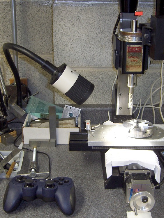
Eks forced me to take a pile of crap useful make-froms, including a gooseneck task lamp that was probably bolted onto a machine tool in its former life. It sported a 20 W halogen bulb, but looked to be just about exactly the right size for those LED floodlights, which is why I didn’t put up much of a fuss about taking it off his hands.
The LED lamps are much bigger than the halogen bulb, but they fit neatly into the housing diameter. All they needed was a bit more front-to-back room, which looked a lot like a chunk of PVC pipe. The housing screws together with a 1.5 mm thread that I can’t produce on my inch lathe; I’m still not set up for thread milling. This being a low-stress application with a lamp that ought to outlast me, I figured I’d just make the belly band slip-fit the two threads, glue it in place, and move on.
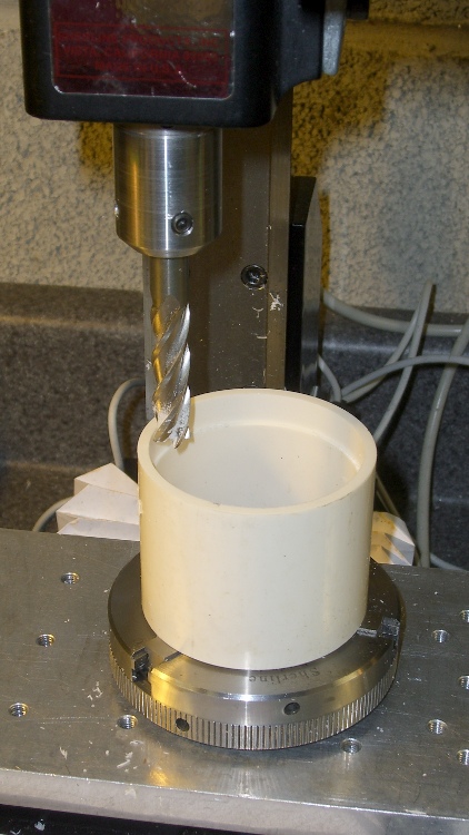
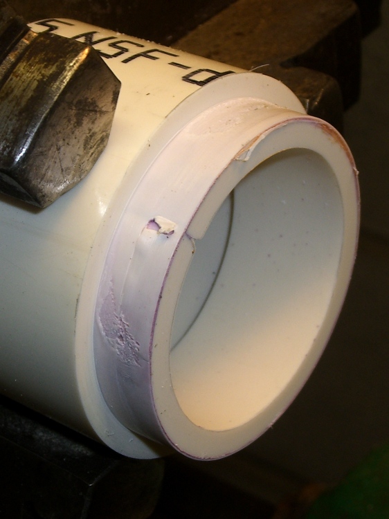
I sawed off a length of PVC pipe, faced off the ends in the lathe, then CNC milled a recess to clear the male threads on the gooseneck part (I hate precision boring in the lathe). Given the rather tenuous grasp of that 3-jaw chuck, I made two passes around the perimeter: pipe ID 52.1, thread OD 54.5, remove 1.2 mm all around, about 9 mm down.
Milling top recess
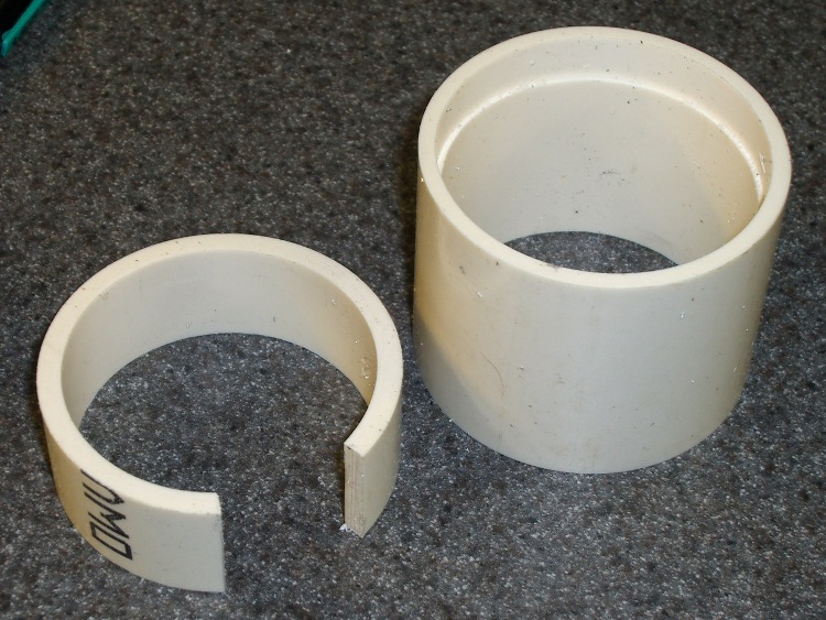
On the other end, the female thread ID = 52.2 and the pipe ID = 52.1, so I glued another ring of PVC pipe inside to provide enough meat to turn it down. Once again, saw off a ring, face the ends, then cut out a segment so that the OD circumference of the inner ring is just slightly smaller than the ID circumference of the outer pipe. The result looked like this:
PVC insert sizing
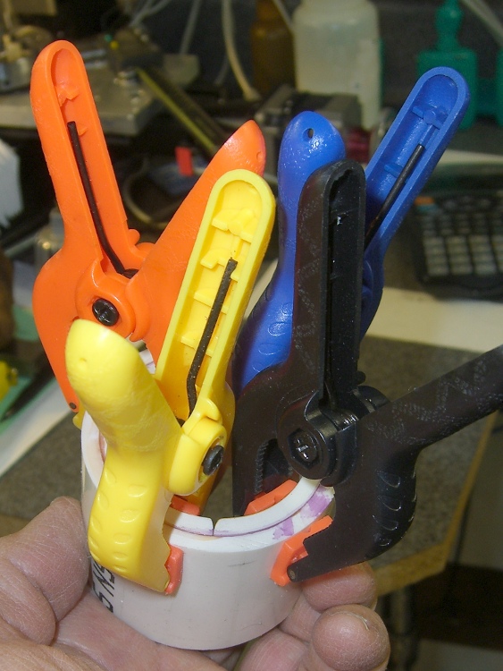
Apply a heat gun to the inner ring until it’s soft enough to stuff into the pipe, clamp it until it hardens, apply PVC cement, and clamp overnight. Contrary to appearances, the ends of the two pipes are flush at the surface. Once again, you cannot have too many clamps:
Clamped PVC insert
Turning down the outside to fit the threads shows just how little meat was left on that pipe:
Skinning down to the insert
While it was chucked up (and despite my dislike of boring) I bored a bevel to accept the LED lamp and adjusted the OD so the lamp fit snugly between the end of the belly band and the lens holder on the front of the housing:
Floodlight in holder
The switch comes from the Parts Heap. A D drill puts a slightly undersized hole that’s just right for the threaded switch; I simply turned it in by hand. A length of zip cord carries the power up the gooseneck, where various ends get soldered to the switch and lamp.
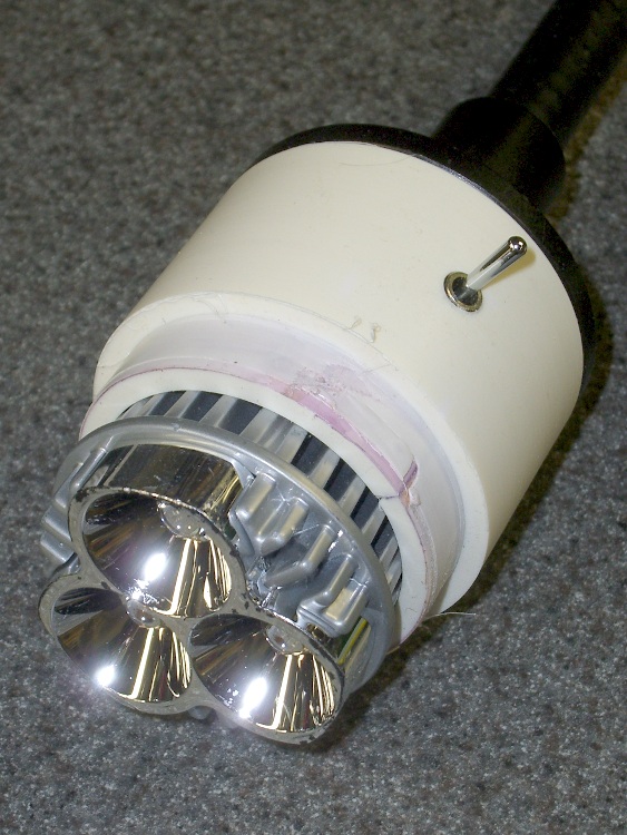
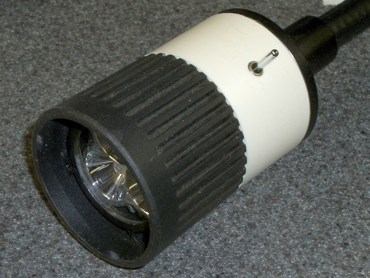
I applied some hot-melt glue to the threads and pushed everything together:
Finished LED Floodlight
The glass lens on the front fits in a molded holder with an annular air gap. The LED lamp housing has all those fancy cooling fins against the inner pipe, so there’s a bit of cooling air flow around the lamp and out through the rear black section. A thermocouple reports the lamp temperature gets up around 75 °C in a 14 °C shop; a 50 °C rise might be a tad warm in the summer, but we’ll see what happens.
The power supply came from the Parts Heap: a 12 V 1 A wall switching power supply in the shape of a wall wart. For now, the zip cord from the lamp terminates in a coaxial power jack that (amazingly enough) fits the wart’s connector, but I’ll eventually put a box in there somewhere.
Clamped the butt end of the gooseneck to the backsplash on the countertop under the mill and It Just Works!