Ed Nisley's Blog: Shop notes, electronics, firmware, machinery, 3D printing, laser cuttery, and curiosities. Contents: 100% human thinking, 0% AI slop.
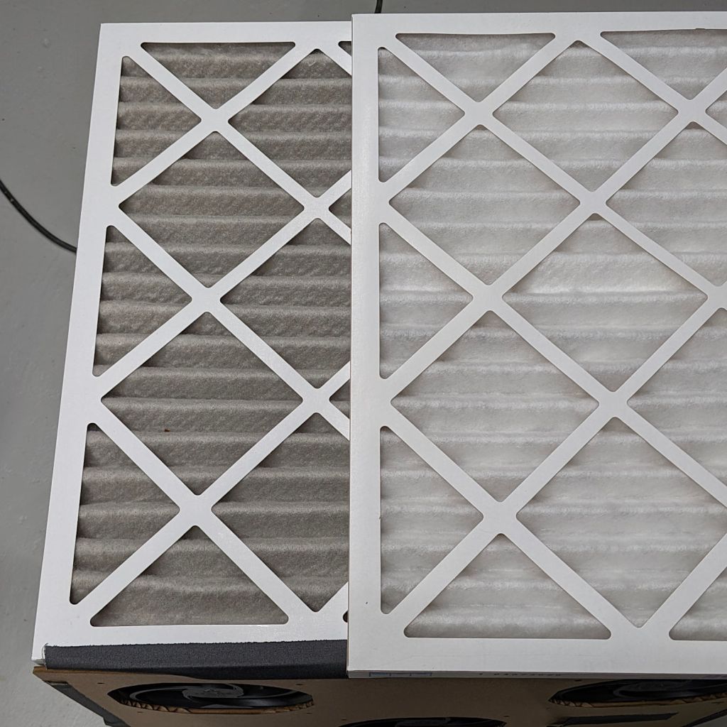
Running continuously for three months made the air filters look like this (with an unused filter on top for comparison):
Basement Air Filter Box – 3 months – A
I have not stretched the image contrast, so the new filter isn’t the pure white in the top picture, but it’s still about the same white as the cardboard frame. The floor is, indeed, painted gray.
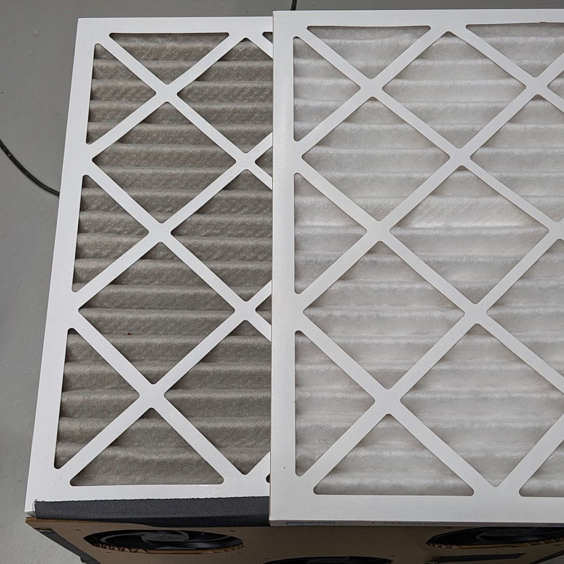
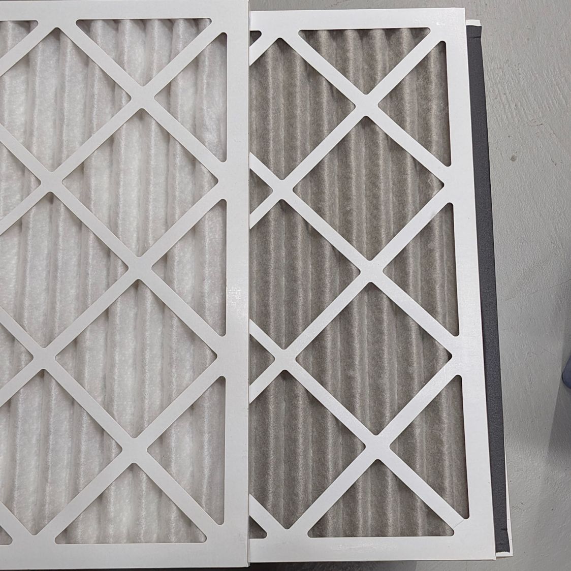
Looking at the pleats in the other direction to show I’m not making it up:
Basement Air Filter Box – 3 months – B
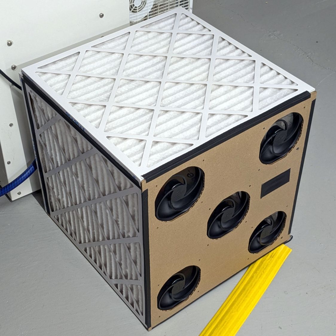
The inside surface of the filters has the same gray appearance. The fans are, unsurprisingly, immaculate.
Totally did not expect that!
The filters sport a MERV 13 rating and snag “most smoke” from the passing air, so they’ve been collecting any fumes not sucked out of the laser cutter, along with whatever arises from other Basement Shop™ activities.
So I’ll buy another set of filters, build another box, and see what accumulates during the next three months.
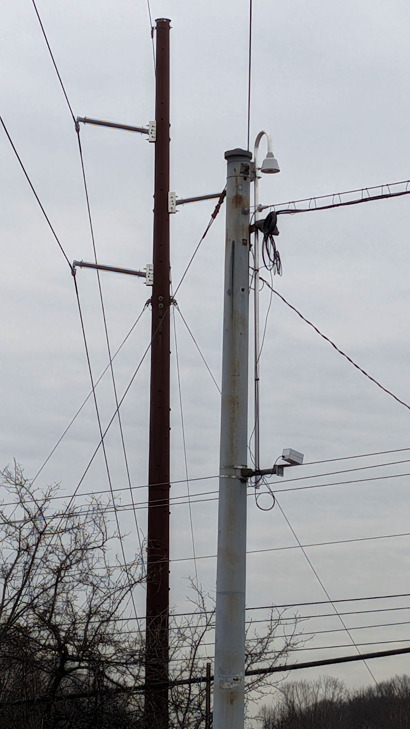
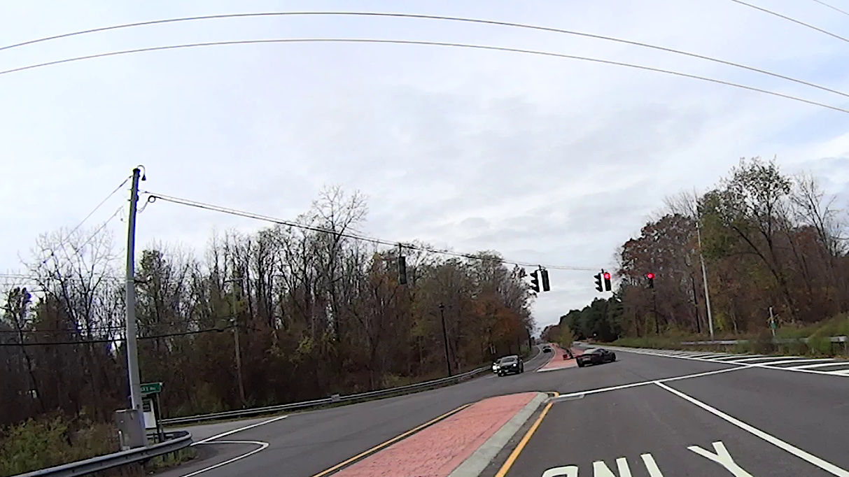
A pair of cameras overlook the intersection of Rt 376 with Zack’s Way from inverted-J mounts (I don’t know the formal name) atop the steel poles supporting the traffic signals:
Traffic Cam – Rt 376 at Zacks Way – north
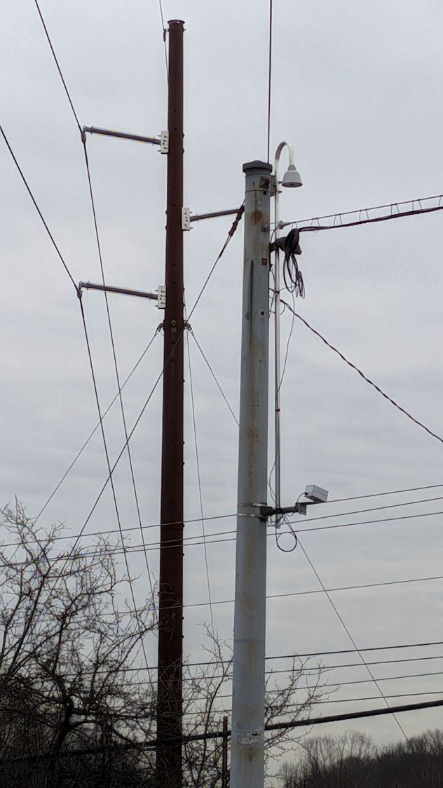
The inverted-J on the south side started equally high, but has been lowered as far as possible, with the camera just below the top of the pole:
Traffic Cam – Rt 376 at Zacks Way – south
My guess: the higher position put the (electrically grounded) mount inside the keep-out zone around the 115 kV power line conductor passing exactly over the pole:
Traffic Cam – Rt 376 at Zacks Way – south – detail
I’m sure lowering the mount came after an interesting discussion, but I’ll never know the rest of the story.
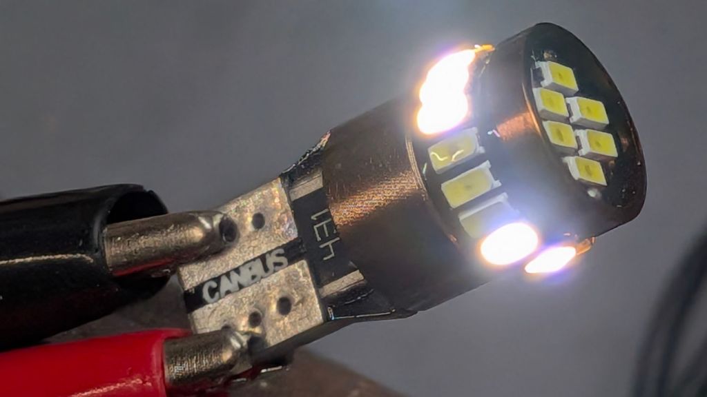
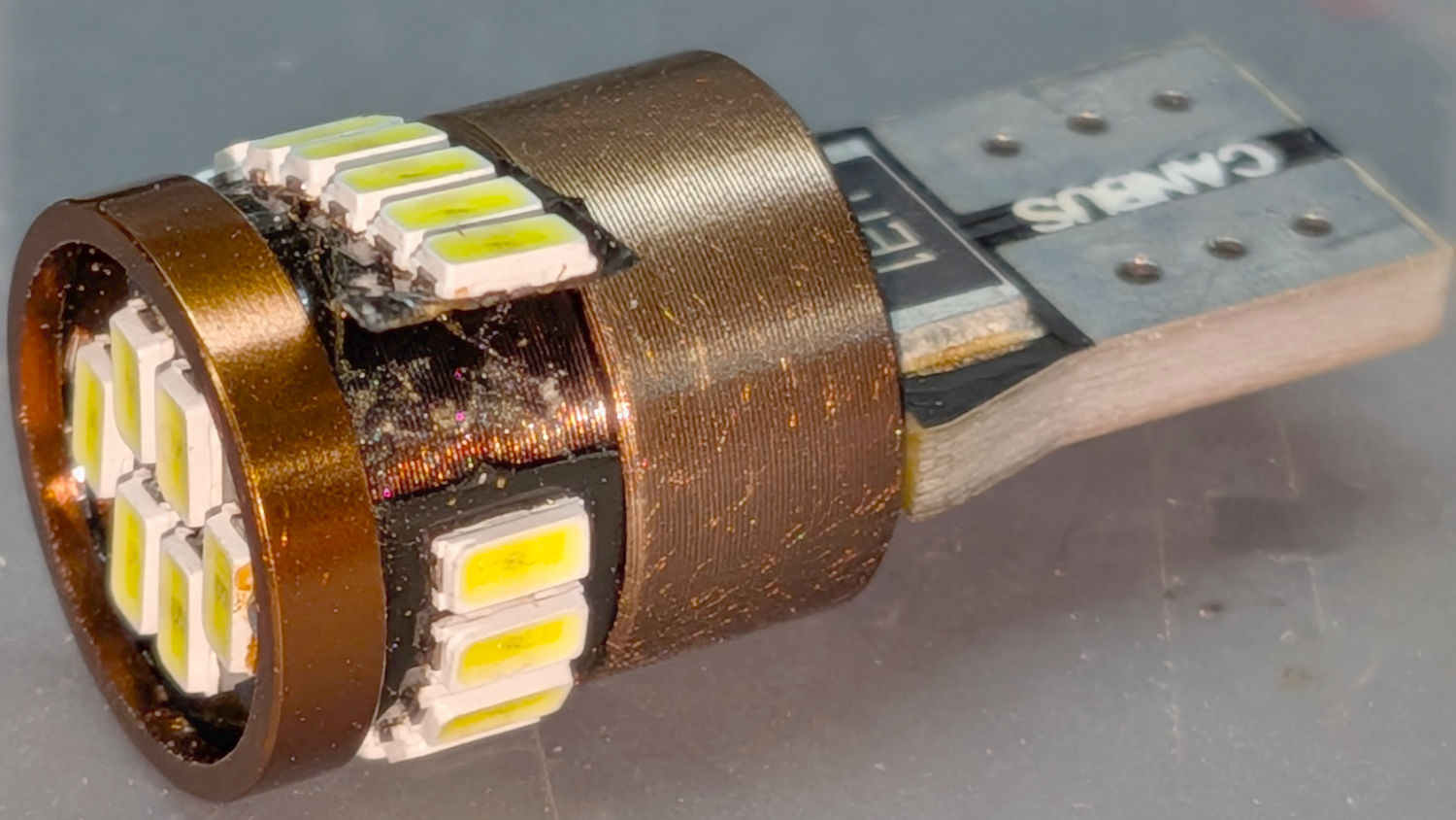
It’s a W5W “parking light” in the same fixture as the melty halogen high-beam bulbs (used as daytime running lights at half power), so it gets toasted on those occasions when we drive somewhere.
The adhesive holding the LED strip to the aluminum shell fossilized and came loose:
White W5W Parking Light – failed adhesive
Now that I know what to look for, I’d get LED bulbs with chips soldered directly to the PCB, although it’s not obvious what holds the PCB to the aluminum frame.
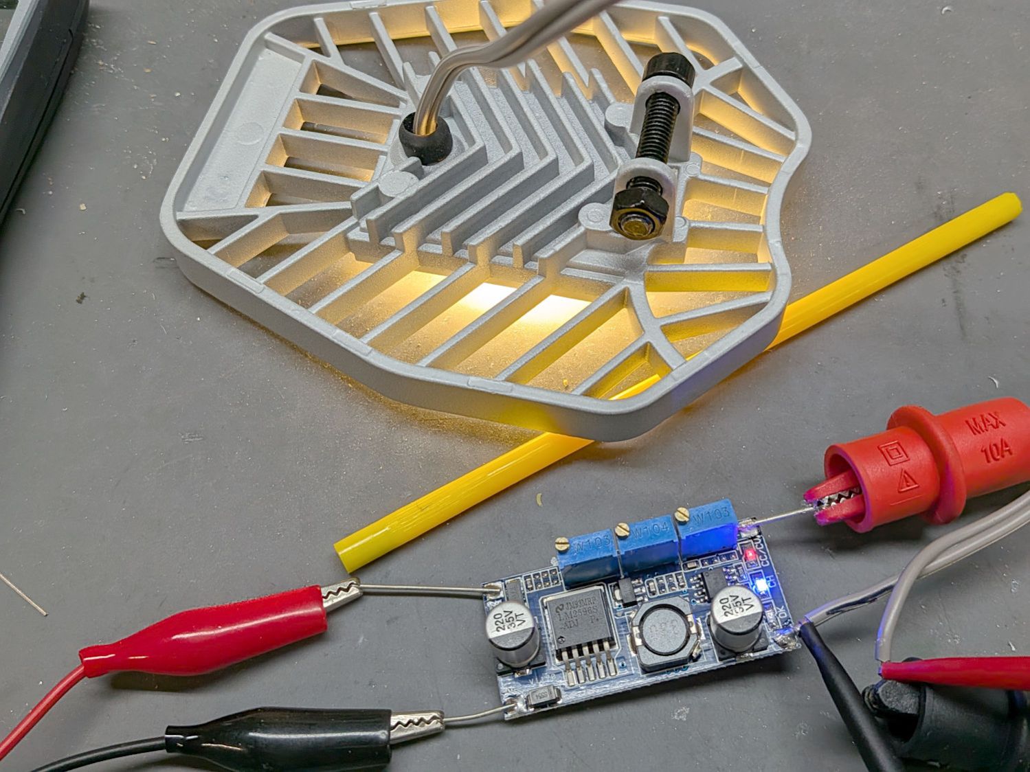
As long as the voltage limit is over about 10 V, it will (likely) never matter, as the LED forward drop doesn’t vary much with temperature. Setting it to something sensible keeps it out of the way.
The middle trimpot apparently sets a voltage for a comparator to light an LED when the battery current drops below that level as it reaches full charge.
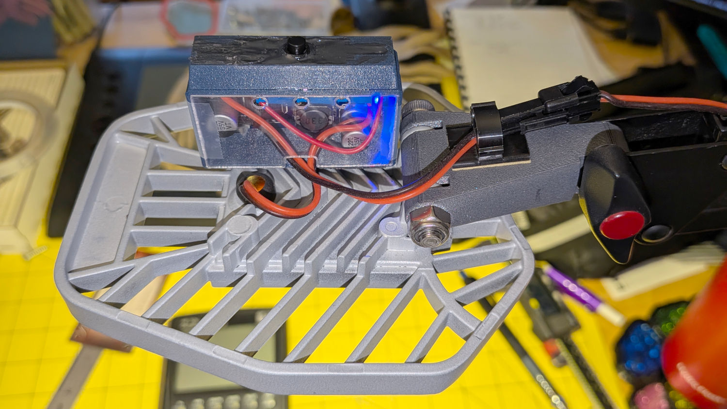
Although the regulator touts its high efficiency, it does run hot and a heatsink seemed in order:
LED Garage Light – heatsink
Stipulated: the fins run the wrong way and it’s sitting in the updraft from the main heatsink. It’s Good Enough™.
The switch on the top comes from the collection of flashlight tailcap switches and controls the 12 V input power. It’s buried up to its button in a generous dollop of JB Kwik epoxy, which seemed the least awful way to get that done.
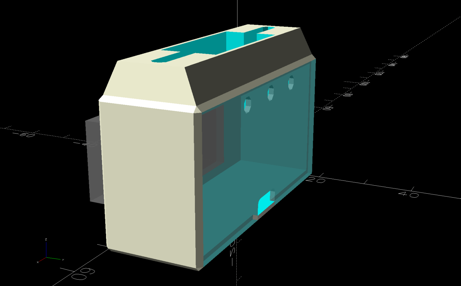
The solid model looks about like you’d expect:
LED Lamp Driver case – switch housing – show solid model
The OpenSCAD code exports the (transparent) lid as an SVG so I can import it into LightBurn and laser-cut some thin acrylic. Two tape snippets hold the lid in place pending more power-on hours, after which I’ll apply a few dots of cyanoacrylate adhesive and call it done.
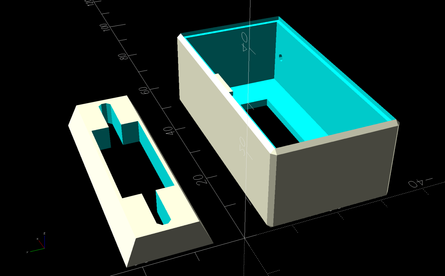
The case builds in two pieces that glue together to avoid absurd support structures:
LED Lamp Driver case – switch housing – build solid model
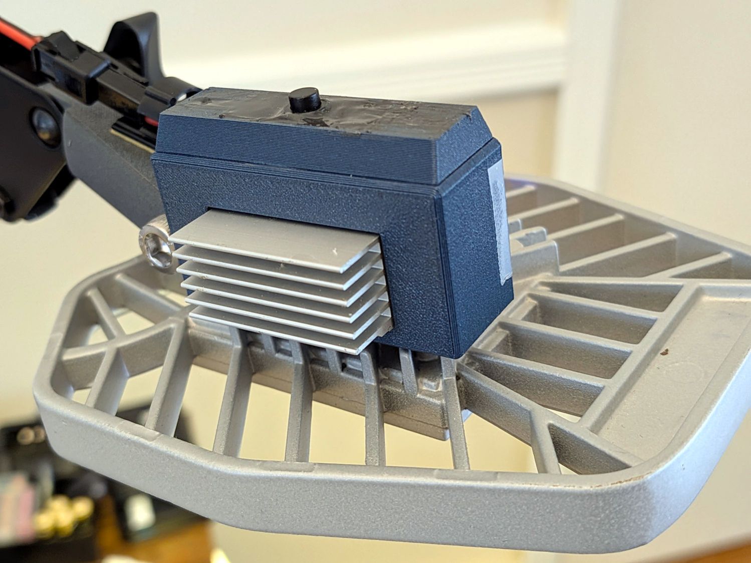
A 3D printed adapter goes between the desk lamp arm and the lamp heatsink bolt:
LED Lamp Driver case – arm adapter – solid model
The OpenSCAD source code files for the case and adapter arm as a GitHub Gist:
This file contains hidden or bidirectional Unicode text that may be interpreted or compiled differently than what appears below. To review, open the file in an editor that reveals hidden Unicode characters.
Learn more about bidirectional Unicode characters
This file contains hidden or bidirectional Unicode text that may be interpreted or compiled differently than what appears below. To review, open the file in an editor that reveals hidden Unicode characters.
Learn more about bidirectional Unicode characters
The Industrial Age bobbin winder for Mary’s HQ Sixteen long-arm machine bunched the thread on one end of the bobbin, rather than distributing it in even layers as it should. Tinkering with the thread tension setting being unavailing, I settled in for some debugging.
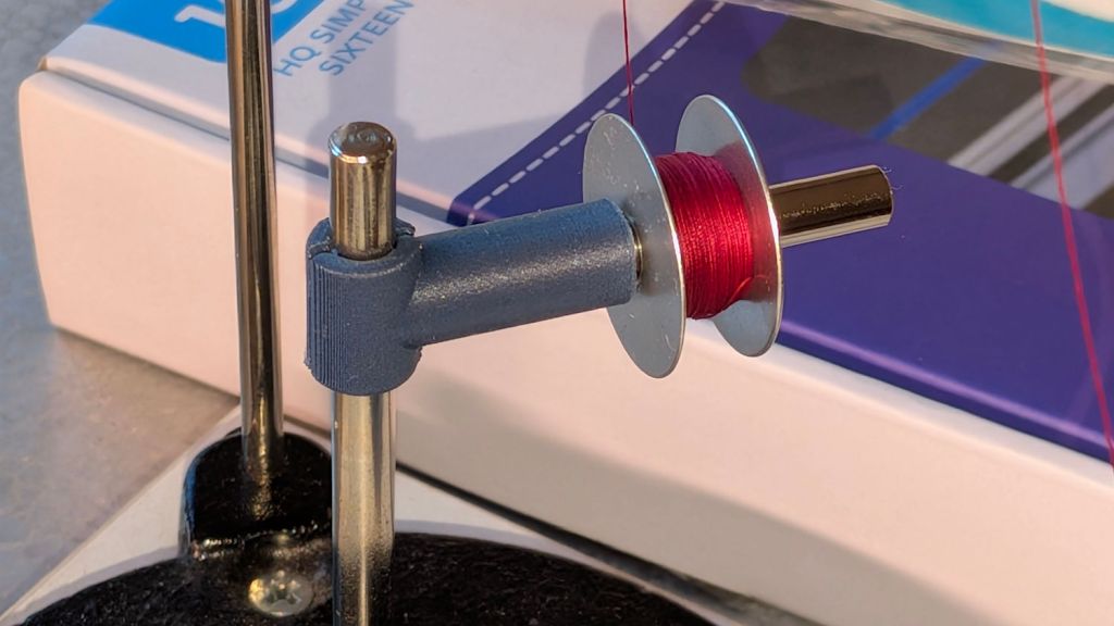
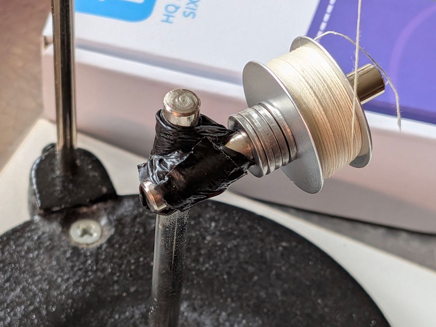
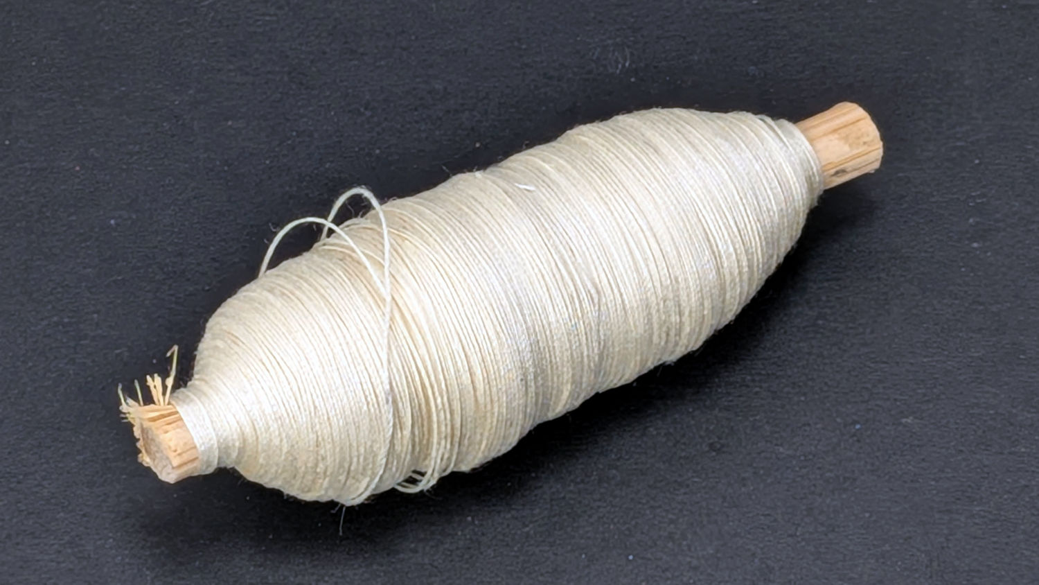
After filling two bobbins from a spool of the thread Mary uses for practice quilts, I decided I should reuse the thread. Mounting the filled bobbin on a 6 mm horizontal shaft attached to the vertical pin normally locating the spool let the thread pay out in the proper orientation, with a duct-tape lashup holding the shaft in place:
HQ Sixteen bobbin unwind adapter – expedient version
I added the stack of washers to keep the bobbin away from the duct tape after having the tape’s adhesive migrate onto the spinning bobbin.
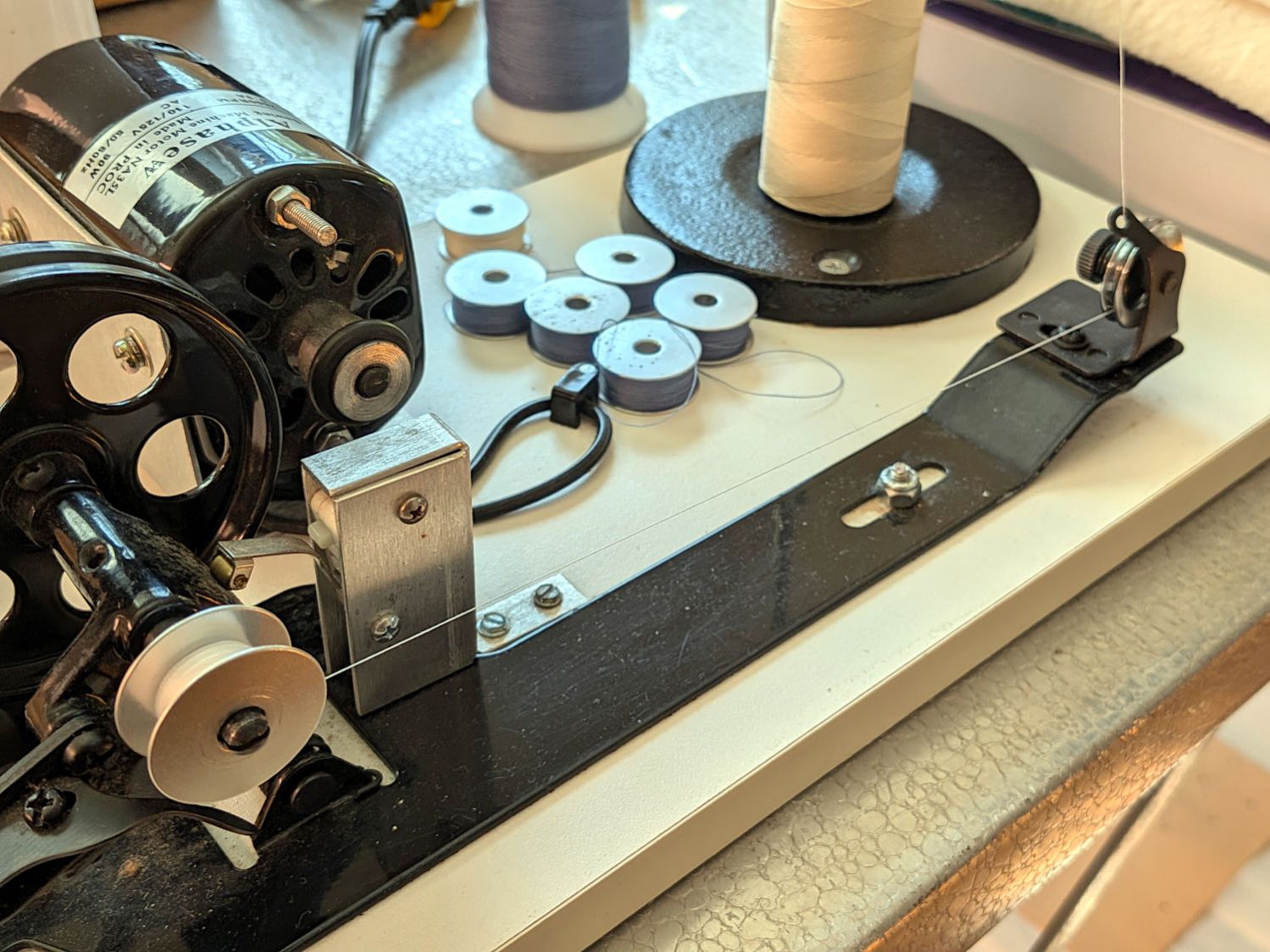
The thread from the spool or, in my case, a filled bobbin, passes between a pair of tension disks on its way to the bobbin spun by the motor:
HQ Sixteen bobbin winder – thread path
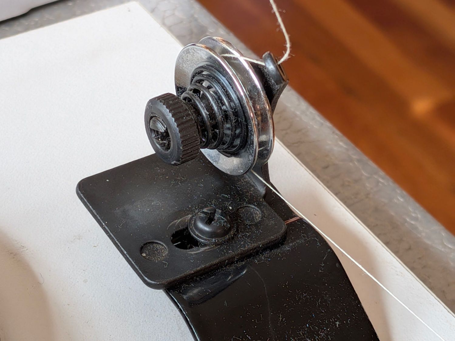
A conical spring presses the tension disks together, with the thread clamped between them:
HQ Sixteen bobbin winder – tension disk overview
The instructions suggest using “the lightest tension possible”, but backing the nut off to hang by its fingernails had no effect. The spring has a bent end passing through the slotted shaft, so rotation of the disks won’t unscrew the nut.
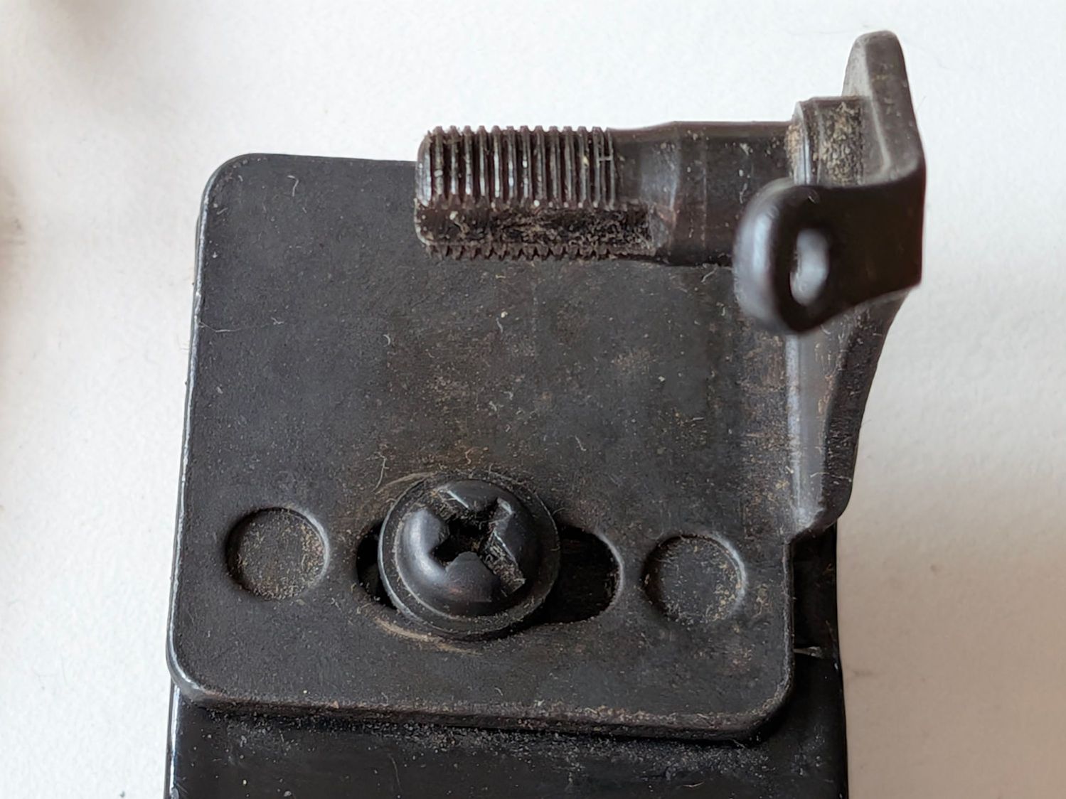
The washer under the mounting screw left slight scars in the black oxide finish on the fixture, presumably from previous attempts to adjust the thing:
HQ Sixteen bobbin winder – tension disk base
The threaded shaft is not exactly parallel to the base, because the upright arm is slightly over-bent, but I think that has no effect on the outcome, because the thread path doesn’t depend on the disk angle.
Because the thread accumulated on the outer side of the bobbin (to the right in that picture), I loosened the mounting screw and shoved the fixture all the way to the left. That should, if anything, bias the thread accumulation to the other (inner) side of the bobbin.
As it turned out, relocating the tension disks caused the thread to distribute evenly across the bobbin, with only occasional hesitations and no significant accumulations; Mary pronounced the result entirely satisfactory.
The motor dataplate says it runs at 7000 RPM, so the 3/4 inch O-ring drives the 4 inch wheel at about 1300 RPM. This was sufficiently terrifying I immediately set up a triac speed control (intended for a router) to throttle it down, but with the bobbins now filling properly we run the motor at full speed and it fills a bobbin in 23 seconds flat.
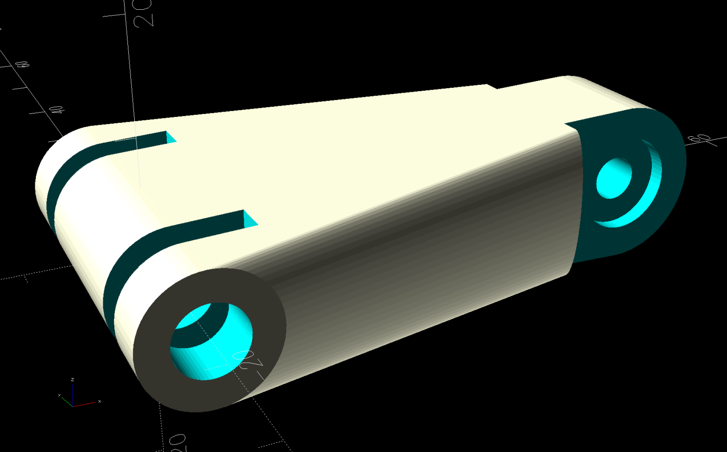
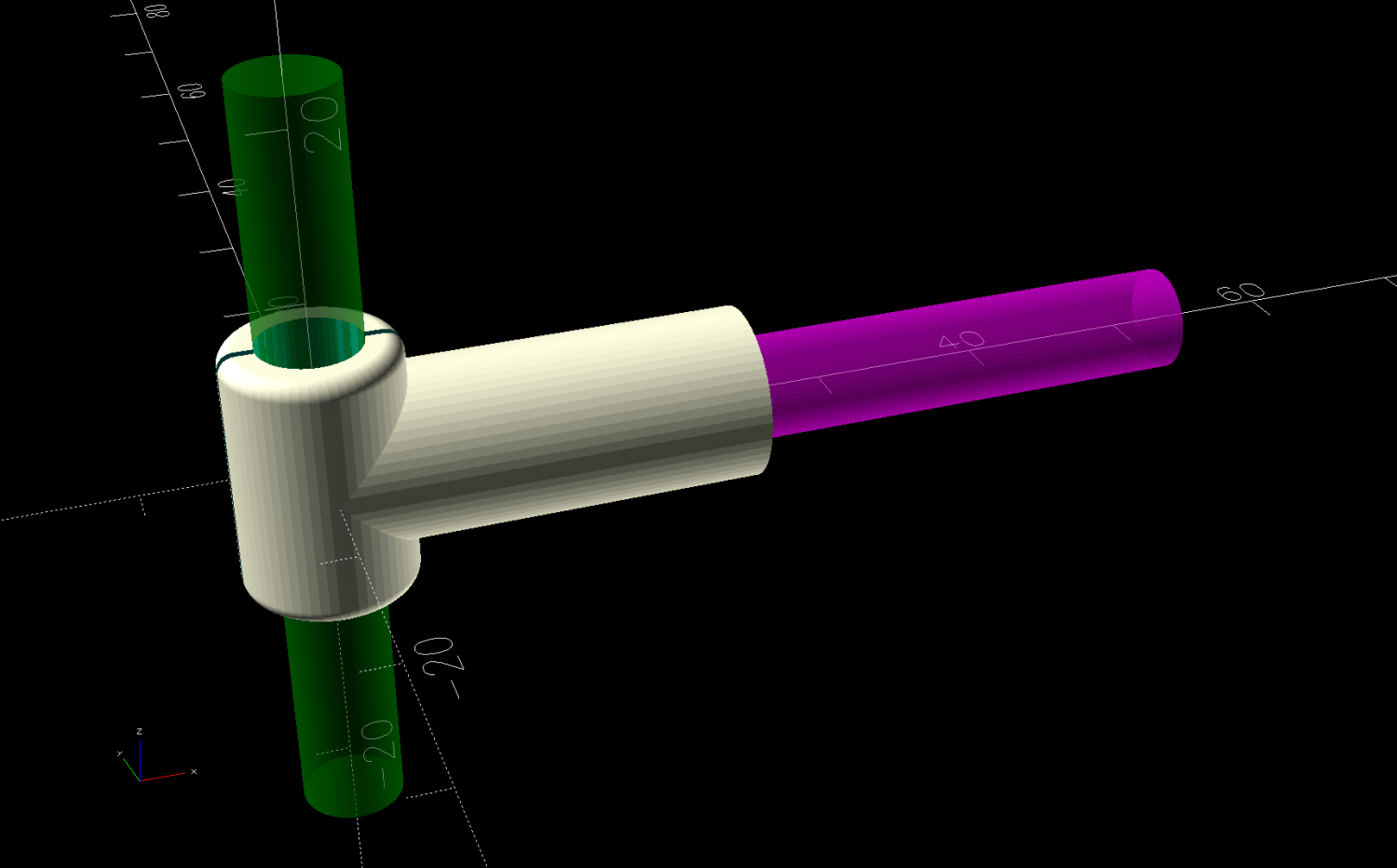
After we filled half a dozen bobbins with blue thread for the quilt project, I conjured an adapter from the vasty digital deep for a snippet of 6 mm rod with a D-shaped end:
Bobbin Unwind Adapter – solid model – show
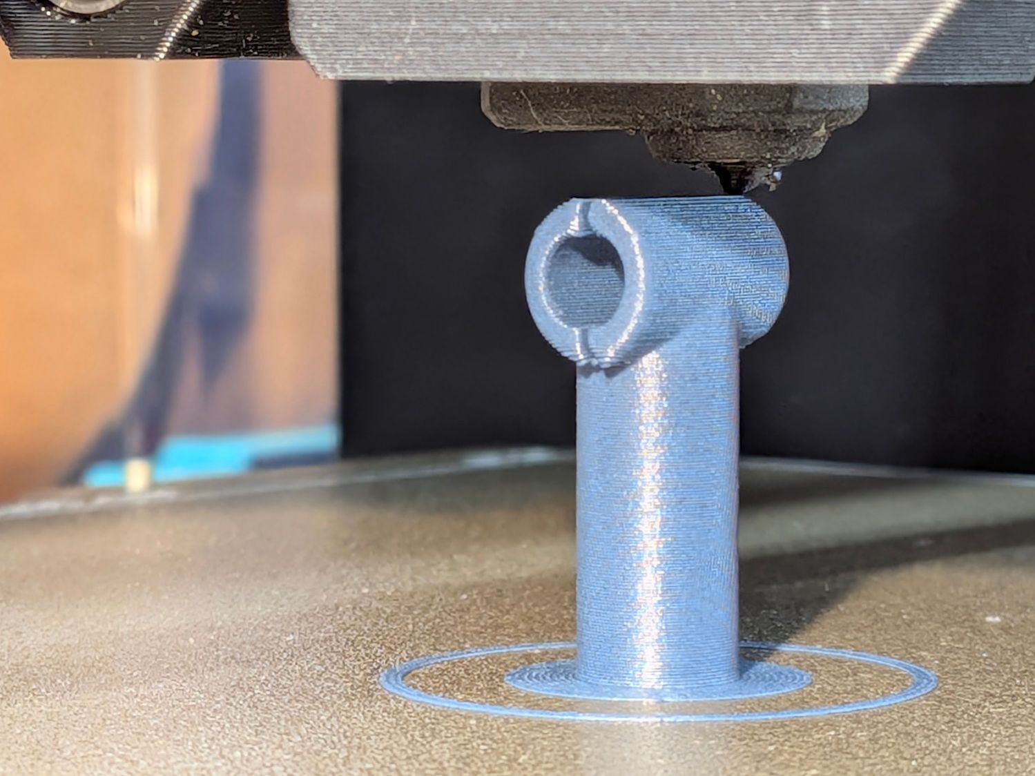
The adapter builds on one leg, with a brim for stability:
HQ Sixteen bobbin unwind adapter – on platform
And looks like it belongs there:
HQ Sixteen bobbin unwind adapter – installed
It’s now in the box of HQ Sixteen bobbins, where we both hope it will remain undisturbed forevermore.
Although the vertical pin locating the spools (and holding the adapter) is nominally 6 mm, burrs in the chrome plating prevented the bobbin’s 6 mm bore from sliding over it. In retrospect, that prevented me from just dropping the bobbin on the pin and unwinding the thread over the side of the bobbin, which likely avoided some serious-to-lethal thread tangles.
After all that debugging, I had several bobbins full of well-worn thread, so:
This file contains hidden or bidirectional Unicode text that may be interpreted or compiled differently than what appears below. To review, open the file in an editor that reveals hidden Unicode characters.
Learn more about bidirectional Unicode characters
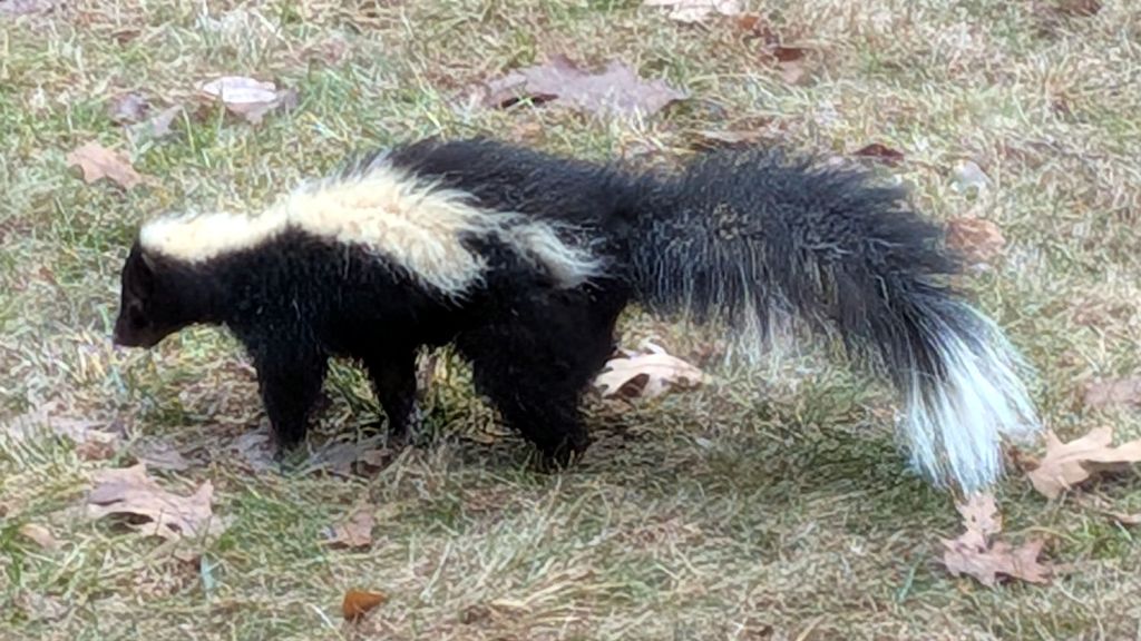
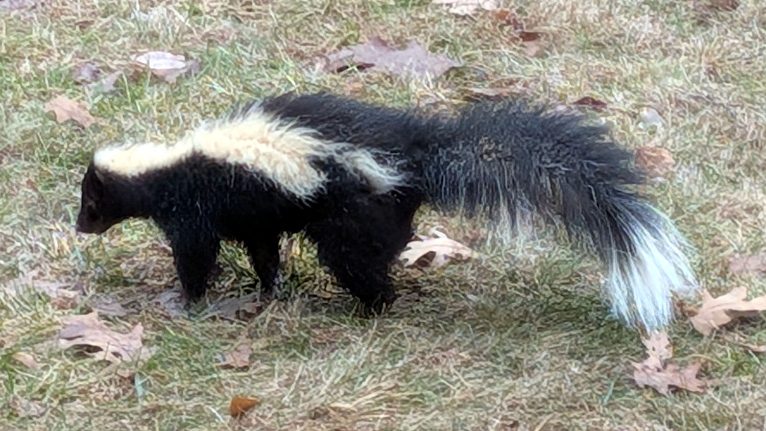
Skunks are generally crespecular animals, so seeing this critter in broad daylight was unusual:
Sickly Skunk
That’s taken through two layers of half-century old glass, for obvious reasons.
What may not be obvious: that skunk was not behaving at all like the ones in our previous sightings. It had unkempt fur, staggered around the house twice while twitching uncontrollably, slumping face-down, and falling on its side. I am not qualified to diagnose animal diseases, but rabies seems likely.
It eventually staggered off and, we hope, died quietly in a very secluded spot.
The Town of Poughkeepsie’s Animal Control officer now specializes in dog problems across several towns, with “all other animals” handled by the county’s Department of Health.
After approximately forever, the shackle on the Corbin K436 padlock securing the tandem-length cable we use for the Tour Easy ‘bents refused to push into the body. Lubrication being unavailing, I soaked it in acetone and shook it around for a day to get the inevitable crud out, then pondered the problem.
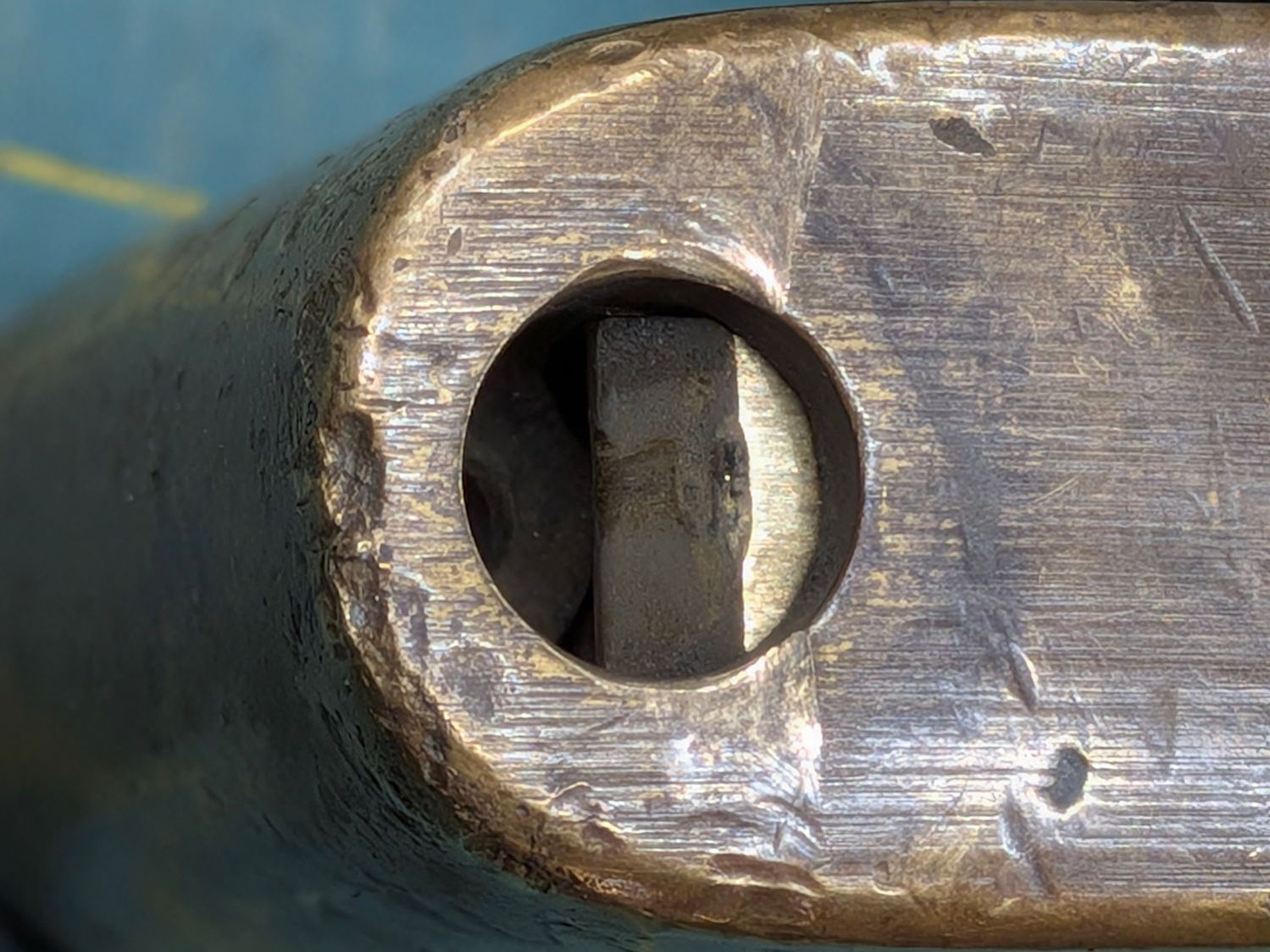
Peering into the hole where the shackle enters the body showed the situation:
Corbin padlock – cam damage
Half a century (more or less: it didn’t accumulate those nicks & dings & tarnish last year) of pushing the shackle into the lock eroded the locking cam, to the extent that the cam no longer slides sideways to let the shackle slide the rest of the way into the body.
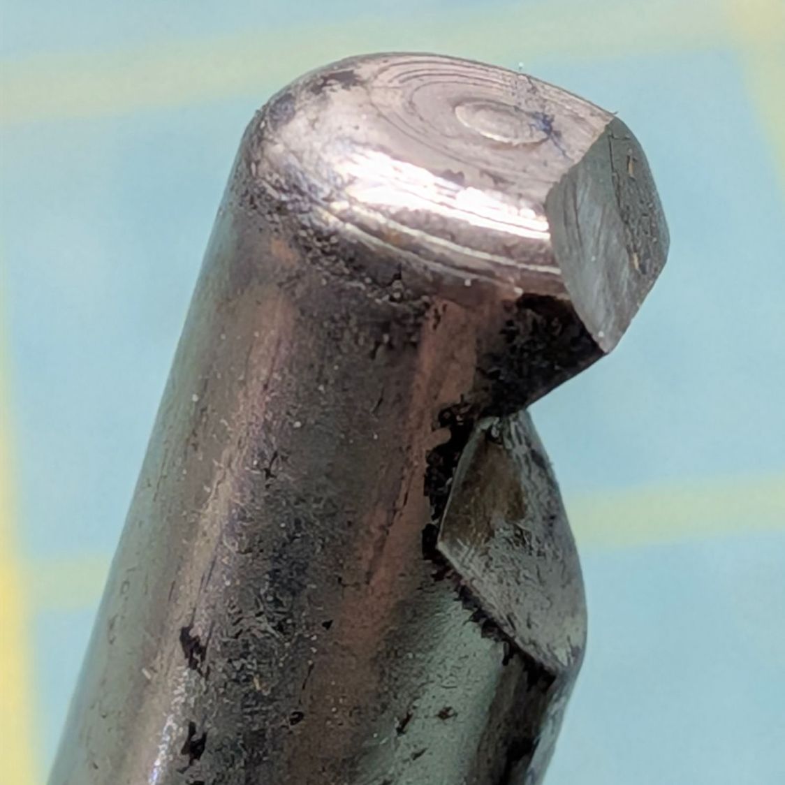
So I introduced the shackle to Mr Bench Grinder and reshaped the end to hit the cam farther down on its angled side:
Corbin padlock – reshaped shackle
While that certainly reduces the strength of the shackle, there’s a similar notch engaging a similar cam on the other end of the shackle, so it remains as secure as it must be for our simple needs.
Spraying silicone lube into the body and applying a dab of silicone grease to the cam restored the lock to (nearly) new condition.