Ed Nisley's Blog: Shop notes, electronics, firmware, machinery, 3D printing, laser cuttery, and curiosities. Contents: 100% human thinking, 0% AI slop.
Mary bought a pair of Revlon tweezers a while ago, picking a Name Brand to avoid hassles with bottom-dollar crap:
Revlon tweezers – bad spot welds
Well, that didn’t work.
I contend that the only difference between Name Brands and the bottom-dollar crap I tend to buy is a bit of QC and a lot of price. I’ll agree that’s not strictly true, but it does fit a goodly chunk of the observed data.
Anyhow.
I milled a recess into the corner of some scrap plastic to locate the handle end, then arranged a step block to capture the business end:
Revlon tweezers – drilling setup
That setup ensures the holes go into the corresponding spots on both pieces, because I couldn’t figure out how to clamp them together and drill them both at once. I drilled the other piece with its good side up to align the holes; doing it bad side up would offset the holes if they’re not exactly along the center line.
A closer look:
Revlon tweezers – drilling fixture
Talk about a precarious grip on the workpiece!
I filed the welds flat before drilling, so the pieces lay flat and didn’t distract the drill.
Then:
Center-drill
Drill 2-56 clearance
Scuff up mating surfaces with coarse sandpaper
Apply epoxy
Insert screws
Add Loctite
Tighten nuts to a snug fit
Align jaws
Tighten nuts
Fine-tune jaw alignment
Apply mild clamping force to hold jaws together
Wait overnight
Saw screws and file flush
Done!
The clamping step:
Revlon tweezers – epoxy curing
Those nicely aligned and ground-to-fit jaws were the reason Mary bought this thing in the first place.
The screw heads look OK, in a techie sort of way:
Revlon tweezers – fixed – front
The backside won’t win any awards:
Revlon tweezers – fixed – rear
But it won’t come apart ever again!
There’s surely a Revlon warranty covering manufacturing defects, printed on the long-discarded packaging, that requires mailing the parts with the original receipt back to some random address at our own expense.
Most technical papers intended for publication in Refereed Journals have huge margins. When I print them up as pamphlets for E-Z reading in the Comfy Chair, the text becomes an unreadably small block in the middle of the page.
Having tried various simple hacks that don’t work, the best solution so far involves a bit of PostScript magic…
Which will emit whatever-crop_book.pdf. Print the odd pages, reinsert the stack, print the even pages, then either fold or slice/bind as appropriate.
The --margins 36 puts a little whitespace around the text, which may be needed to get the text block out of the gutter if you’re binding the booklet. For those documents, --margins "36 0 18 0" may be more useful; note the blanks, not commas. This requires tuning for best picture, depending on the incoming PDF layout.
The -origpagesizes prevents the next step from assuming an incorrect page size. This is definitely necessary, at least in my experience so far.
The -f 1 enlarges the source text to fill the output page, which is the key step making the whole thing work for small incoming page sizes. However, there’s a weird interaction between this and the pdfcrop margins that I haven’t figured out yet; a zero-width incoming margin [may | may not] jam some line ends against the right edge of the output sheet.
The R380 emits pages bassackwards for reading, but in the proper order for duplexing: the blank side of the first sheet is on the bottom of the stack, so it becomes the top of the flipped stack, ready to go back into the printer as the first sheet again.
Conversely, the HPLJ1200 produces output in normal reading order, with the blank side of the last sheet on top of the stack: flip and print the back sides in reverse order.
I’d have trouble faking this with a straight face:
FT82-43 – 56 turns – 24 AWG
That’s measured with the 56 turn winding connected directly to a bench power supply, cranking up the current, taking the reading, and turning the current back down again, so as to avoid cooking the poor thing inside its PLA armor:
FT82-43 toroid – mounted
The “49E” sensor came from one of the bags of eBay fallout. They saturate around 4.25 V; the outputs above 4 V lose their linearity due to the sensor, not ferrite saturation.
The original calculations guesstimates suggested 25 turns would produce full scale at 5 A, so 56 turns should top out at 2.2 A. Frankly, given all the imponderables in this lashup, a factor of two seems pretty close.
Offsetting the output by -1 A would yield a 2 A range that’s just about exactly right. Unfortunately, some fiddling about with neodymium magnets suggests that you (well, I) can’t stuff enough opposing field into the slit without saturating (some part of) the ferrite core, reducing the permeability, and blowing all the assumptions.
So that suggests a buck winding, obviously with more turns to allow less current for the same magnetizing force. Wrapping 110 turns reduces the buck current to 500 mA and assuming a bit over an inch/turn requires 10 feet, which is nearly 1 Ω of 30 AWG wire: the buck current dumps another 250 mW into (a somewhat larger version of) that PLA armor.
Or just throw away half of the Hall effect sensor range and use an op amp along the lines of the LED current sensor.
I didn’t bring the HDR-AS30V camera along on the Hudson River ride, simply because each battery lasts about 1.5 hr in 1920×1080 @ 60 fps mode and I wasn’t up to replacing batteries during the ride, then charging all three every evening. Obviously, the camera wasn’t intended for that use case.
Somewhat surprisingly, the Wasabi batteries deliver the same continuous run time as the Sony battery: 1:30 vs 1:33. I used 250 mA for those discharge curves, but I think something around 500 mA would better match the camera load.
I’m sorely tempted to drill a hole in the camera’s case and wire in a honkin’ big prismatic lithium cell.
These sunglasses fit Mary’s face and do a good job of keeping road grit out of her eyes, but she doesn’t like the extended earpieces. So I cut ’em off:
Ironman sunglasses – trimmed earpieces
The trick is to shape the ends with an ordinary diagonal cutter, then round the edges with sandpaper.
The lower pair has seen a few years of use, during which the bright yellow plastic faded quite a bit.
Nothing profound, other than that you need not put up with nuisances.
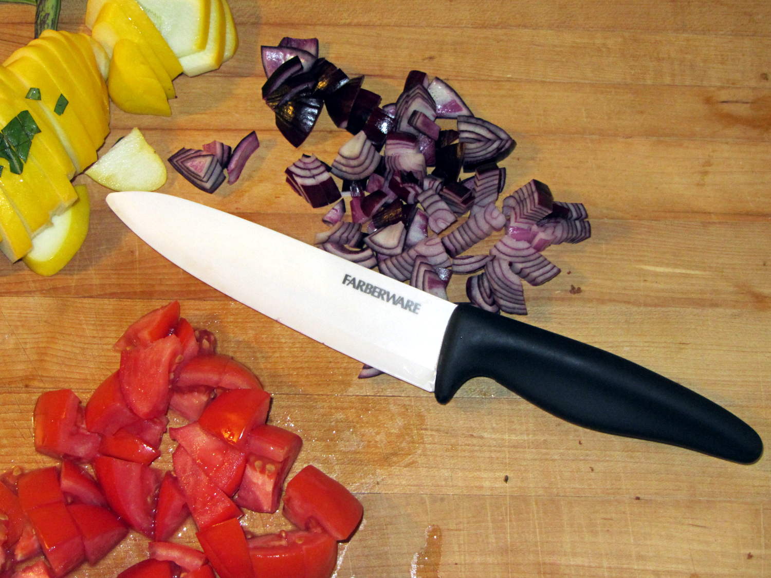
In these degenerate times, it seems anyone can just buy a crysknife:
Farberware ceramic knife
Admittedly, it lacks the original’s kinjal shape and curved blade. We once had a double-edged, serrated kitchen knife and I swore a mighty oath on the bones of my ancestors to never, ever make that mistake again.
Surprisingly, the plastic handle balances well with the ceramic blade: no need for another tungsten counterweight. The handle extends slightly below the blade’s heel, which may call for some abrasive adjustment.
The blade is slightly thicker than the wonderful steel santokuknives we’ve been using forever and doesn’t taper uniformly from spine to edge, so it’s no good for constrained cutting (like quartering an apple). The hollow-ground section behind the edge forms a wedge that cracks apples apart, unlike the santoku’s full-width taper that just slides right through.
I was mildly surprised to find that it’s no sharper (perhaps that’s “no more keen”) than our steel knives, but, then, I’m wicked with the sharpening steel. The edge arrived minus a few tiny chips and I suspect we’ll add more in normal use, right up to the moment when one of us drops it on the floor.
A gotcha: that blade’s eyeblink affordance is harmless plastic. I must remind myself it’s a real knife with a lethally sharp edge.
Thus far, we’ve sheathed the blade unblooded, in clear violation of the Fremen ritual. May it ever be so…
Given the fragility of ferrite toroids in general and slit toroids in particular, a touch of up-armoring seems sensible:
FT82-43 toroid – mounted
The solid model includes a toroid shell with roughly the right curves:
Toroid Mount – Show layout
That puts a nice rounded shape on the bottom of the armor, not that that makes much difference:
Toroid Mount – Build layout
The central hole passes a 4-40 brass, nylon, or stainless steel screw. Most of the magnetic field stays within the ferrite and, heck, this isn’t a crazy-sensitive analog application, so even an ordinary steel screw shouldn’t cause any particular problems.
The rectangular (not pie-wedge) slit barely passes the Hall effect sensor.
I’ll pour some clear epoxy over the toroid, with tape masking the ferrite core and sealing the ends, to immobilize the windings. That sounds like a good idea after calibration and suchlike.
The OpenSCAD source code, which should be sufficiently parametric that I can crank ’em out for all the other toroids large enough to accept a screw:
// Toroid coil mounting bracket
// Ed Nisley - KE4ZNU - August 2014

Layout = "Mount";			// Coil Mount Build Show

//- Extrusion parameters must match reality!
//  Print with 4 shells and 3 solid layers

ThreadThick = 0.20;
ThreadWidth = 0.40;

HoleWindage = 0.2;			// extra clearance

Protrusion = 0.1;			// make holes end cleanly

AlignPinOD = 1.70;			// assembly alignment pins: filament dia

function IntegerMultiple(Size,Unit) = Unit * ceil(Size / Unit);

//----------------------
// Dimensions

ID = 0;												// subscripts for cylindrical objects
OD = 1;
LEN = 2;

Coil = [10.25,23.50,8.3];							// wound toroid core

SensorThick = 2.0;

BaseThick = IntegerMultiple(1.0,ThreadThick);		// baseplate under coil
WallThick = IntegerMultiple(1.0,ThreadWidth);		// walls beside coil

ScrewHoleDia = 4.0;									// allow alignment slop around 3 mm / #4 screws

//----------------------
// Useful routines

module PolyCyl(Dia,Height,ForceSides=0) {			// based on nophead's polyholes

  Sides = (ForceSides != 0) ? ForceSides : (ceil(Dia) + 2);

  FixDia = Dia / cos(180/Sides);

  cylinder(r=(FixDia + HoleWindage)/2,
           h=Height,
           $fn=Sides);
}

module ShowPegGrid(Space = 10.0,Size = 1.0) {

  RangeX = floor(100 / Space);
  RangeY = floor(125 / Space);

	for (x=[-RangeX:RangeX])
	  for (y=[-RangeY:RangeY])
		translate([x*Space,y*Space,Size/2])
		  %cube(Size,center=true);

}

//----------------------
// Basic coil shape

module CoilShape() {

CornerRadius = min((Coil[LEN] / 2),((Coil[OD] - Coil[ID]) / 2))  / 3;
MidRadius = (Coil[ID] + Coil[OD]) / 4;
HalfX = (Coil[OD] - Coil[ID]) / 4 - CornerRadius;
HalfY = (Coil[LEN] / 2) - CornerRadius;

echo(CornerRadius,MidRadius,HalfX,HalfY);

	color("Goldenrod")
	render(convexity = 2)
		rotate(180/20)
			rotate_extrude(convexity=3,$fn=20)
				translate([MidRadius,0])
					hull()
						for (i=[-1,1],j=[-1,1])
							translate([i*HalfX,j*HalfY])
								circle(r=CornerRadius,$fn=24);
}

//----------------------
// Mount

module Mount() {

	difference() {
		rotate(180/20)
			cylinder(h=(BaseThick + Coil[LEN]),d=(Coil[OD] + 2*WallThick),$fn=20);

		translate([0,0,-Coil[LEN]])							// make screw hole
			rotate(180/6)
				PolyCyl(ScrewHoleDia,3*Coil[LEN],$fn=6);

		translate([0,0,BaseThick + Coil[LEN]/2])			// set bottom curve
			CoilShape();

		translate([0,0,BaseThick + Coil[LEN]])				// clear out top
			CoilShape();

		translate([(Coil[ID]/2 + Coil[OD]/2),0,0])
			cube([Coil[OD],SensorThick,3*Coil[LEN]],center=true);
	}
}


ShowPegGrid();

if (Layout == "Coil") {
	CoilShape();
}

if (Layout == "Mount")
	Mount();

if (Layout == "Show") {
	Mount();
	translate([0,0,(BaseThick + Coil[LEN]/2)])
		CoilShape();
}


if (Layout == "Build") {
	Mount();
}