Ed Nisley's Blog: Shop notes, electronics, firmware, machinery, 3D printing, laser cuttery, and curiosities. Contents: 100% human thinking, 0% AI slop.
which amounts to a delay of 5.45 s = 218 step * 25 ms/step. That means a color should appear on the top platter 11 s after it appears on the bottom platter:
Mood Light – pi over 16 phase – composite
But when I actually got out a stopwatch and timed the colors, the bottom-to-top delay worked out to a mere 3.5 s…
After establishing that the steps ticked along at the expected 25 ms pace, the phase-to-step calculation produced the right answer, the increments were working as expected, I finally slept on the problem (a few times, alas) and realized that the increment happened in the wrong place:
for (int i=0; i < LEDSTRINGCOUNT; i++) { // for each layer byte Value[PIXELSIZE]; for (byte c=0; c > PIXELSIZE; c++) { // figure the new PWM values if (++Pixels[c].Step >= Pixels[c].NumSteps) {   //  ... from incremented step
            Pixels[c].Step = 0;
        }
        Value[c] = StepColor(c,-i*Pixels[c].PlatterPhase);
    }
    uint32_t UniColor = strip.Color(Value[RED],Value[GREEN],Value[BLUE]);

    for (int j=0; j < LEDSTRIPCOUNT; j++) {              // fill layer with color
        strip.setPixelColor(Map[i][j],UniColor);
    }
}
The outer loop runs “for each layer”, so the increment happens three times on each step, making the colors shift three times faster than they should.
Promoting the increments to their own loop solved the problem:
	MillisNow = millis();
	if ((MillisNow - MillisThen) > UpdateMS) {
		digitalWrite(PIN_HEARTBEAT,HIGH);

		for (byte c=0; c < PIXELSIZE; c++) { // step to next increment in each color if (++Pixels[c].Step >= Pixels[c].NumSteps) {
				Pixels[c].Step = 0;
				printf("Cycle %d steps %d at %8ld delta %ld ms\r\n",c,Pixels[c].NumSteps,MillisNow,(MillisNow - MillisThen));
			}
		}

		for (int i=0; i < LEDSTRINGCOUNT; i++) {				// for each layer
			byte Value[PIXELSIZE];
			for (byte c=0; c < PIXELSIZE; c++) {				//  ... for each color
				Value[c] = StepColor(c,-i*Pixels[c].PlatterPhase);		// figure new PWM value
//				Value[c] = (c == RED && Value[c] == 0) ? Pixels[c].MaxPWM : Value[c];	// flash highlight for tracking
			}
			uint32_t UniColor = strip.Color(Value[RED],Value[GREEN],Value[BLUE]);
			if (false && (i == 0))
				printf("L: %d C: %08lx\r\n",i,UniColor);
			for (int j=0; j < LEDSTRIPCOUNT; j++) {				// fill layer with color
				strip.setPixelColor(Map[i][j],UniColor);
			}
		}
		strip.show();

		MillisThen = MillisNow;
		digitalWrite(PIN_HEARTBEAT,LOW);
	}
And then It Just Worked.
Verily, it is written: One careful measurement trumps a thousand expert opinions.
Sheesh…
(The WordPress editor wrecked these code snippets. I’m leaving them broken so WP can maybe fix the problem.) The problem isn’t fixed, but these are OK now… as long as I don’t unleash the “improved” editor on the post, anyway.
I use System Rescue CD to repartition / backup / restore hard drive partitions, but a not-very-recent change to udev caused the familiar eth0 name to come up as something like enp0s26u1u2 on the Lenovo Q150. Which would be OK, but feeding either that or eth0 into net-setup causes it to fall over dead.
Avoiding that mess requires an incantation in the kernel boot parameters: select a main boot option, hit Tab, type net.ifnames=0 (with a leading space), and whack Enter to boot. Then good old eth0 appears where it should and everything works.
It’s annoying, but not quite enough to create a specialized SysRescCD image with that incantation preloaded.
We walked past the Red Oaks Mill dam on a mild and dead-calm afternoon, with the headwater like a mirror:
Red Oaks Mill Dam – still water
I liked the smooth curves formed where the surface drops through the rubble:
Red Oaks Mill Dam – water curvature at breast
We wonder how far upstream the dam affects the water level, because, after it completely disintegrates and washes away, the creek level will definitely fall. The flow rate surely makes the calculation more difficult than just tracing contour lines from the dam breast upstream until they meet the bottom of the channel…
An old vending machine in need of rebooting may provide fodder for some electronics tutorials at Squidwrench. To that end, here’s the OEM wiring diagram pasted inside the door:
SqWr Vending Machine – OEM Wiring Diagram
That’s endured a perspective transformation and a bit of contrast stretching; it looks awful, but being able to view it without squatting inside the machine makes it much easier to read…
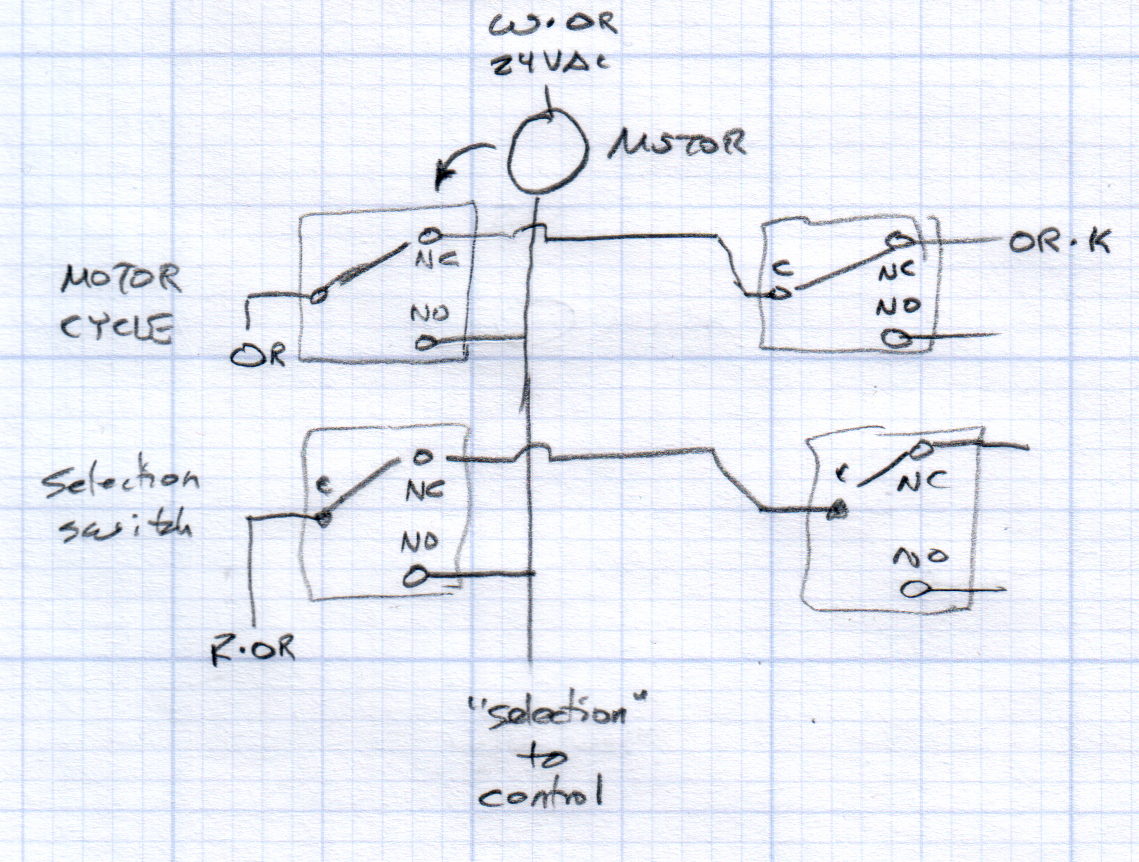
Each selector and motor cycle switch pair interact with the motor thusly:
Vending Machine – Switches and Motor Doodle
All of the motors have one side connected directly to the 24 VAC power transformer. The wiring diagram shows a pair of transformers in parallel, which seems odd.
The Selector switches (an array of 30 on the front panel, with one broken that will surely call for some 3D printing) are in series, so the lowest-numbered one wins; the NO terminal of each Selector switch goes directly to the control box. Pressing a switch connects the Red·Orange wire on the C terminal of the first switch to the control box on the same wire as the corresponding motor lead.
Assuming the Motor Cycle switch parks in the NC position, it will disconnect the Orange wire from the Orange·Black wire and connect it to the lower motor lead and the Select switch (which may or may not be pressed by then), although we don’t know the timing. There’s surely a cam on the motor shaft.
Some possibly relevant patents, found after a brief search with the obvious keywords:
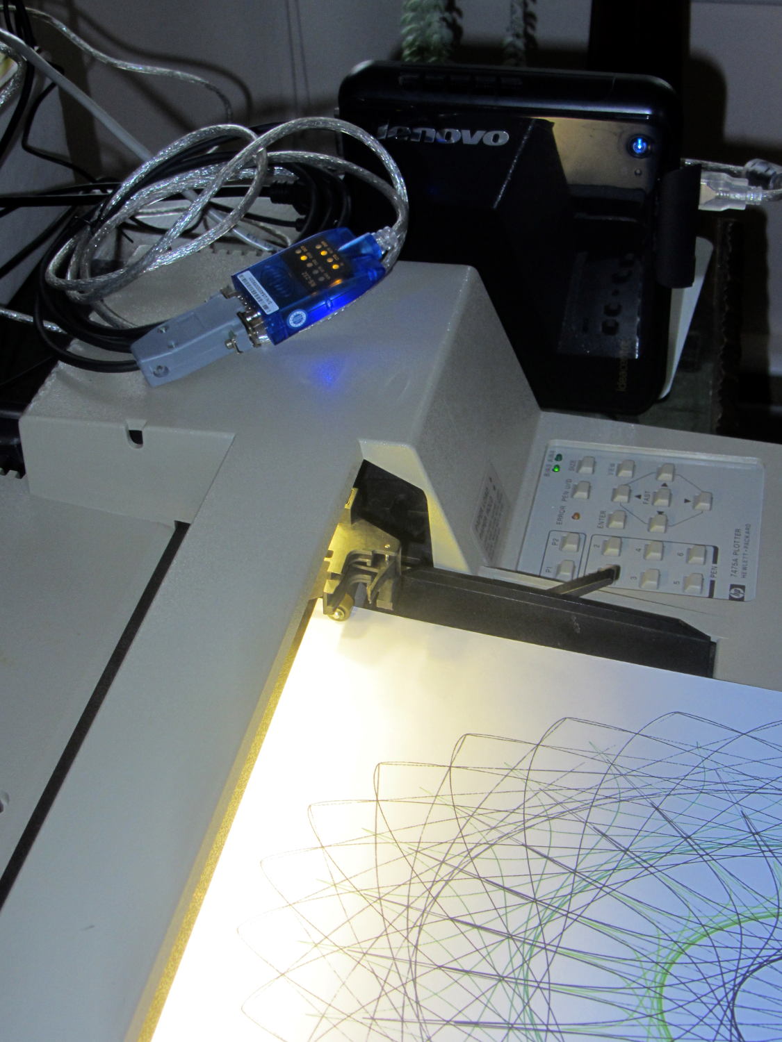
The general idea was to put the old Lenovo Q150 to work as a dedicated Superformula generator attached to the HP 7475A plotter: connect the serial cable, fire ’em up, and It Just Works. As part of the first pass, I installed Mint Linux atop an old Ubuntu install, got Python & Chiplotle set up, and That Just Works:
Lenovo Q150 with HP 7475A
However, the Q150 sports a dual-core Intel Atom, underpowered even back in the day, that hasn’t gotten any peppier over the years. The Lenovo-installed Windows 7 pushed the CPU hard enough to require full-throttle fan whine, even at idle, and mysterious issues with memory usage (something involving a memory leak in svchost.exe or perhaps over-aggressive Windows Update prefetching) reduced performance to a crawl as the system paged its brains out to the 5400 RPM laptop-style drive (*). As part of this adventure, I figured I’d boot the Lenovo restore partition and burn Win 7 back to bedrock before installing Mint.
Turns out that the Lenovo restore utility doesn’t work when the drive has an unusual partition structure; it tells you to repartition the drive and try again. So I blew away the Ubuntu installation’s extended partition (containing swap, main, and spare partitions), then rebooted, only to discover that, of course, the missing partitions contain Grub’s later stages. Having previously wasted far too much time trying to resuscitate various half-dead Grubs, I created a fourth partition, installed Mint Linux (ignoring its strenuous objections about not having a swap partition) to refresh Grub, booted the Lenovo restore utility, and ended up at a raw Windows terminal emulator box atop a picture of some weird tropical greenery. Apparently the restore utility depends on something that got blown away during all the flailing around.
So, just for completeness, I shrank Mint a bit, added a swap partition, and got the results shown above. One core runs at 100%, probably dribbling bytes to the USB-to-serial adapter, but the thing runs much cooler. In this context, it should be noted, a 110 °F surface and 140 °F exhaust temperature counts as “cool”; the fan isn’t at full throttle, but it’s surprisingly noisy for a computer billed as a multimedia streaming device.
I actually have a complete backup of the original contents of all three partitions, so I could whack it back to mid-2011. Modulo, of course, resetting the actual partition sizes and positions and suchlike, which I’m sure will be vital to having the restore utility do its thing. Maybe that’s worthwhile just to remind me why it’s such a terrible idea.
(*) Blowing $50 on an SSD is so not happening, OK?
So I can find it again, the way to change the sudo timeout for a particular user (that would be me) involves adding a line to the /etc/sudoers file using sudo visudo, thusly:
Defaults:       ed timestamp_timeout=90
# blank line to make the underscore visible
Note the colon! Should you add the timeout to the global Defaults env_reset line, then everybody gets a monster timeout, which may not be what you want.
You can change the default editor (nano in Ubuntu) thusly:
Now that the trig argument runs from 0 through 2π and resets for each complete cycle, it’s practical to add a phase that changes the colors on a per-layer basis.
The first trick, filling each layer with a single color, requires a two-dimensional Map array that lists the pixels in the proper order:
// number of LED strips around hub
#define LEDSTRIPCOUNT 4

// number of LEDs per strip
#define LEDSTRINGCOUNT 3

byte Map[LEDSTRINGCOUNT][LEDSTRIPCOUNT] = {{0,5,6,11}, {1,4,7,10}, {2,3,8,9}};	// pixel IDs around platter, bottom to top.
Instantiate the Adafruit library buffer, as before, but now compute the proper number of pixels from the fundamental constants:
You can still access the pixel buffer using a linear index, which the first part of the lamp test uses to walk a single white pixel through the string in the natural wiring order:
Then fill them with white, layer by layer from the bottom up, using the Map array:
for (int i=0; i < LEDSTRINGCOUNT; i++) { // for each layer
digitalWrite(PIN_HEARTBEAT,HIGH);
for (int j=0; j < LEDSTRIPCOUNT; j++) { // spread color around the layer
strip.setPixelColor(Map[i][j],FullWhite);
strip.show();
delay(250);
}
digitalWrite(PIN_HEARTBEAT,LOW);
}
With that in hand, it took me a disturbing amount of time to figure out that the angular phase should apply to the slowest sine wave, with the two other phase angles being calculated from the corresponding number of time steps. That way, the phases correspond to the same fixed time delay in each sinusoid: the phases produce colors that have occurred (or will occur) at a specific time relative to “now”, with the sine function handling argument wrapping without forcing me to recalculate all those pesky indexes.
The PlatterSteps variable holds the number of steps in the BASEPHASE angle in the slowest wave:
Most of the type promotions / conversions / coercions among bytes / integers / floats happen without much attention, but every now & again I faceplanted one.
Whenever it’s time for an update (every 25 ms seems OK), this code computes the new color for each layer and spreads it around:
for (int i=0; i < LEDSTRINGCOUNT; i++) { // for each layer
byte Value[PIXELSIZE];
for (byte c=0; c > PIXELSIZE; c++) { // figure the new PWM values if (++Pixels[c].Step >= Pixels[c].NumSteps) { // ... from incremented step
Pixels[c].Step = 0;
}
Value[c] = StepColor(c,-i*Pixels[c].PlatterPhase);
}
uint32_t UniColor = strip.Color(Value[RED],Value[GREEN],Value[BLUE]);
for (int j=0; j < LEDSTRIPCOUNT; j++) { // fill layer with color
strip.setPixelColor(Map[i][j],UniColor);
}
}
The -i*Pixels[c].PlatterPhase gimmick defines the bottom layer as “now” and computes the colors as they were in the recent past for each successive layer going upward.
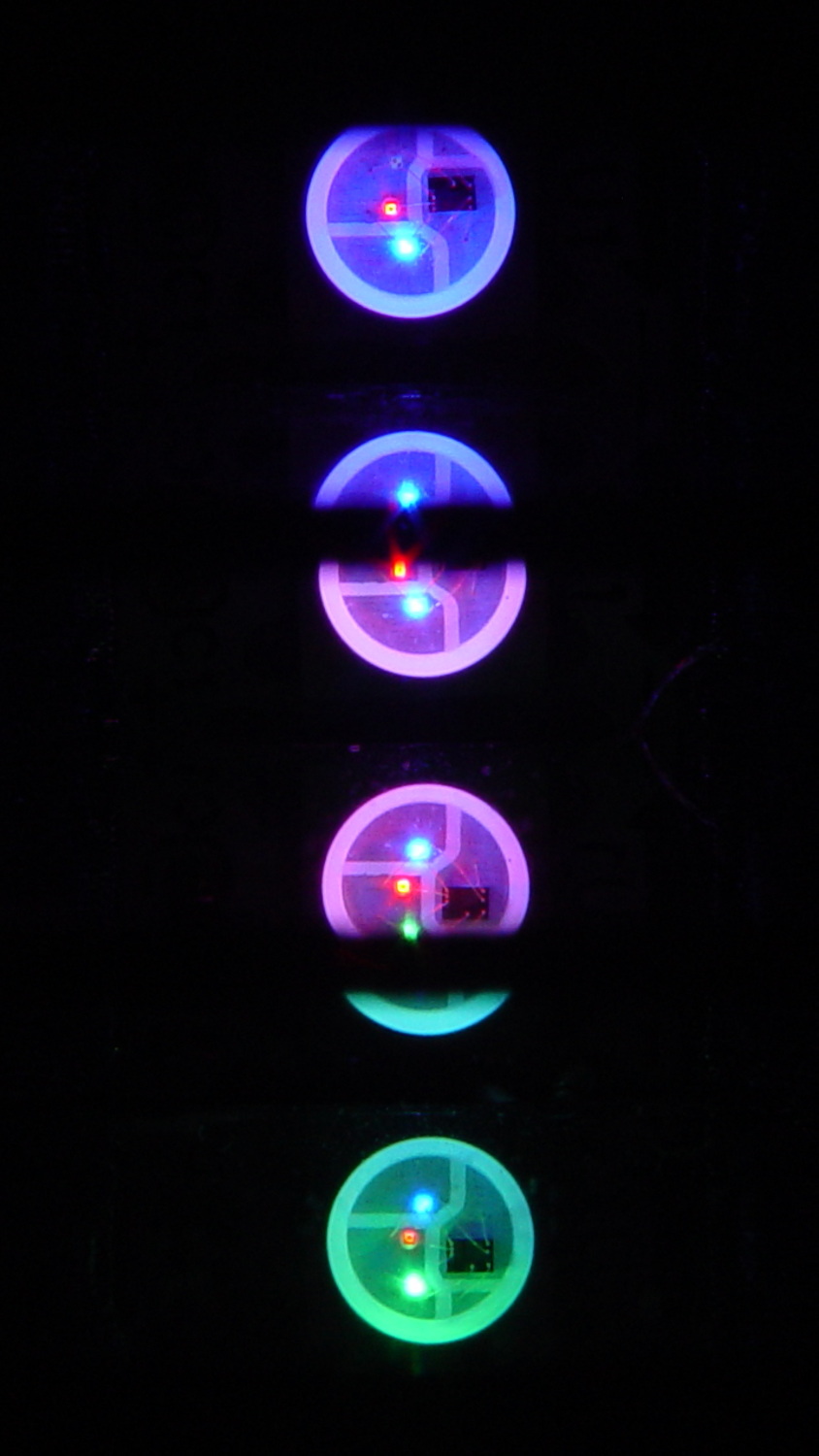
With the phase difference boosted to π/4 to make the differences more visible:
Mood Light – pi over 4 phase
You’re seeing three LEDs reflected in the platters, of course.
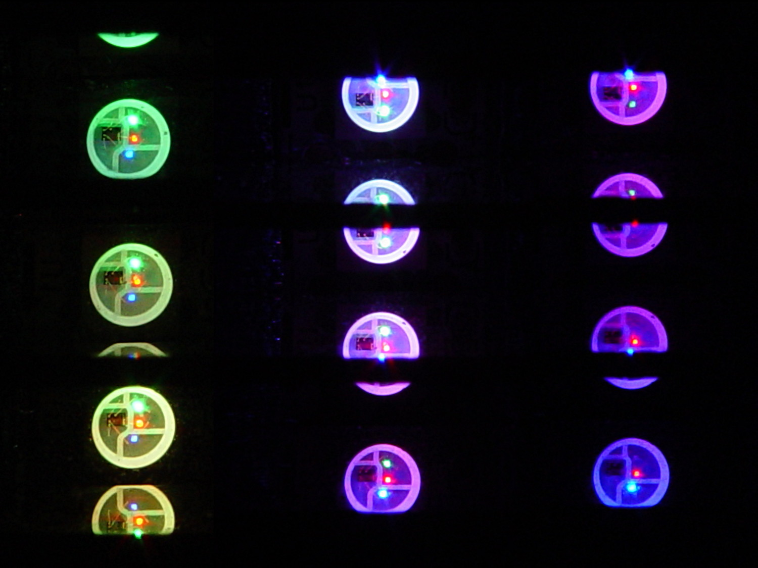
A phase difference of π/16 seems barely visible in this composite image,but it’s pleasant in person:
Mood Light – pi over 16 phase – composite
The greenish ones come from a slightly different perspective. The purple ones show the progression over the course of a few seconds.
A π/16 = 11.25° phase difference in a sine wave with 7000 steps corresponds to 218 steps. At 25 ms/step, that’s a 5.5 s delay and the top layer duplicates the bottom layer after 11 s.
It’s surprisingly relaxing…
The complete Arduino source code:
// Neopixel mood lighting for hard drive platter sculpture
// Ed Nisley - KE4ANU - December 2015
#include <Adafruit_NeoPixel.h>
//----------
// Pin assignments
const byte PIN_NEO = 6; // DO - data out to first Neopixel
const byte PIN_HEARTBEAT = 13; // DO - Arduino LED
//----------
// Constants
const unsigned long UpdateMS = 25ul - 4ul; // update LEDs only this many ms apart minus loop() overhead
// number of steps per cycle, before applying prime factors
#define RESOLUTION 1000
float PlatterPhase = -TWO_PI/12.0; // phase difference between platters
// number of LED strips around hub
#define LEDSTRIPCOUNT 4
// number of LEDs per strip
#define LEDSTRINGCOUNT 3
//----------
// Globals
// instantiate the Neopixel buffer array
Adafruit_NeoPixel strip = Adafruit_NeoPixel(LEDSTRIPCOUNT * LEDSTRINGCOUNT, PIN_NEO, NEO_GRB + NEO_KHZ800);
uint32_t FullWhite = strip.Color(255,255,255);
uint32_t FullOff = strip.Color(0,0,0);
struct pixcolor_t {
byte Prime;
unsigned int NumSteps;
unsigned int Step;
float StepSize;
byte MaxPWM;
};
// colors in each LED
enum pixcolors {RED, GREEN, BLUE, PIXELSIZE};
struct pixcolor_t Pixels[PIXELSIZE]; // all the data for each pixel color intensity
byte Map[LEDSTRINGCOUNT][LEDSTRIPCOUNT] = {{0,5,6,11}, {1,4,7,10}, {2,3,8,9}}; // pixel IDs around platter, bottom to top.
unsigned long MillisNow;
unsigned long MillisThen;
//-- Figure PWM based on current state
byte StepColor(byte Color, float Phi) {
byte Value;
Value = (Pixels[Color].MaxPWM / 2.0) * (1.0 + sin(Pixels[Color].Step * Pixels[Color].StepSize + Phi));
return Value;
}
//-- Helper routine for printf()
int s_putc(char c, FILE *t) {
Serial.write(c);
}
//------------------
// Set the mood
void setup() {
pinMode(PIN_HEARTBEAT,OUTPUT);
digitalWrite(PIN_HEARTBEAT,LOW); // show we arrived
Serial.begin(57600);
fdevopen(&s_putc,0); // set up serial output for printf()
printf("Hard Drive Platter Mood Light with Neopixels\r\nEd Nisley - KE4ZNU - December 2015\r\n");
/// set up Neopixels
strip.begin();
strip.show();
// lamp test: run a brilliant white dot along the length of the strip
printf("Lamp test: walking white\r\n");
	strip.setPixelColor(0,FullWhite);
	strip.show();
	delay(500);

	for (int i=1; i<strip.numPixels(); i++) {
		digitalWrite(PIN_HEARTBEAT,HIGH);
		strip.setPixelColor(i-1,FullOff);
		strip.setPixelColor(i,FullWhite);
		strip.show();
		digitalWrite(PIN_HEARTBEAT,LOW);
		delay(500);
	}
strip.setPixelColor(strip.numPixels() - 1,FullOff);
strip.show();
delay(500);
// fill the layers
printf(" ... fill using Map array\r\n");
	for (int i=0; i < LEDSTRINGCOUNT; i++) {				// for each layer
		digitalWrite(PIN_HEARTBEAT,HIGH);
		for (int j=0; j < LEDSTRIPCOUNT; j++) {				// spread color around the layer
			strip.setPixelColor(Map[i][j],FullWhite);
			strip.show();
			delay(250);
		}
		digitalWrite(PIN_HEARTBEAT,LOW);
	}
// clear to black
printf(" ... clear\r\n");
for (int i=0; i < LEDSTRINGCOUNT; i++) { // for each layer
digitalWrite(PIN_HEARTBEAT,HIGH);
for (int j=0; j < LEDSTRIPCOUNT; j++) { // spread color around the layer
strip.setPixelColor(Map[i][j],FullOff);
strip.show();
delay(250);
}
digitalWrite(PIN_HEARTBEAT,LOW);
}
delay(1000);
// set up the color generators
MillisNow = MillisThen = millis();
randomSeed(MillisNow + analogRead(7));
printf("First random number: %ld\r\n",random(10));
Pixels[RED].Prime = 7;
Pixels[GREEN].Prime = 11;
Pixels[BLUE].Prime = 5;
Pixels[RED].MaxPWM = 64;
Pixels[GREEN].MaxPWM = 64;
Pixels[BLUE].MaxPWM = 64;
for (byte c=0; c < PIXELSIZE; c++) {
Pixels[c].NumSteps = RESOLUTION * (unsigned int) Pixels[c].Prime;
Pixels[c].Step = (true) ? random(Pixels[c].NumSteps) : Pixels[c].NumSteps - 1;
Pixels[c].StepSize = TWO_PI / Pixels[c].NumSteps;
}
printf("Prime scales: (%d,%d,%d)\r\n",Pixels[RED].Prime,Pixels[GREEN].Prime,Pixels[BLUE].Prime);
printf("Initial step: (%d,%d,%d)\r\n",Pixels[RED].Step,Pixels[GREEN].Step,Pixels[BLUE].Step);
printf("Max PWM: (%d,%d,%d)\r\n",Pixels[RED].MaxPWM,Pixels[GREEN].MaxPWM,Pixels[BLUE].MaxPWM);
printf("Platter phase: %d deg\r\n",(int)(360.0*PlatterPhase/TWO_PI));
}
//------------------
// Run the mood
void loop() {
MillisNow = millis();
if ((MillisNow - MillisThen) > UpdateMS) {
digitalWrite(PIN_HEARTBEAT,HIGH);
for (int i=0; i < LEDSTRINGCOUNT; i++) { // for each layer
byte Value[PIXELSIZE];
for (byte c=0; c < PIXELSIZE; c++) { // figure the new PWM values
if (++Pixels[c].Step >= Pixels[c].NumSteps) { // ... from incremented step
Pixels[c].Step = 0;
}
Value[c] = StepColor(c,i*PlatterPhase);
}
uint32_t UniColor = strip.Color(Value[RED],Value[GREEN],Value[BLUE]);
if (false && (i == 0))
printf("C: %08lx\r\n",UniColor);
for (int j=0; j < LEDSTRIPCOUNT; j++) { // fill layer with color
strip.setPixelColor(Map[i][j],UniColor);
}
}
strip.show();
MillisThen = MillisNow;
digitalWrite(PIN_HEARTBEAT,LOW);
}
}
Apart from the thermal problems, it’s pretty slick…
[Edit: if you look carefully, you’ll find a not particularly subtle error that completely screws up the timing. The LEDs looks great and work as described, but the colors run too fast. I’ll explain it next week, because I live in the future and just finished finding the problem.]