Ed Nisley's Blog: Shop notes, electronics, firmware, machinery, 3D printing, laser cuttery, and curiosities. Contents: 100% human thinking, 0% AI slop.
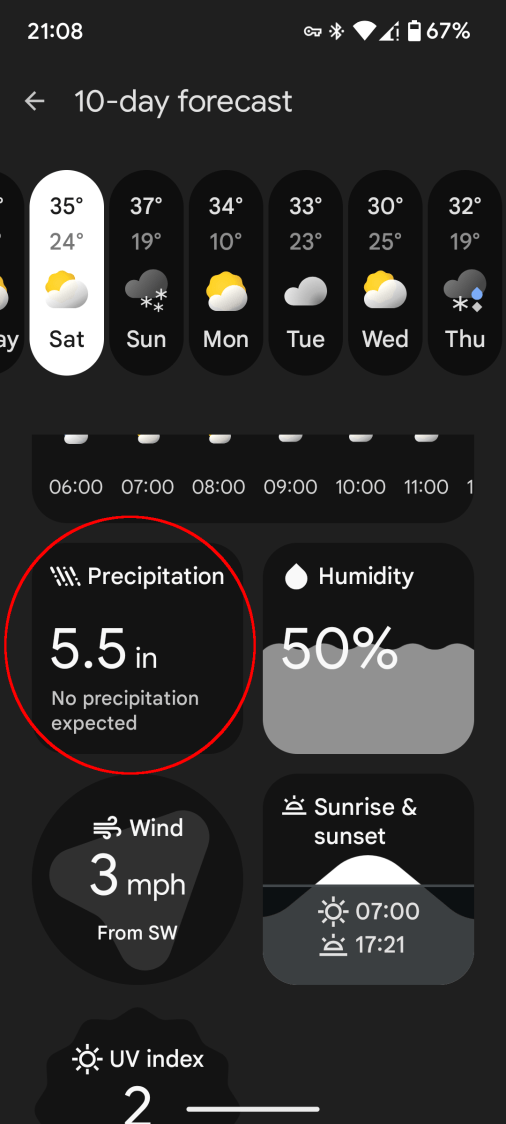
We didn’t get half a foot of any precipitation that day.
That is apparently the “Pixel At a Glance” app using info scraped from weather-dot-com. The other Google Weather app, the one that may or may not still have the Weather Frog, scrapes info from noaa-dot-gov and seems somewhat less uncoordinated.
The two apps generally disagree on what kind and how much precipitation will occur, sometimes absurdly, and rarely agree with the official National Weather Service forecast.
Sometimes the forecasts have not converged by the time the weather arrives outside the window.
Trying out the Track Lock Blocks brought a long-standing puzzle to the surface: the left front wheel rode about a millimeter above its track, with the other three wheels carrying the weight of the machine. Neither that wheel nor the diagonally opposite wheel on the right rear worked well with the Blocks, because the machine rocked on the other two wheels.
I initially thought the carriage rail under the machine was warped, but some poking and prodding showed the left front wheel rode higher than the others from front to back across the entire length of the table.
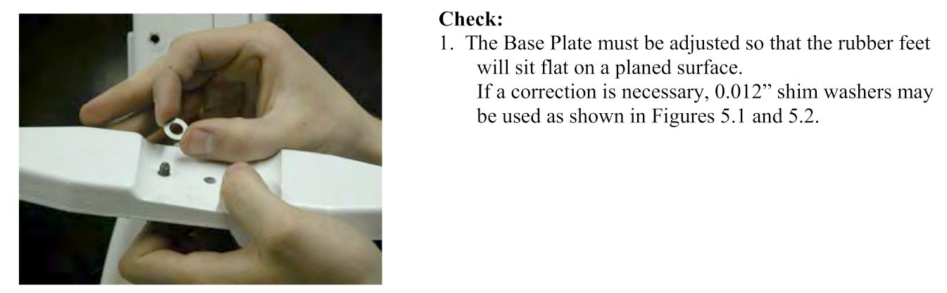
So I loosened the screws holding the front wheel base plate to the machine and jacked up the front of the machine to get the wheels off their tracks:
HQ Sixteen – track lock – jacking machine
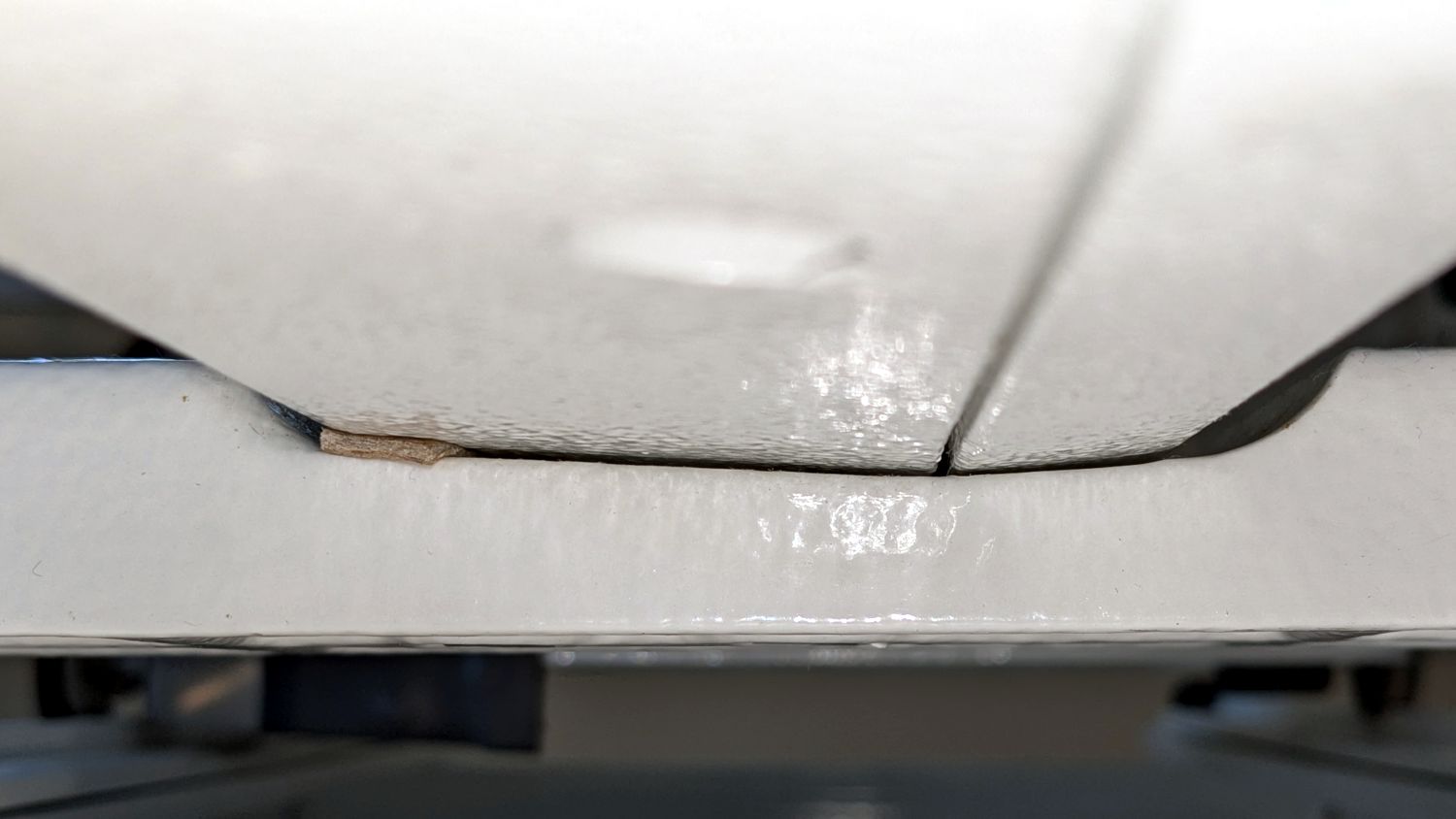
Then I jammed two strips of chipboard into the left side of the gap:
HQ Sixteen – front wheel base plate shim
I planned to use one long strip across the entire wheel base plate, but the screw holding the machine casting to the plate blocks the way, so it now has two shorter strips. Tightening the screws clamped the chipboard in place.
The chipboard tilted the base plate and lowered the left wheel, with the right wheel surely moving slightly upward. Lowering the machine showed both front wheels now carry roughly the same load and the Track Lock Blocks now work the way I expected.
The only “planed surface” around here is on the surface plate in the Basement Shop, two flights of stairs away, and I am not carrying either object to meet the other.
In any event, I think the chipboard serves the same purpose as a simple washer, with advantage of a much larger bearing surface, so I’ll call it Good Enough until something else causes me to take the wheel base plate off.
Mary’s practice quilts on the HQ Sixteen suggest locking the machine’s wheels will simplify sewing a line parallel to the long edge of a quilt parallel to the table, but contemporary “Channel Locks” fit newer machines with larger wheels than on this one.
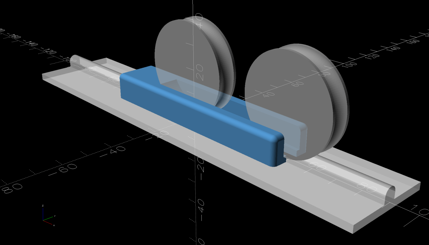
Duplicating those rings in a smaller size seemed both difficult and not obviously functional, so I built a pair of blocks to capture the wheel on its track:
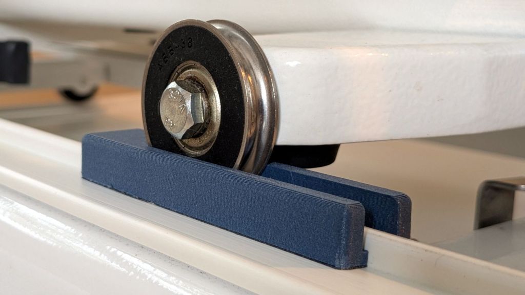
HQ Sixteen – track lock – engaged
The wheel sits in a recess holding it just barely above the track surface, so the (considerable) weight of the machine holds the block in place.
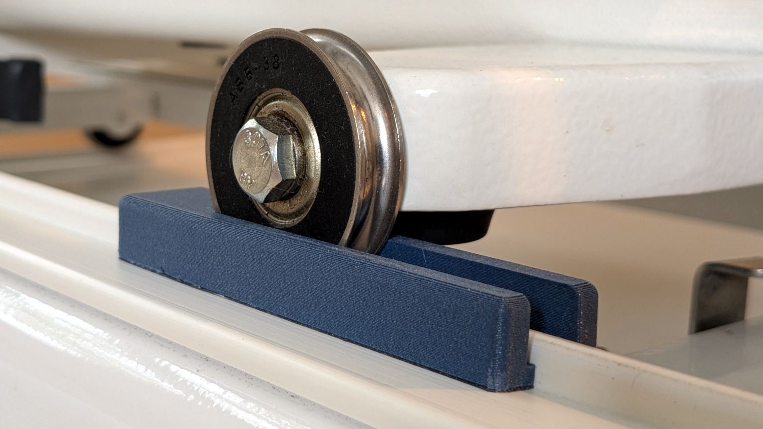
Because lines on quilts have precise placement and Mary has quilting rulers within reach, the block measures exactly two inches from the point where it first touches the wheel to the center of the recess:
HQ Sixteen – track lock – setup
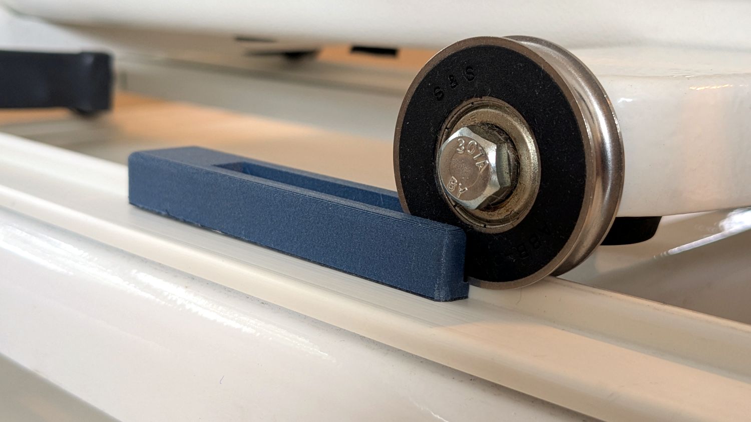
She can then lay a ruler on the quilt, roll the machine front or back two inches, slide a block against each wheel, then roll the machine up a slight incline until the wheel drops into the recess:
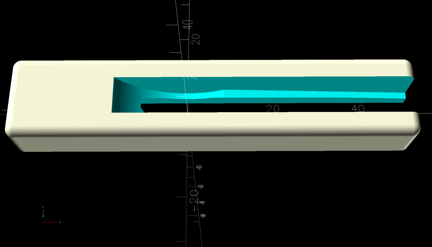
HQ Sixteen – track lock block – solid model
The spacing looks like this:
HQ Sixteen – track lock block – solid model – show view
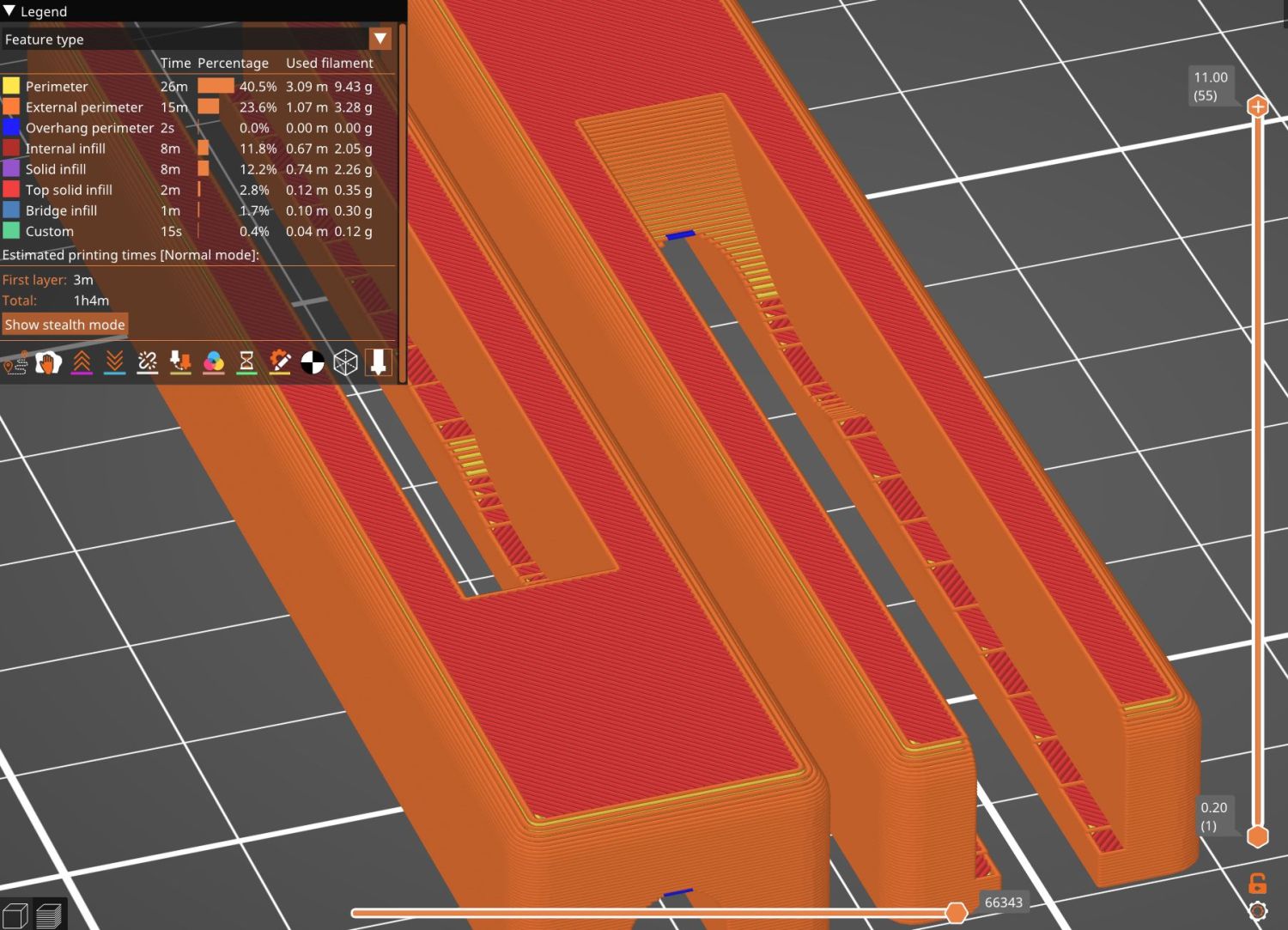
The usual 3D printing process puts 0.2 mm steps along the ramp, but they’re almost imperceptible while rolling the machine:
The ramp slope is all of 1:20 = 2.5°, so pulling / pushing the machine requires very little oomph.
I put thin cloth tape (approximately friction tape, but with real adhesive) on the bottom of the block by the simple expedient of sticking it to the block and scissoring off the excess. A little compliance between the block and the track prevents the hard plastic shapes from sliding more easily than I’d like. If your tape is thicker than mine, knock a little off the WheelZ value.
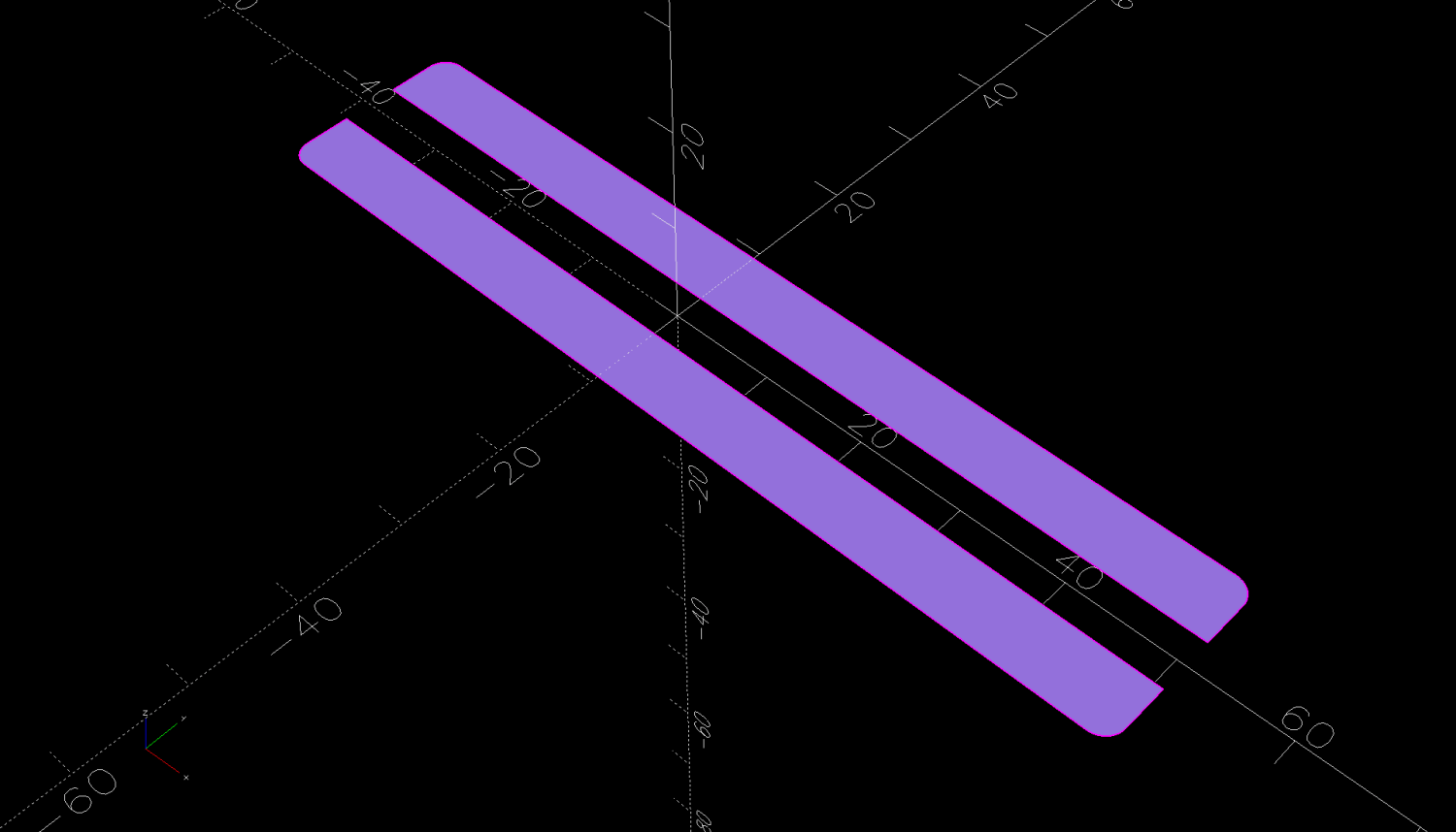
The OpenSCAD code can produce shapes to laser-cut an adhesive sheet, although stacking a foam sheet will definitely require height adjustment :
This file contains hidden or bidirectional Unicode text that may be interpreted or compiled differently than what appears below. To review, open the file in an editor that reveals hidden Unicode characters.
Learn more about bidirectional Unicode characters
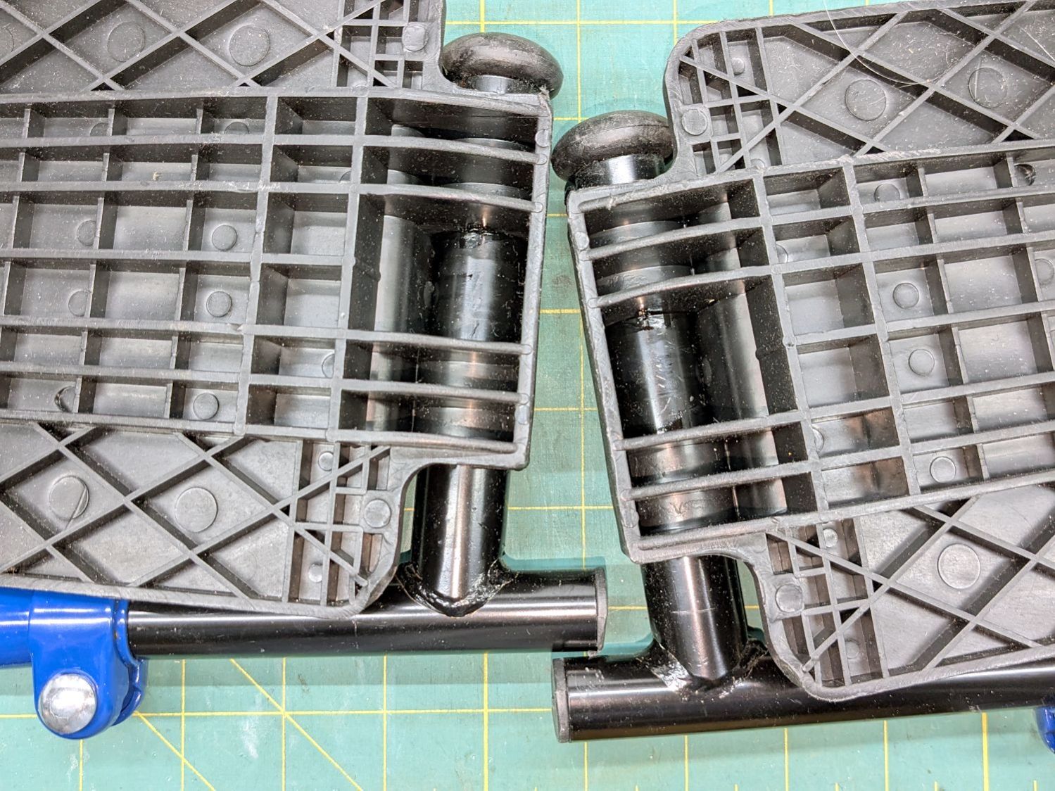
After few days in the Drive Blue Streak wheelchair, I finally lubricated the foot rest pivots:
Drive wheelchair foot rest lubrication
The complex molded rests gripped their metal tubes so tightly as be nearly immovable, but one drop of Kroil at the four obvious spots let them turn much more easily.
The flange overlapping the upright tube along the bottom of the picture hits the short protrusion and holds the rest parallel to the floor. A screw at the plastic cap near the top keeps the rests from working their way too far from the upright tube.
I can make it to the Basement Shop™ and back, paying careful attention to detail.
Mary wanted a Ruler Foot (a.k.a. Handi Feet Sure Foot) on her Handi Quilter HQ Sixteen sewing machine, which required removing the original foot, installing the Handi Feet Conversion Kit, then adjusting the foot height above the needle plate:
The Conversion Kit instructions repeatedly recommend hauling the machine to your local Handi Quilter authorized dealer / repair center, which would be an hour’s drive away. Suffice it to say I’m both authorized by a suitable authority and a dab hand with a hex wrench: I can do this thing.
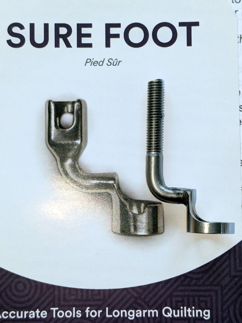
The original foot is a welded assembly with an M5×0.8 screw thread matching the leftmost (darker) rod on the machine:
HQ Sixteen Handi-feet conversion – original foot
It’s sitting atop the label of the Sure Foot kit with a picture of the ruler foot.
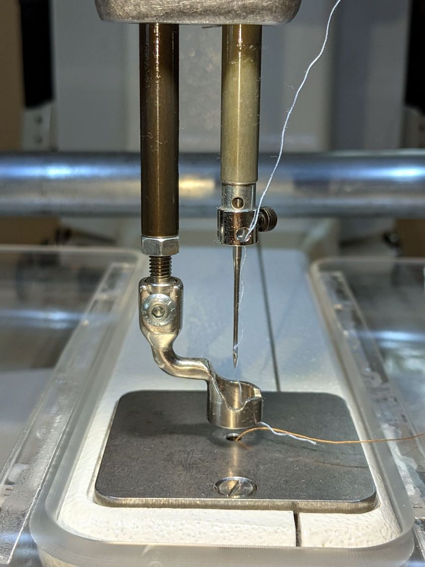
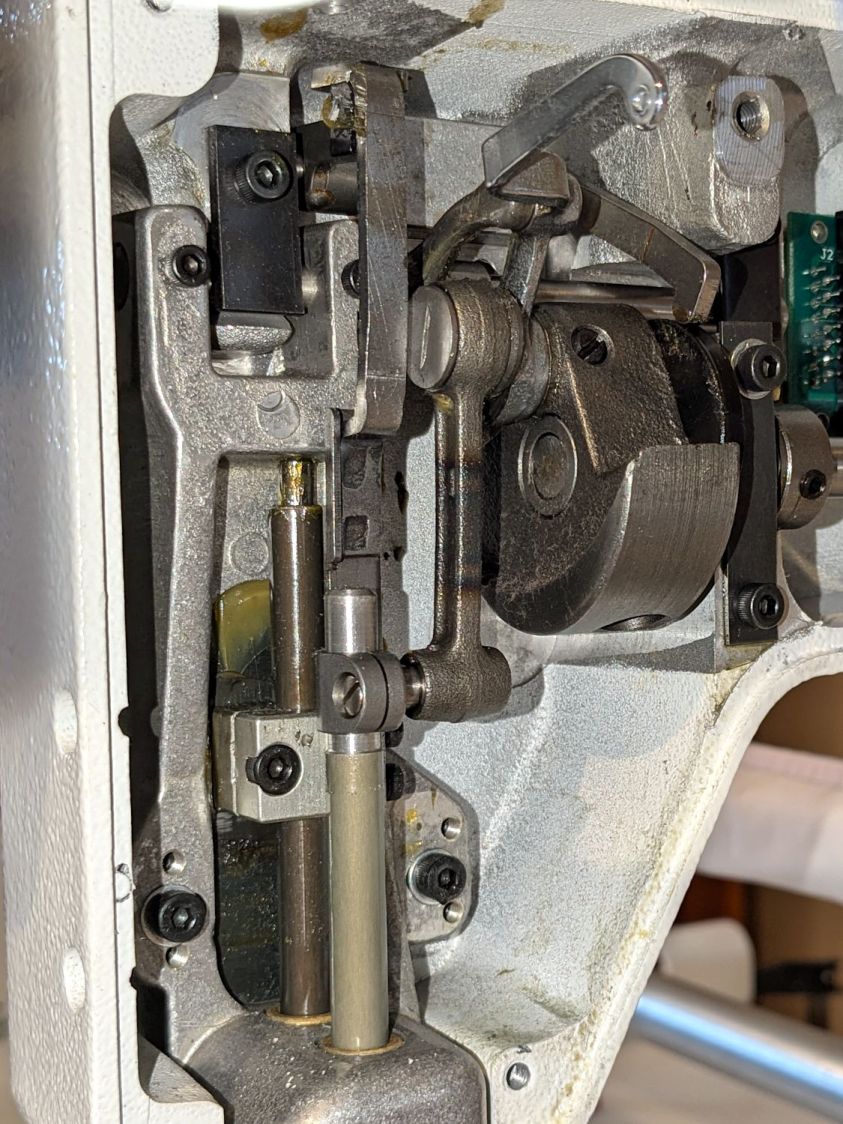
Although the instructions suggest you can install the conversion kit without removing the machine cover, I wanted to see what was going on in there and verify everything fit properly:
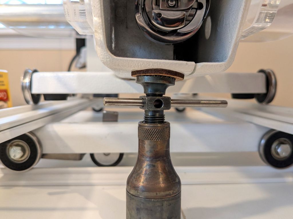
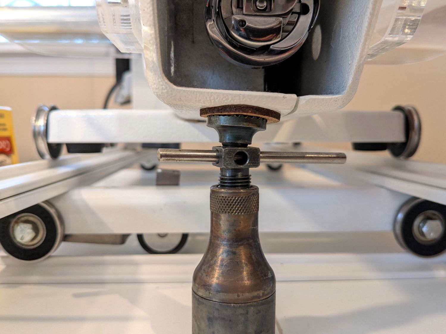
HQ Sixteen Handi-feet conversion – foot rod clamp
As above, the foot / adapter screws into the left rod, with the rectangular aluminum clamp attached to the follower riding the cam near the top of the machine. The rod slides on the greasy pin absorbing the torque from the follower.
I had to loosen the clamp, slide the rod upward, unscrew the original foot, install the adapter, adjust the rod position for the proper 0.5 mm spacing between ruler foot and the needle plate at bottom dead center, then tighten the screw. The disturbed grease above the block reveals I moved the rod upward about 8 mm through that block during the process; it now sits lower, just a few millimeters above where the factory tech assembled it for the original foot.
The top photo shows half a dozen threads between the top of the adapter and the bottom of the jam nut. Without adjusting the rod position in the clamp, the adapter screw threads are the only way to adjust the foot-to-plate space: each full turn moves the foot 0.8 mm. I screwed the adapter completely into the rod, then backed it out three turns to leave enough adjustment for other feet and fabrics.
The machine cover has a hole providing access to the clamp screw, so, in principle, you can stick a hex wrench in there to loosen / tighten the clamp while making fine adjustments in the foot position, all without removing the cover. If one full turn of the adapter doesn’t set the right position, I highly recommend removing the machine cover to see what you’re doing.
We then installed the Ruler Base on the machine, which required removing the preinstalled Medium fuzzy spacer strips, and all’s well that ends well.
Over the past year, the ancient WordPress theme I use for this blog has gradually stopped working, to the extent that some of you cannot enter comments and the GitHub Gists no longer display properly.