Ed Nisley's Blog: Shop notes, electronics, firmware, machinery, 3D printing, laser cuttery, and curiosities. Contents: 100% human thinking, 0% AI slop.
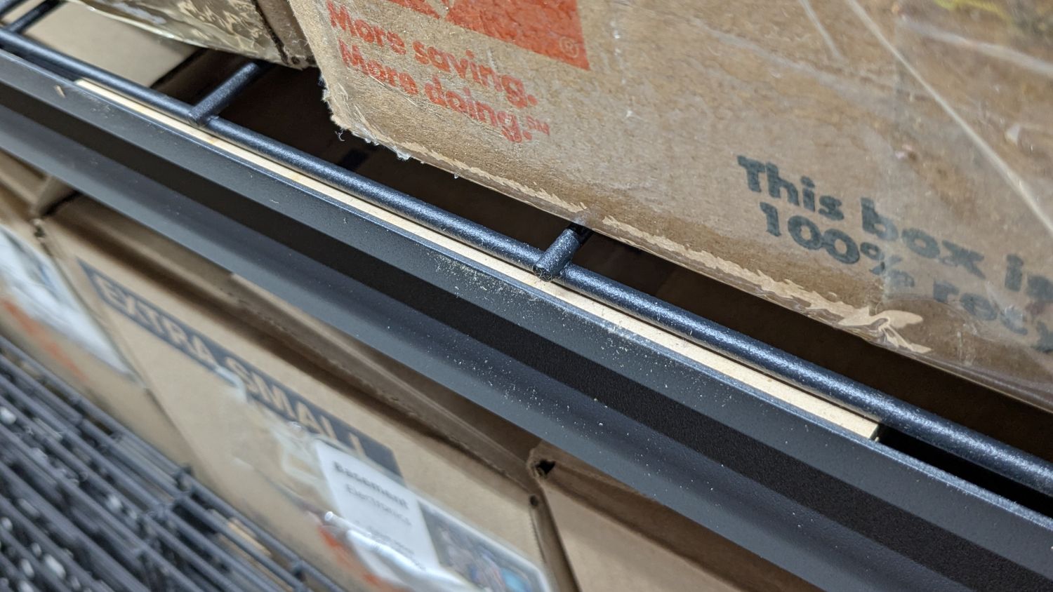
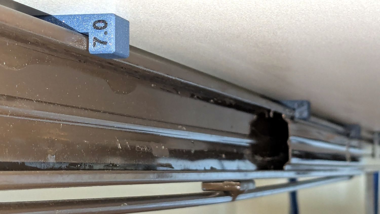
I’m finallyassembling the shelves for the last of the boxes cluttering the basement floor. Because the top of the wire shelf grid sits 4 mm below the top of the shelf rails, surely for some good reason, that pale strip is a 6 mm shim raising the grid just enough to let the boxes slide easily off without having to lift them over the rail.
It’s a pair of 3 mm thick MDF strips stuck together with tapeless sticky (a thin adhesive layer on backing paper), with the same adhesive holding the shim to the rail while I lay them down and plunk the shelf grid on top:
Wire Shelf Shim – side view
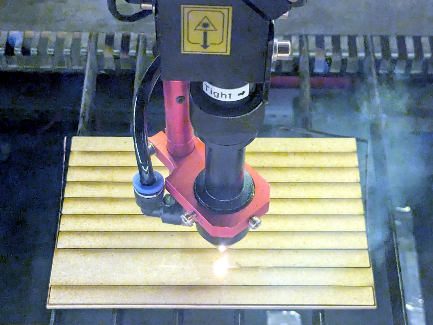
I made two sets of shims to fit the support rod spacing, with lengths carefully chosen to match two stacks from my Big Box o’ MDF Cutoffs, all 10 mm wide to fit the shelf rails:
Wire Shelf Shim – laser cutting
Admittedly, not all of the neatly rounded corners came through, due to slight variations in MDF sizing / Print-and-Cut alignment / whatever, but it’s a nearly zero waste way to turn stock into strips.
Each shelf needs 14 shims = 28 strips and I’m here to tell you if I had to bandsaw 140 little strips for each of three sets of shelves, well, I:
Probably wouldn’t ever get around to making them
Definitely would grumble about lifting those boxes, forever
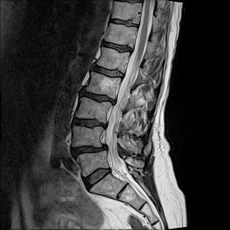
The L4-L5 pair are part of an extensive human anatomic model locating all the pieces at their proper coordinates, so these two hovered about 800 mm above the XY plane. I ran them through the Grid:Tool mesh editor to center them at the XY origin, then put the bottom-most point at Z=0.
Rotating them individually in PrusaSlicer and painting only the most essential support got them to this state:
L4 L5 vertebrae – PrusaSlicer
Each one take about three hours, so I ran them individually to reduce surface blemishes and maximize the likelihood of happy outcomes. Worked like a champ.
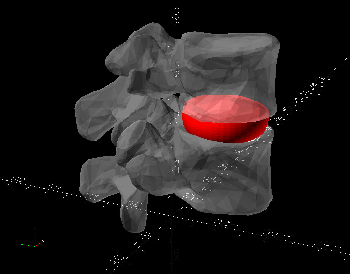
The retina-burn orange disk is not anatomically correct, because the InterWebz apparently does not have a model for spinal cartilage:
L4 L5 vertebrae – assembled – disk detail
Instead, it’s a rounded cylinder resized into an oval, with its top and bottom surfaces formed by subtracting the vertebrae:
L4 L5 vertebrae disk – solid model
The OpenSCAD code doing the heavy lifting:
// Disk between L4 and L5 vertebrae
// Ed Nisley - KE4ZNU
// 2025-03-07

Layout = "Show";    // [Show,Build]

include <BOSL2/std.scad>

module Disk() {
  color("Red")
    difference() {
      translate([9,-18,36])
        rotate(110)
        resize([33,45])
        cyl(d=50,h=14,$fn=48,rounding=7,anchor=BOTTOM);
      import("../Spine/human-spinal-column-including-cervical-thoracic-and-lumbar-vertebra-model_files/L4 L5 vertebrae stacked.stl",
        convexity=10);
    }
}

if (Layout == "Show") {
  Disk();

  color("White",0.3)
      import("../Spine/human-spinal-column-including-cervical-thoracic-and-lumbar-vertebra-model_files/L4 L5 vertebrae stacked.stl",
        convexity=10);

}

if (Layout == "Build") {
  Disk();

}
All of the magic numbers come from eyeballometric measurement & successive approximation.
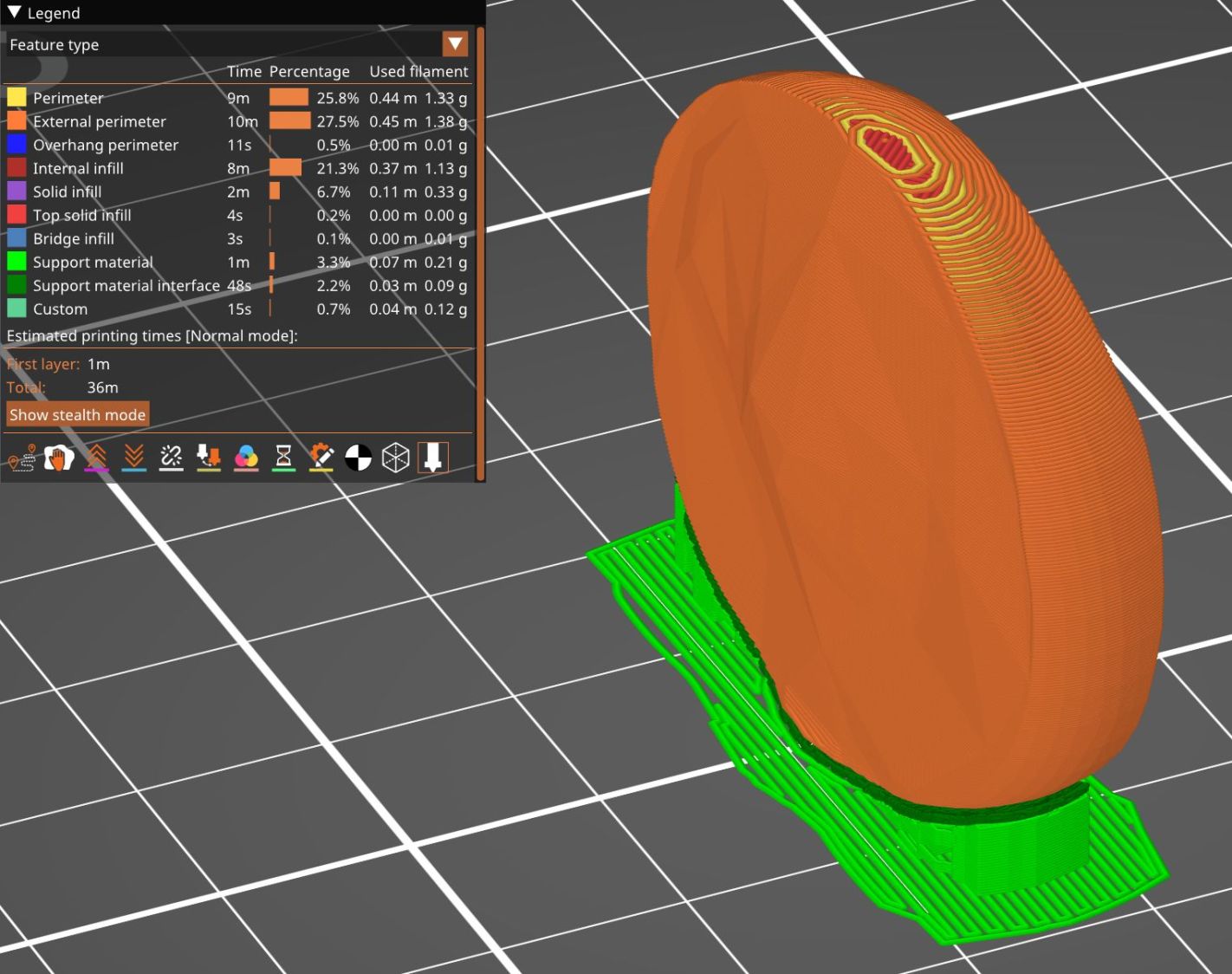
The Build layout left the disk floating in space, whereupon I used PrusaSlicer to reorient it edge-downward on the platform with painted-on support for minimal distortion:
L4 L5 vertebrae disk – PrusaSlicer
Two dots of E6000+ adhesive hold everything together.
All in all, it was a useful distraction. I’ve been vertically polarized for the last five days and it’s good to be … back.
Having devoted considerable effort to smoothing the HQ Sixteen’s path across the table, with commensurate improvement, Mary reported the machine suddenly developed a severe hitch in its left-to-right git-along. Given that she is moving fifty pounds of machine with fingertip pressure, anything interrupting its progress is a problem.
We found a spot where the machine abruptly and repeatably stopped rolling, but none of the four wheels had a visible problem and both tracks were smooth. The stitch regulator wheel sat directly above a table surface joint on the track base, but lifting it didn’t change the glitch. Rolling the machine while lifting the rear wheels off the track, which is significantly more difficult than it may seem, still encountered the bump.
Rolling while lifting the front wheels went smoothly, so something was wrong with one of the front wheels. I put the machine back at the worst spot, marked the bottom of both wheel rims, lifted-and-rotated the left wheel half a turn, and found the glitch happened with the right wheel’s mark downward.
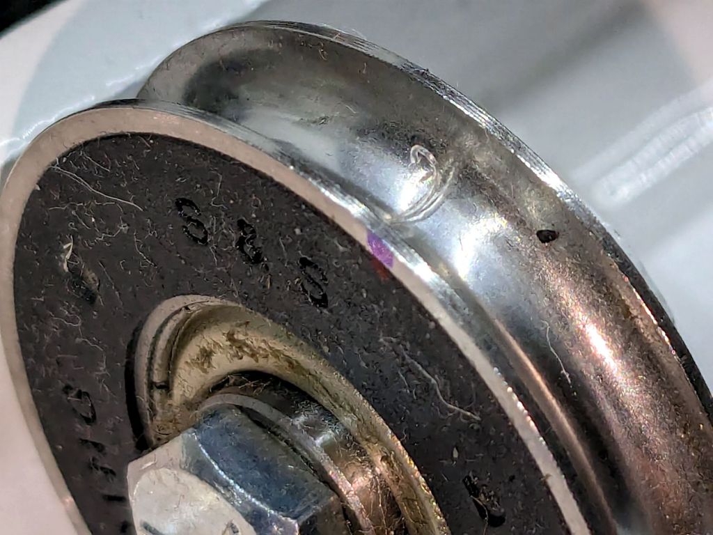
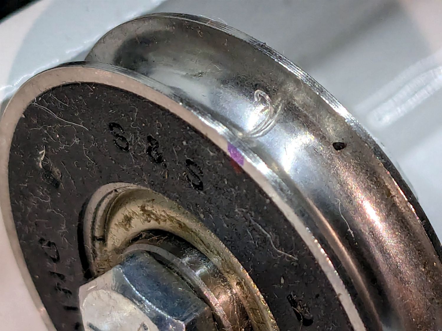
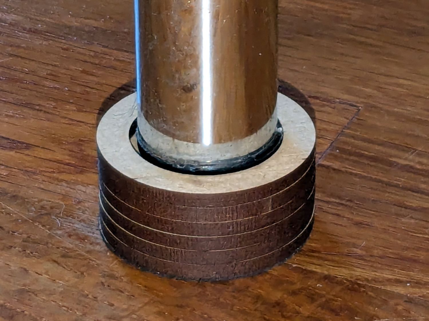
I lifted the machine off the carriage, took the carriage to the Basement Shop, and discovered what we could not see in situ:
HQ Sixteen – wheel crud – detail
For scale, the wheels are 8 mm across the flanges.
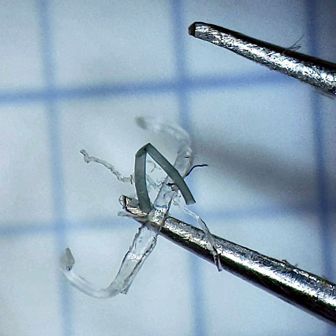
That thing looks like this up close:
HQ Sixteen – wheel crud – detail
The fibers were almost invisible in my palm as I carried it upstairs to show it off.
Apparently, a few millimeters of plastic fiber dropped from space directly onto the track and got mashed into the wheel as it rolled along. Given the vast expanses of fabric & batting going into projects on a long-arm sewing machine, that crud could have come from anywhere.
As we now realize just how much trouble can come from a tiny bit of crud, finding the next hitch in the git-along will be easier.
Although the images are algorithmically generated in a common layout, figuring out how to get the outlines as paths seemed to require a journey into the depths of the Pygame library and that would turn into a major digression.
Instead, start with one of the webp images:
sq_RGBY
The deliberate blurring apparently simulates what you see in real life.
Import the image into LightBurn, which converts it to grayscale under the plausible assumption you’re going to engrave the image on something. Then:
Create a rounded rectangle overlaying the lower-left-most subpixel to good eyeballometric accuracy
Turn it into a four-element rectangular array, twiddling the center-to-center spacing to match the subpixel layout
Duplicate those four upward in another array to create a subpixel block, as marked in the upper-left corner of the original image
Slam another array across the bottom row and upward, twiddling the spacing to match the subpixel block spacing along both axes
Which eventually looks like this:
SubPixels – LightBurn vector overlay
I made the final array absurdly large, cropped it with a square to match the template I used for the layered paper patterns, resized the result to be 170 mm on a side, then dropped the square into the middle of the template:
Subpixel Zoo – Quattron RGBY – LightBurn black mask layer
One gotcha: crop the subpixels on a Fill layer so LightBurn will close the truncated edges, then put them on a Line layer for cutting. The doc explains why, although it’s not obvious at first, as is the fact that you must delete the group of shapes outside the square before it looks like anything happened during the cut operation.
The resulting layout contains all the subpixel rectangles, so it’s what you want for the top black mask layer. Duplicate the pattern and delete the subpixels corresponding to each color, until you have one template for each of the Red / Green / Blue layers:
Subpixel Zoo – Quattron RGBY – LightBurn layers
The blank over on the right is the Yellow layer, which does get a quartet of layer ID holes cut in the lower right corner.
Then it’s just a matter of cutting the blanks, locating the fixture on the platform, dropping the appropriate color sheet in place, cutting it, then assembling the stack in the gluing fixture:
Subpixel Zoo – Quattron RGBY
It’s kinda cute, in a techie way.
I did a bunch of layouts, just to see what they looked like:
Subpixel Zoo – 8×8 layouts
In person, the RGBY patterns look bright and the RGB patterns seem dull by comparison. I’m using cardstock paper, rather than fancy art paper, which surely makes all the difference.
Both of those “projects”, which may be too grand a term, went from “I need a thing” to having one in hand over the course of a few minutes yesterday. Neither required a great deal of thought, having previously worked out the proper speed / power settings to cut 3 mm MDF and 1 mm cork.
Other folks may lead you to believe lasers are all about fancy artwork and elaborate finished products. Being the type of guy who mostly fixes things, I’d say lasers are all about making small and generally simple parts, when and where they’re needed, to solve a problem nobody else has.
Perhaps I should devote more attention to using fancy wood with a hand-rubbed wax finish, but MDF fills my simple needs.
With a laser and a 3D printer, shop tools have definitely improved since the Bad Old Days!
I asked for the images from recent X-ray and MRI sessions, whereupon a CD arrived in the mail. Popping it into my desktop Linux box produced this directory listing:
ll /run/media/ed/Feb\ 21\ 2025/
total 146M
dr-xr-xr-x  2 ed   ed    136 Feb 21 13:14 ./
drwxr-x---+ 3 root root   60 Mar  2 13:40 ../
-r--r--r--  1 ed   ed   146M Feb 21 13:14 -NISLEY-DMBG8yMQcf8qXcVj.iso
It seems whoever / whatever produced the CD copied the ISO image to the CD, rather than burning the ISO directly to the CD. As a result, the CD has one file.
Raise your hand if you’ve never done that.
Well, I was going to save the CD as an ISO file anyway, so I just copied it to the file server.
Attempting to mount it produces an odd result:
sudo mount -o loop "-NISLEY-DMBG8yMQcf8qXcVj.iso" /mnt/loop/
[sudo] password for ed: <make up your own>
mount: failed to set target namespace to ISLEY-DMBG8yMQcf8qXcVj.iso: No such file or directory
Oh, right, starting a filename with a leading dash is never a Good Idea™.
Rename it:
mv -NISLEY-DMBG8yMQcf8qXcVj.iso NISLEY-DMBG8yMQcf8qXcVj.iso
mv: invalid option -- 'N'
Try 'mv --help' for more information.
The Handi-Quilter HQ Sixteen rides on two tracks along the 11 foot length of the table, with an unsupported 8 foot span between the legs on each end:
HQ Sixteen – remounted handlebars in use
Contemporary versions of the table have support struts in the middle that our OG version lacks and, as a result, our table had a distinct sag in the middle. During the course of aligning the table top into a plane surface with tapered wood shims, I discovered the floor was half an inch out of level between the table legs.
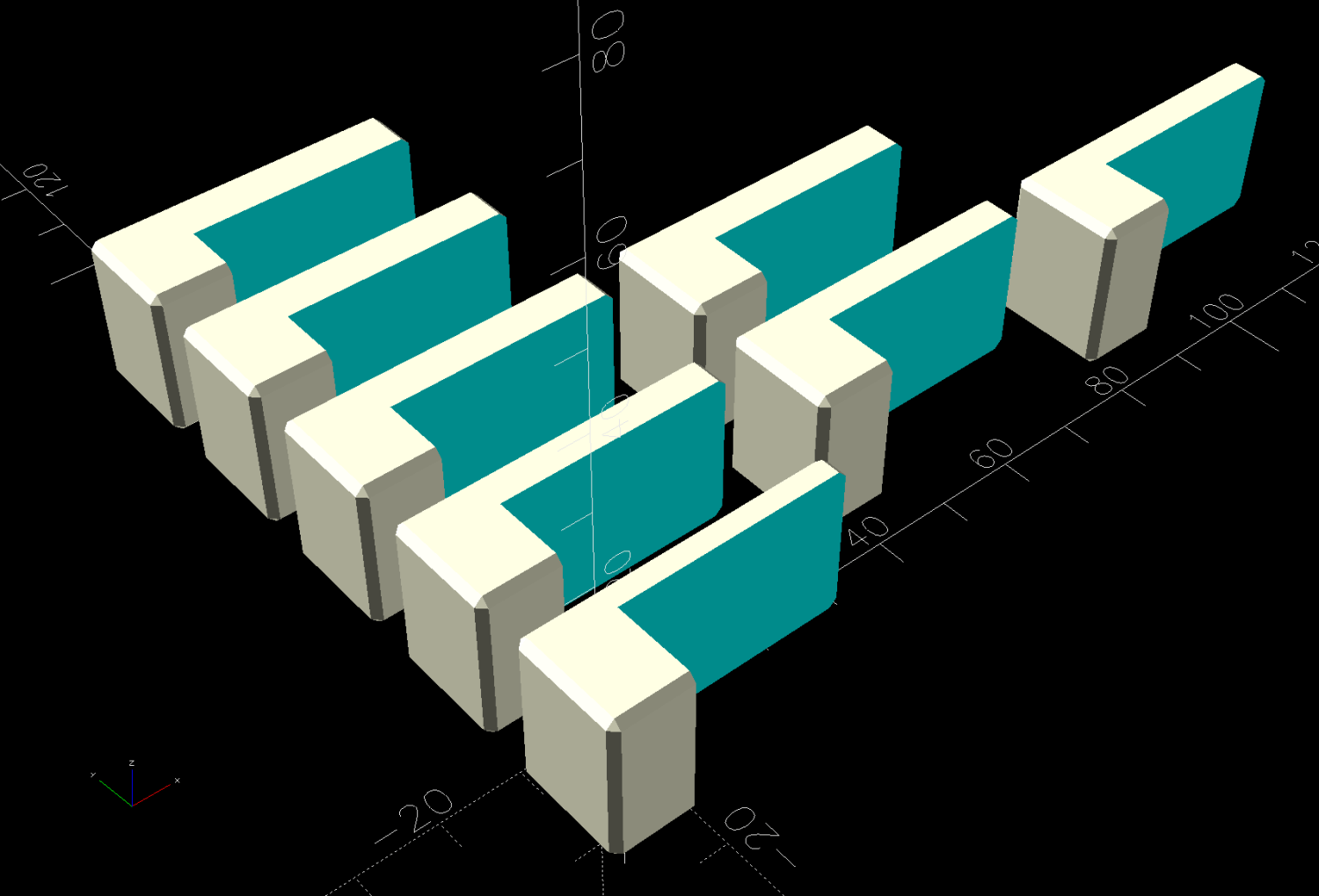
Now that the whole thing has settled into place, I measured the shim thicknesses and made tidy blocks to replace them:
HQ Sixteen – table shims – finished
The OpenSCAD code has an array with the thickness and the number of blocks:
Yes, I call them “blocks” here and wrote “shims” in the code. A foolish consistency, etc.
The model is a chamfered block with a chunk removed to leave a tongue of the appropriate thickness:
HQ Sixteen – table shims – solid model
Building them with the label against the platform produces a nice nubbly surface:
HQ Sixteen – table shims – PrusaSlicer – bottom
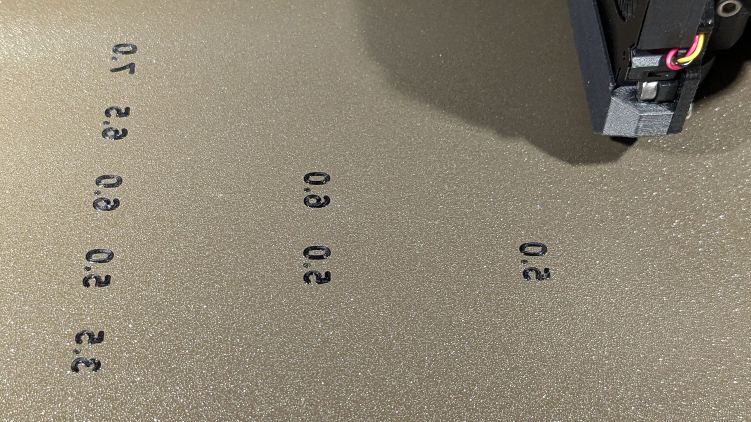
The labels print first and look lonely out there by themselves:
HQ Sixteen – table shims – legends
The rest of the first layer fills in around the labels:
HQ Sixteen – table shims – first layer
Putting the labels on the bottom makes the wipe tower only two layers tall and eliminates filament changes above those layers. Those eight blocks still took a little over three hours, because there’s a lot of perimeter wrapped around not much interior.
Having had the foresight to draw a sketch showing where each block would go, I slid one next to its wood shim, yanked the shim out, and declared victory:
HQ Sixteen – table shims – installed
The tension rod welded under the table rail prevents even more sag, but the struts under the new version of the table show other folks were unhappy with the sag of this one. Another leg or two seems appropriate.
With the table leveled and the surface aligned, the HQ Sixteen glides easily in all directions. The result isn’t perfect and Mary keeps the anchor block at hand, but the machine now displays much less enthusiasm for rolling toward the middle of the table.
The OpenSCAD source code as a GitHub Gist:
This file contains hidden or bidirectional Unicode text that may be interpreted or compiled differently than what appears below. To review, open the file in an editor that reveals hidden Unicode characters.
Learn more about bidirectional Unicode characters