Ed Nisley's Blog: Shop notes, electronics, firmware, machinery, 3D printing, laser cuttery, and curiosities. Contents: 100% human thinking, 0% AI slop.
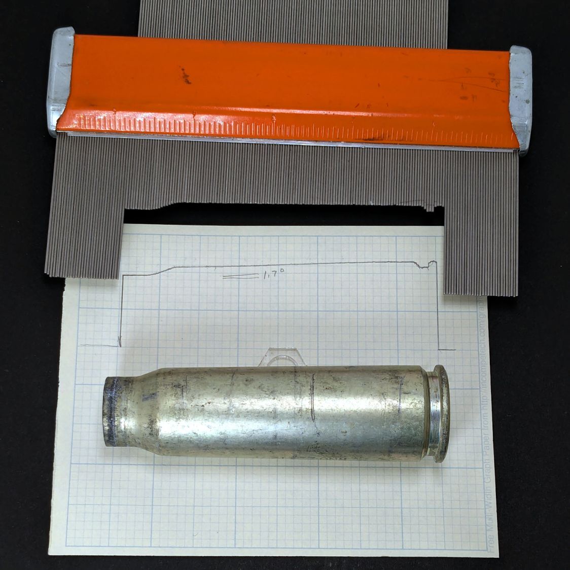
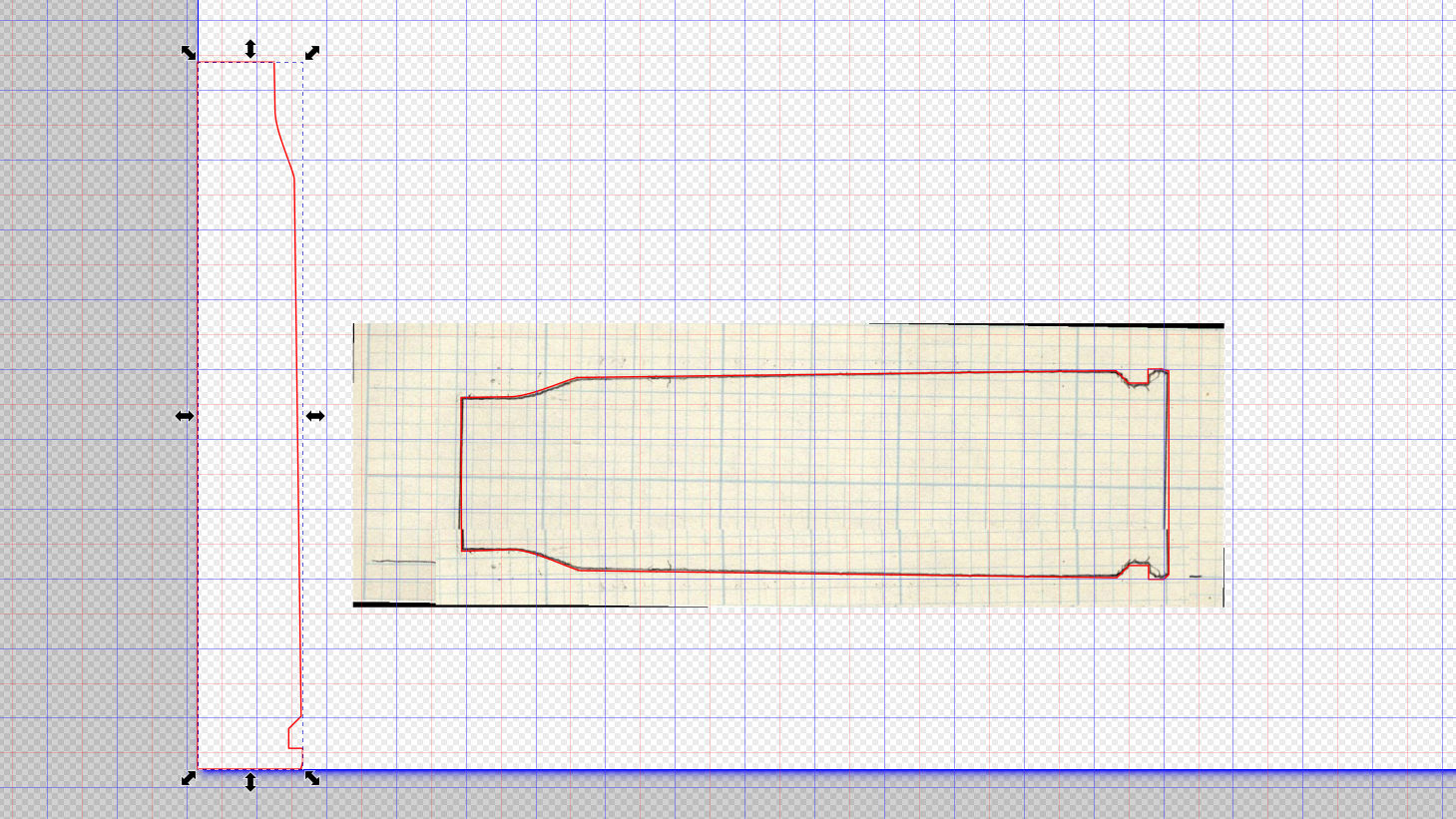
Scan the sketch, import into Inkscape, rotate the image to correct the case taper angle vs. the page, lay lines & curves around the perimeter, align half of it at the page origin to work with OpenSCAD, export as SVG:
Cartridge – 20x102mm outline – Inkscape layout
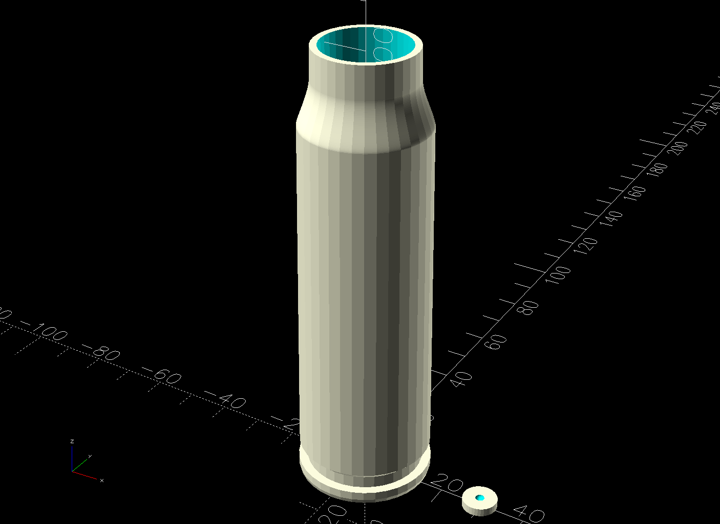
Import into OpenSCAD, let rotate_extrude do the heavy lifting, and remove some pieces:
Cartridge Case – build view solid model
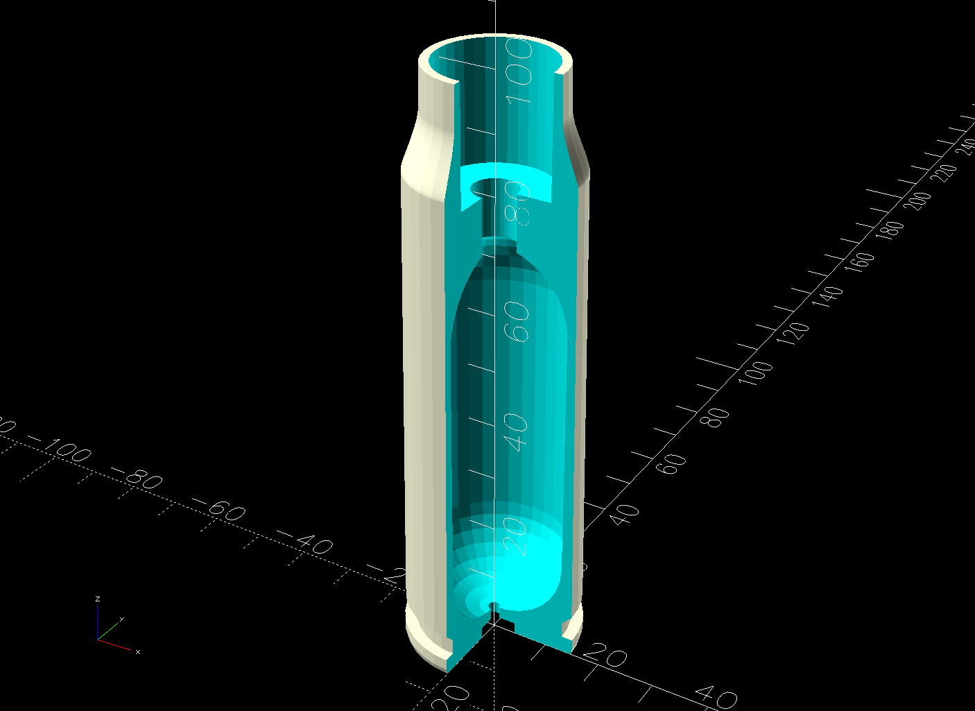
The little disk represents a fired primer you’d print separately in a different color and glue into the pocket shown in this cutaway view:
Cartridge Case – cutaway solid model
The interior void could hold sand for additional heft, as the whole thing is obviously nose-heavy; that’s certainly in the nature of fine tuning. Obviously, we are not dealing with anything that could go bang.
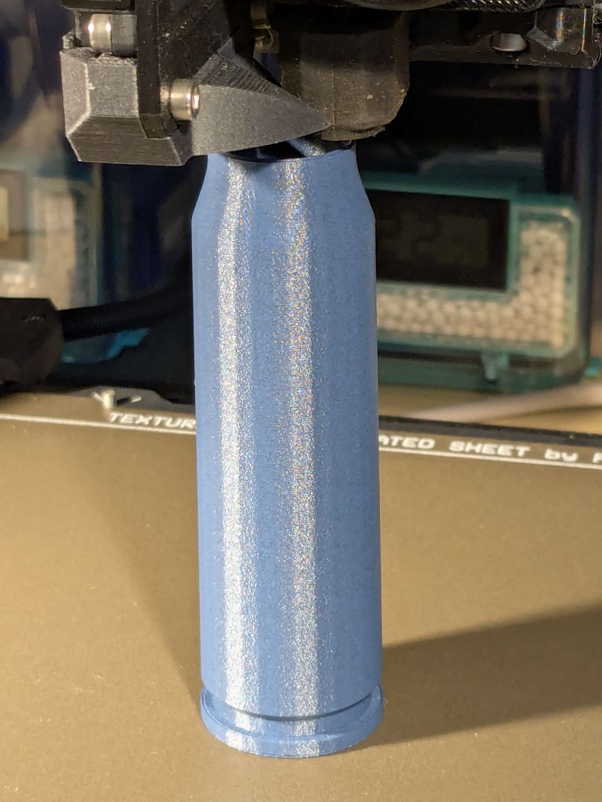
It builds just like you’d expect:
20x102mm cartridge – printing
Dab some adhesive on the capsule tip, ditto for the primer, stick them in place, and it’s all good.
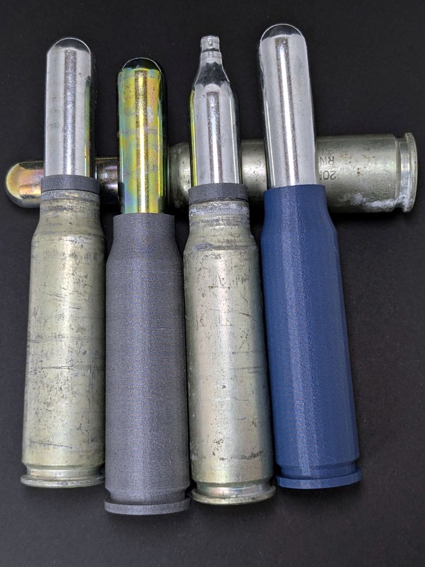
I like the gray PETG-CF version:
20x102mm cartridges – blue gray PETG-CF
Maybe not such a good idea in this day & age. Print responsibly, as they say.
Update
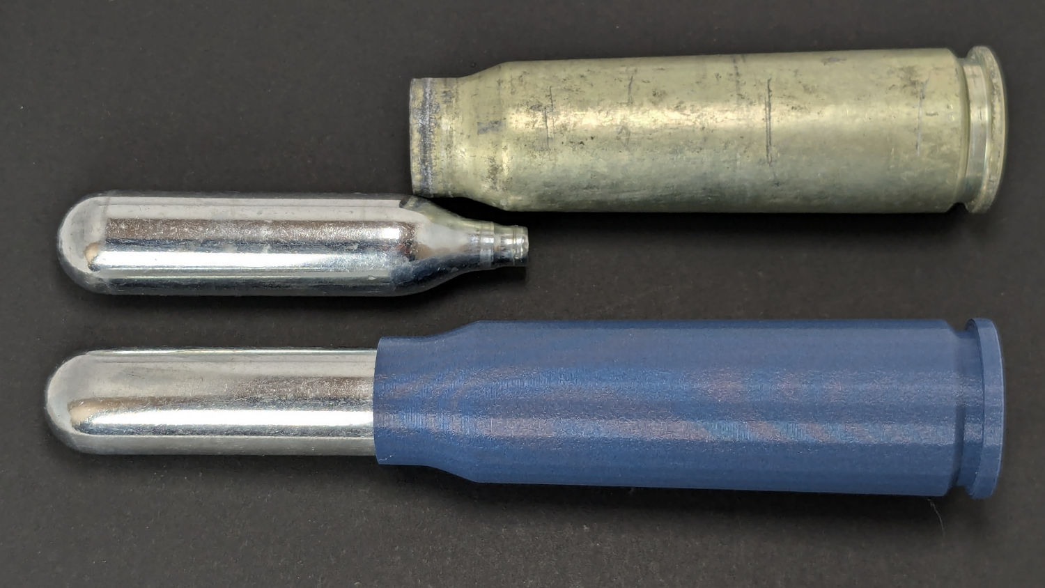
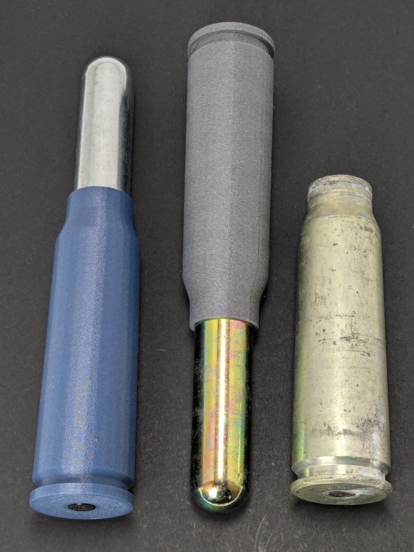
Print a sabot to fit a CO₂ capsule into a genuine steel cartridge.
This file contains hidden or bidirectional Unicode text that may be interpreted or compiled differently than what appears below. To review, open the file in an editor that reveals hidden Unicode characters.
Learn more about bidirectional Unicode characters
When our stick blender (Cusinart CSB-77, with an instruction manual dated 2011) failed, I dropped fifteen bucks on the shortest one we could find, which turned out to be inconveniently long for the shorter member of the user community. The old one recently emerged from the depths of the bench for triage; the failure was in the coupler between the motor and the blade shaft, but required complete disassembly before trying to repair it.
Pry out two obvious plastic plugs, remove two screws holding the top of the handle together, pull the handle apart, and reveal a PCB with a discrete diode bridge and an open-frame switch:
Stick blender coupler – PCB
Fortunately, the wire colors matched my preconception. Unsolder the wires to get that side of the handle off.
Un-bend the tab holding the metal shell to the plastic frame and pull it off, whereupon the frame halves unsnap to release the motor:
Stick blender coupler – shell removed
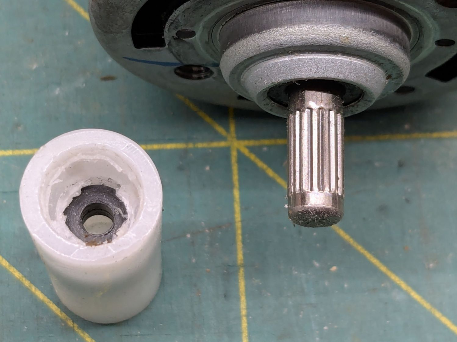
The white nylon (?) coupler on the motor shaft pries off the splined motor shaft:
Stick blender coupler – motor shaft splines
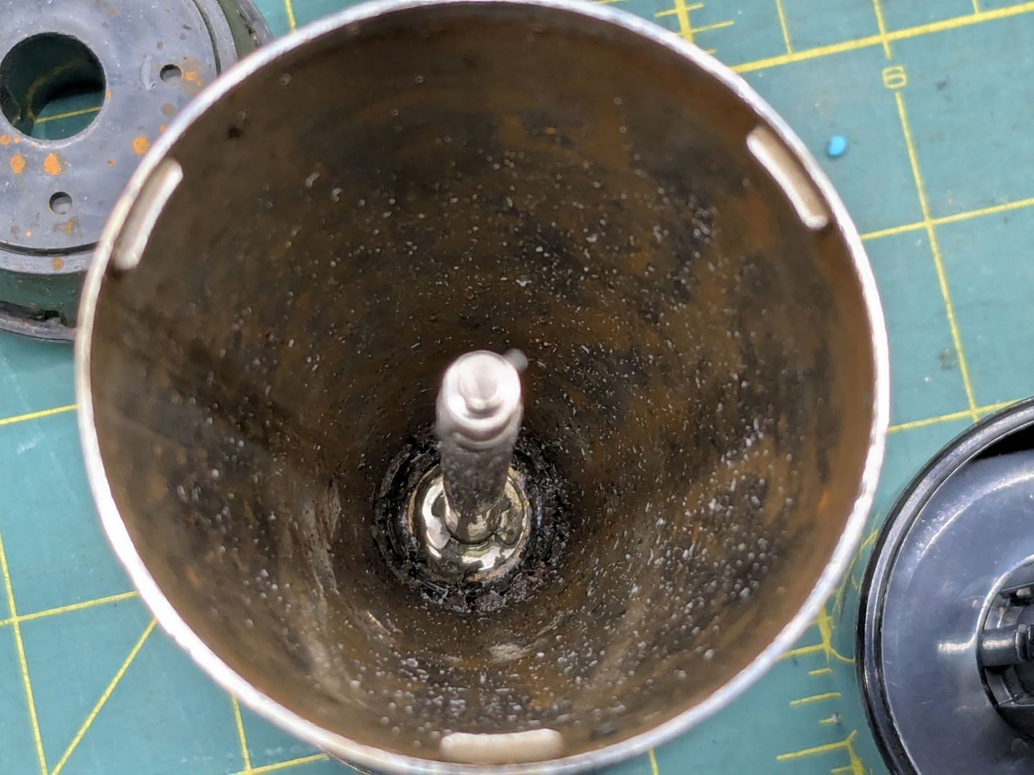
That black ring inside the coupler should be on the blade shaft:
Stick blender coupler – blade shaft
It apparently got jammed in the coupler when the shaft’s drive dogs / splines (barely visible down inside) ripped up the coupler. I don’t know if that was a sudden failure or the end result of gradually accumulating damage, but the inside of the coupler was badly chewed up.
Dismantling the blade unit requires prying three plastic clips back, one at a time, while pushing upward on the intricate black plastic fitting around the shaft:
Stick blender coupler – blade housing clips
That let me ease a drop of oil down the shaft to what looks and feels like a plastic sleeve bearing near the blade end of the housing; oil should not be needed on a plastic bearing, but it definitely improved the bearing’s attitude. The snap ring securing the shaft is far enough away to prevent me from even trying to remove it, because I know there is no way I can reinstall it:
Stick blender coupler – blade shaft snap ring
Some Xacto knife action removed the shredded plastic to reveal the remains of four slots for the blade shaft’s two drive dogs / splines:
Stick blender coupler – OEM coupler end view
Measuring All. The. Things. produced a reasonable solid model of the slots:
Stick Blender drive coupler – splines – solid model
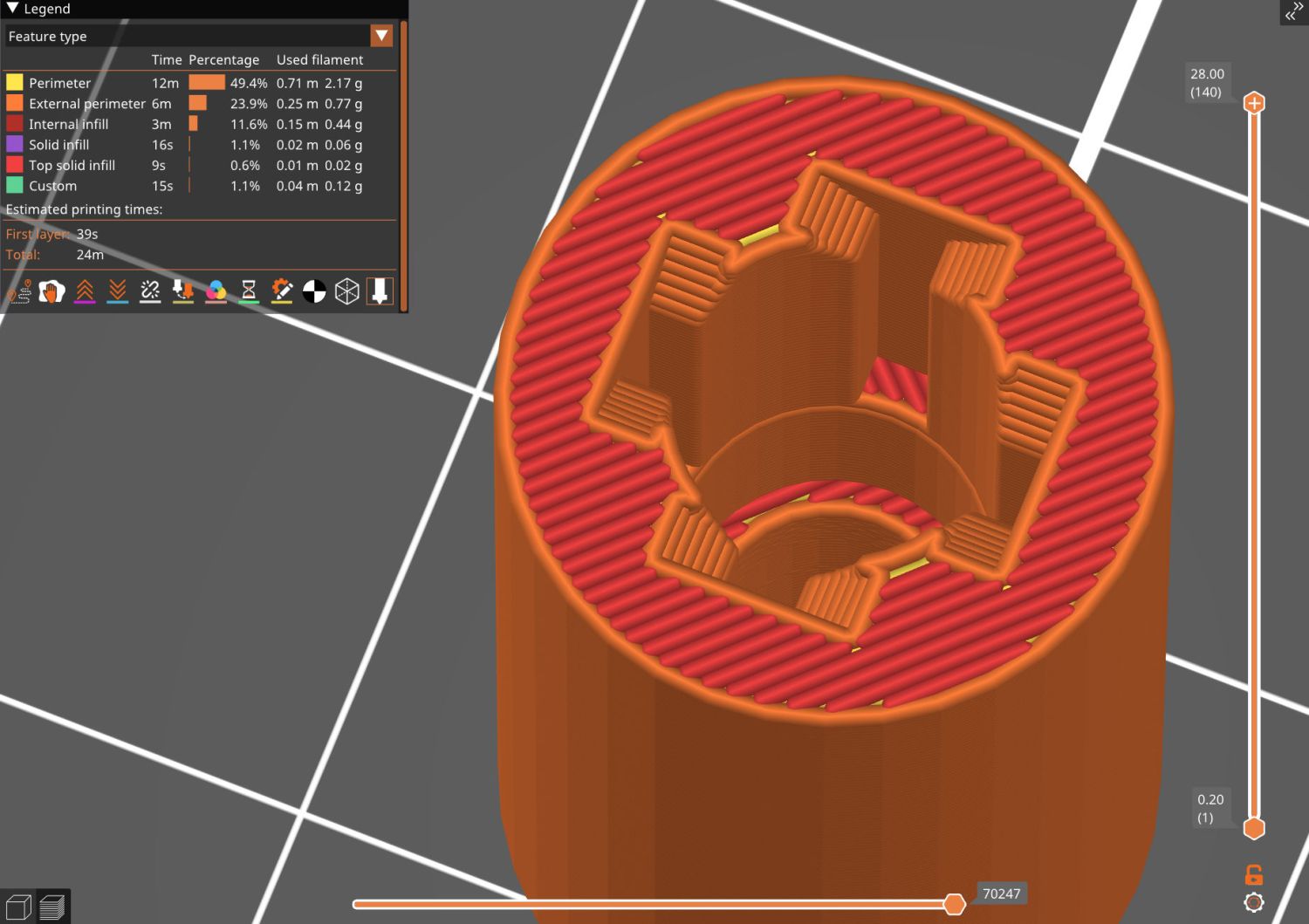
Removing those from a model of the coupler defined the shape:
Stick Blender drive coupler – PrusaSlicer
As usual, having one in hand let me check the fit and, after a few tweaks, the next one was Just Right™.
The other end of the coupler is a simple cylinder sized for a firm press fit on the motor shaft splines:
Stick blender coupler – new coupler detail
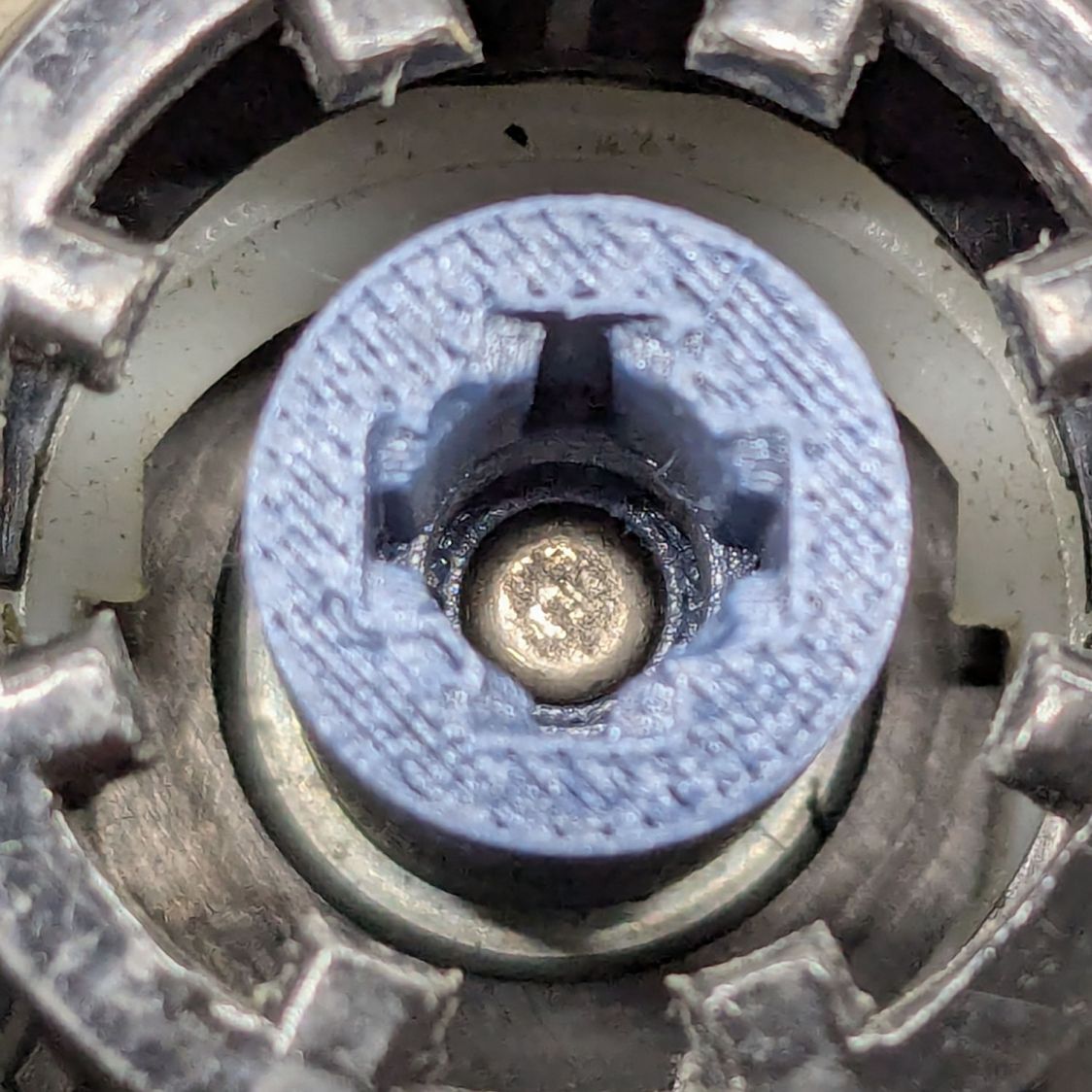
My coupler is chunkier than the OEM coupler, because there was enough room in there and PETG-CF, being weaker than nylon, needs all the help it can get:
Stick blender coupler – new coupler installed
It’s one of the few things I’ve printed with 100% infill. If when that plastic fails, I’ll try something else.
Put the little rubber ring on the blade shaft and reassemble everything in reverse order:
Stick blender coupler – mating ends
The blender works as well as it ever did, while the halves couple and uncouple the way they should, so we’ll declare victory and keep the new blender as a backup.
This file contains hidden or bidirectional Unicode text that may be interpreted or compiled differently than what appears below. To review, open the file in an editor that reveals hidden Unicode characters.
Learn more about bidirectional Unicode characters
The venerable (circa 1993) Whirlpool clothes dryer (LER443AQ0) that Came With The House™ failed in action: the drum occasionally stopped turning (and, fortunately, heating) while the control timer continued ticking along. The symptoms suggested one of the many thermal switches / thermostats / fuses was bad, but because the problem was intermittent, the only practical alternative was replacing all the things.
Which, it turns out, costs about ten bucks from the usual source. I remain unconvinced paying an order of magnitude more for what look to be identical parts will, in fact, bring either different parts or higher quality.
The wiring diagram, which I consulted only after the fact, shows it was most likely the “Not Resettable” Thermal Fuse in series with the drum motor, because the other contestants are in series with the heater and the Operating Thermostat would trip when the blower stopped blowing:
Whirlpool dryer – wiring diagram – detail
The fact that the Thermal Fuse should not “reset” after it trips seems worrisome, but failures are like that.
All those parts are accessible only through the rear cover, but you should definitely vacuum out as much fuzz as possible before popping the cover (with vacuum in hand):
Whirlpool dryer – heater duct top
Of course, all the old parts show fine continuity, because intermittent:
Whirlpool dryer – thermal switches
With the new parts in place, the dryer has chugged through half a dozen loads without incident: so all’s well that ends well.
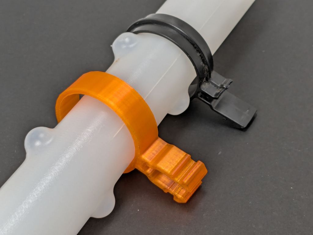
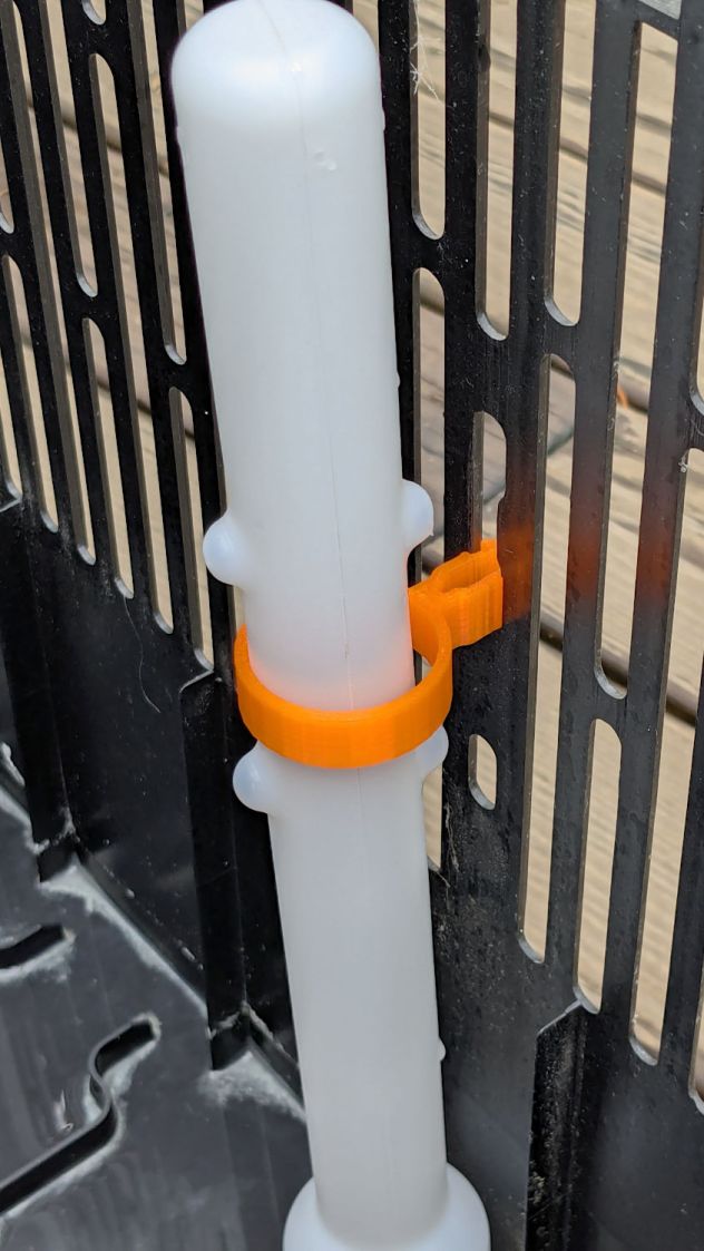
This being the end of the humidifcation season, I tried to set the longsuffering Sears Humidifier’s water level float to dry the thing out. After a few days, it became obvious that wasn’t working and I eventually found the clip intended to hold the float at the top of its travel had broken:
Humidifier float clips – on float
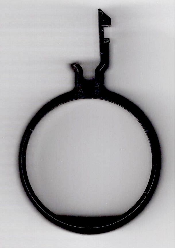
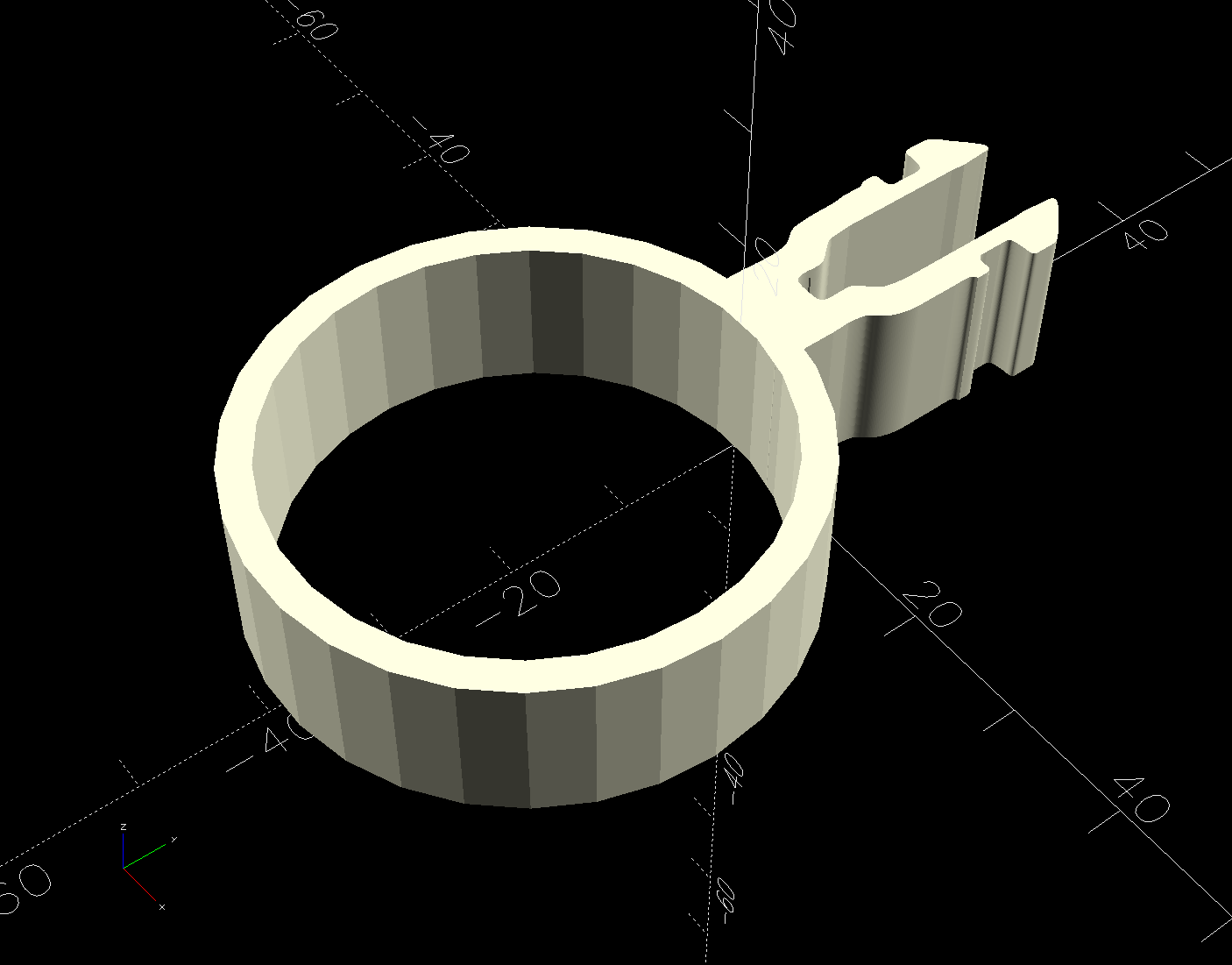
Building the retina-burn orange replacement started with a scan of the original:
Humidifier float clip
The black segment at the bottom is a shadow due to the scanner’s light bar being offset from the imaging sensor.
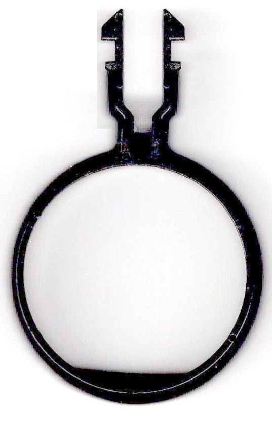
Using GIMP, duplicate the remaining part of the latch, flip it left-to-right, then align it at the proper position:
Humidifier float clip – repaired
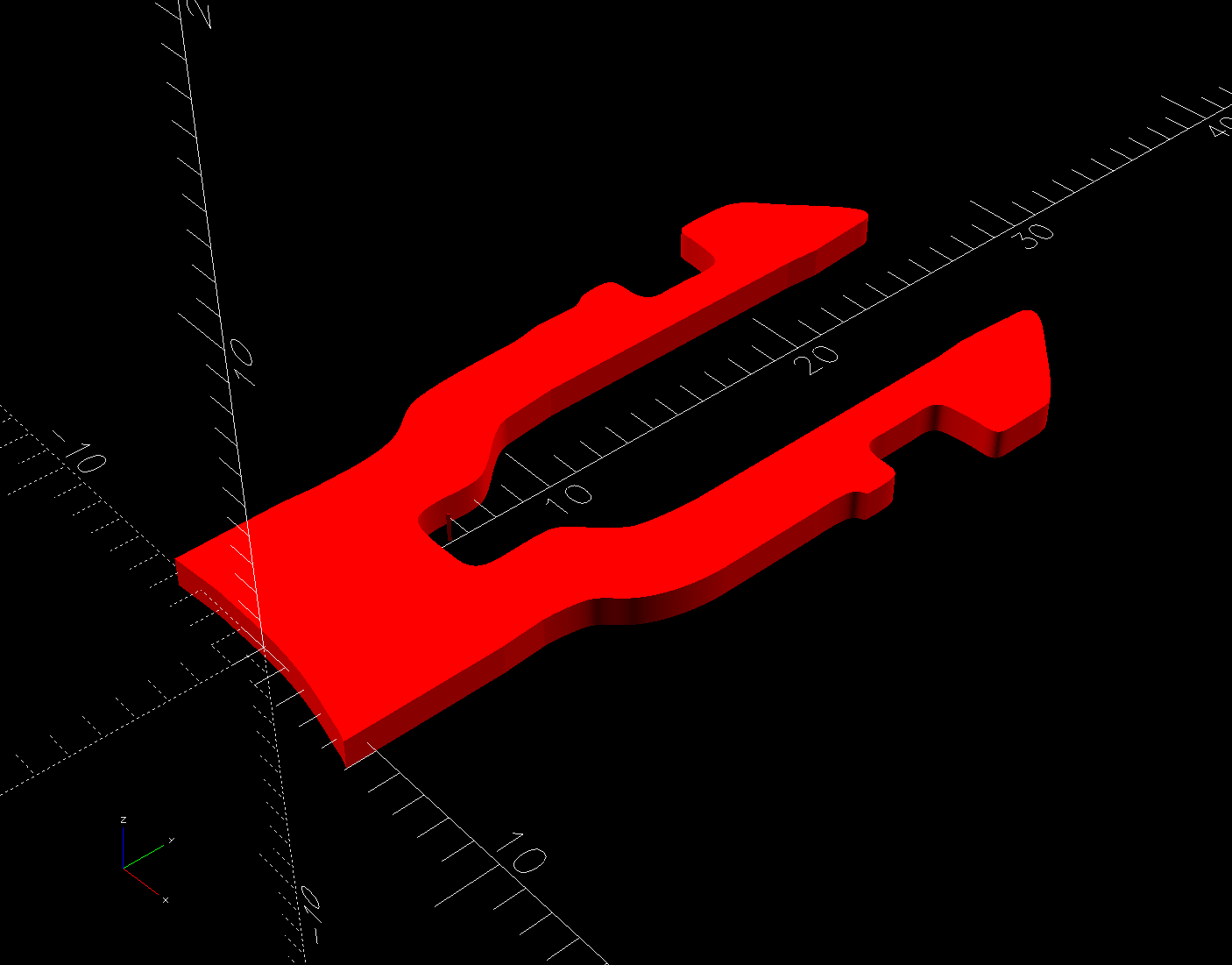
The latch is the only tricky part and the ID of the ring is easy to locate, so (still in GIMP):
Trace the edge of the whole shape
Using Quick Mask mode, remove all but the latch
Convert the selection to a path
Export it as an SVG file
Then import it into OpenSCAD and eyeballometrically translate the shape to put the ring ID at the origin:
There being no obvious affordance to get the ring over the two bumps in the float, I applied Channellock pliers to the float while easing the ring into place.
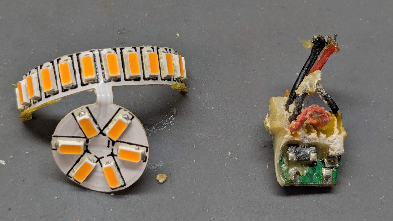
Six years ago I replaced the W5W incandescent front side marker bulbs in our 2015 Subaru Forester with amber LED bulbs:
Side Marker bulbs – failed adhesive
The adhesive holding the LED PCB to the aluminum “heatsink” has fossilized and the strip on the right is peeling off (with the left one not far behind), which likely accounted for its loss of light output and flickering.
Tearing it apart reveals the LED layout and what looks like a bridge rectifier or a big resistor (to fool the CAN bus?) on a tiny PCB jammed inside the shell:
Side Marker bulbs – rectifier
The other side of the PCB could be a buck converter:
Side Marker bulbs – buck converter
In round numbers, we’ve driven 18000 miles at an average of maybe 40 mph over those years; call it 450 hours. However, the side marker lights aren’t on unless the headlights are on; we do very little night driving, which means those LED bulbs are the usual crap.
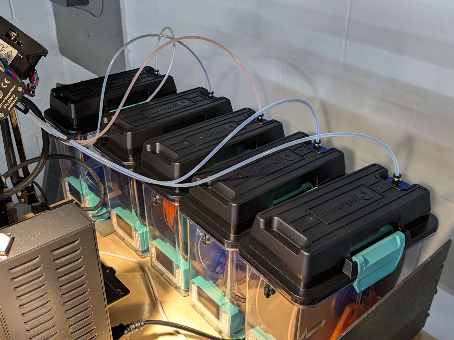
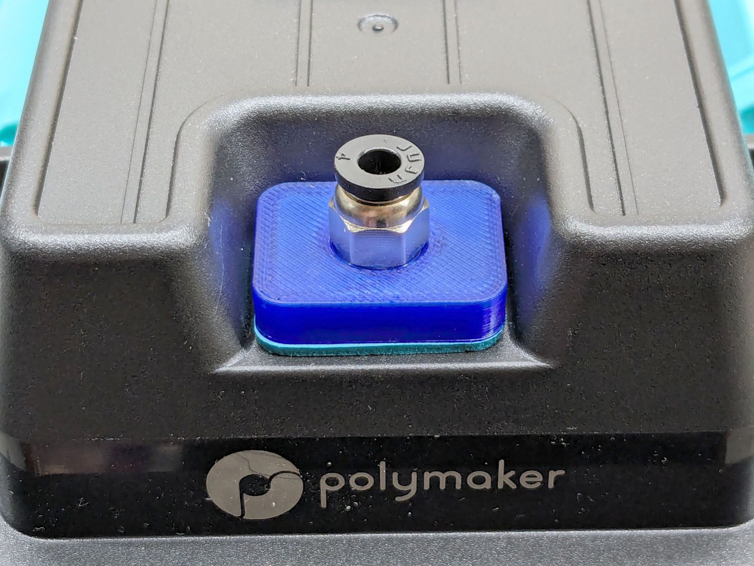
Their rubbery port covers work best with 6 mm OD PTFE tubes, but let the MMU3’s 4 mm tubes slide into / out of the boxes under normal filament extrusion / retraction forces, so I conjured an adapter for PC4-M10 pneumatic fittings:
PolyDryer PC4 Fitting – installed
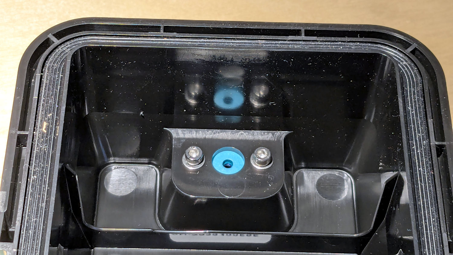
A pair of M3 screws hold the adapter plate in place, with an EVA foam gasket sealing against the cover:
PolyDryer PC4 Fitting – interior view
The PC4-M10 fittings let the 4 mm tubing slide right through, so the adapter has a 0.5 mm bottom sheet to block the tube, with a small hole for the filament:
PC4 Fitting Plates – bottom – solid model
You could use PC4-M6 fittings to block the tubing, but the 2 mm lumen on the fittings I have barely pass 1.75 mm nominal filament. Comments found elsewhere suggest identical PC4-M6 fittings have smaller lumens that snag the filament as it moves in one direction or the other.
The two blind holes get heat-staked 4×4mm M3 brass inserts.
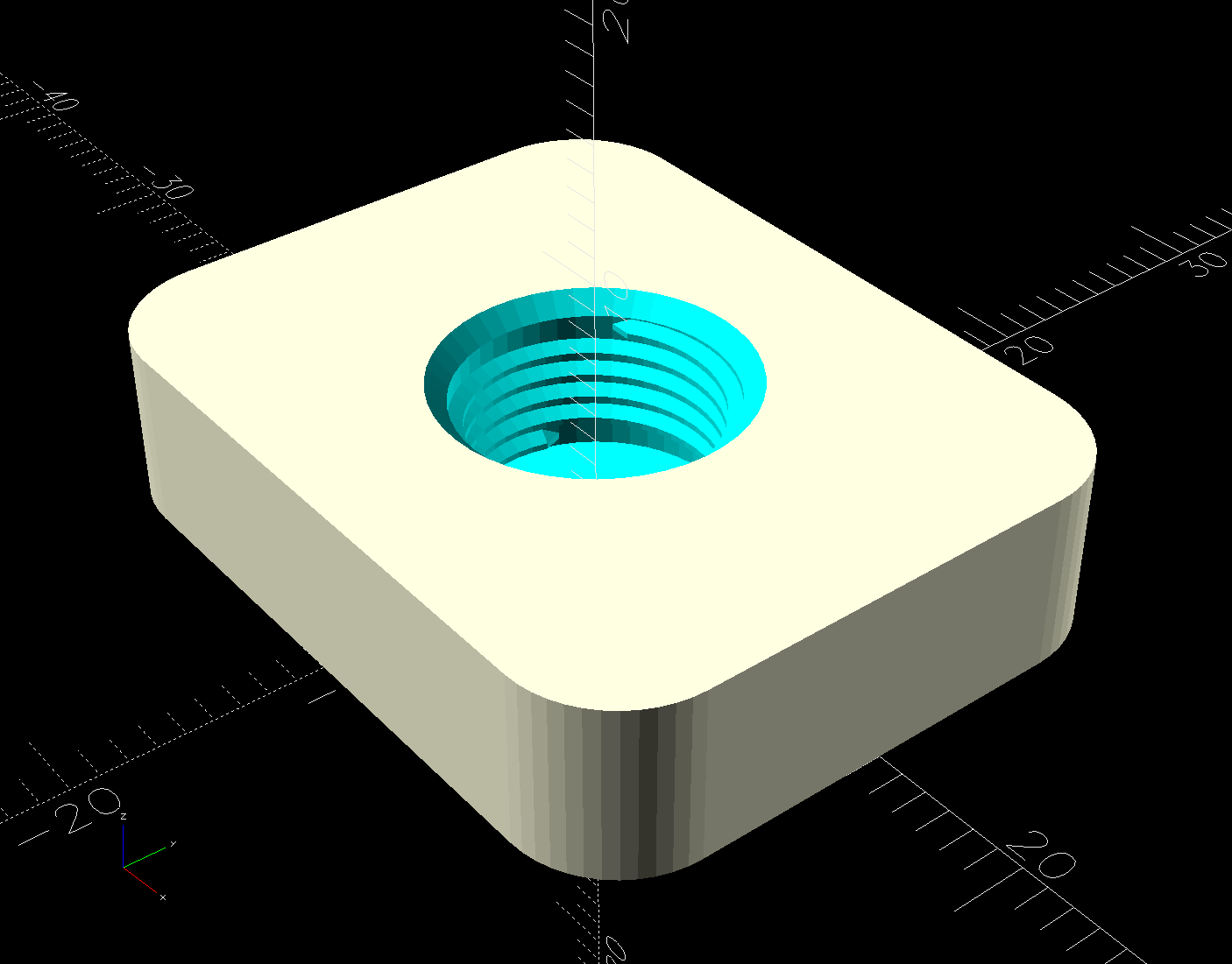
The top has a threaded hole for the fitting:
PC4 Fitting Plates – top – solid model
Despite what the description says, the thread is not an M10 metric straight thread: it is a tapered pipe thread used for gas- and liquid-tight fittings. Considerable measurement & searching suggested a ⅛BSP-28 thread, because:
British Standard Pipe threads are used everywhere in the world except the USA
Both my metric tap sets have a ⅛BSP-28 tap along with all their hard-metric straight taps
The thread is painfully close to ⅛NPT-27, which would probably work in a pinch if it was the only tap you had.
Those PC4-M6 fittings might sport 1/16BSP-28 threads, but you’re on your own.
Further searching suggests nobody uses the corresponding tapered female pipe threads and everybody goes with a straight internal thread, so I conjured a stumpy threaded rod using the BOSL2 library and removed it from the adapter plate:
The 9.7 mm diameter is the ⅛BSP-28 “major diameter”, rather than its “gauge diameter”, simply because it produced a good fit. The beveled top guides the fitting into the hole, but I still managed to cross-thread one.
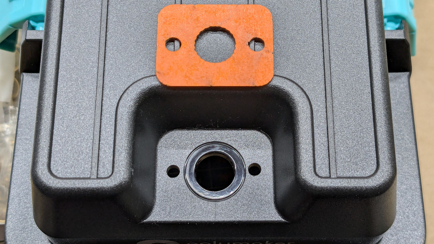
The OpenSCAD code also produces SVG files to laser-cut the foam gasket and a drill template:
PolyDryer PC4 Fitting – drill template
The holes were step-drilled to ⅛ inch (which has a historic relation to the ⅛BSP-28 size, because iron pipe) for a generous fit around the M3 screws.
That was way more complicated than I expected and I’m really glad to live in the future where this is a 3D printer project, not a metalworking project involving an actual tap in, say, steel.
This file contains hidden or bidirectional Unicode text that may be interpreted or compiled differently than what appears below. To review, open the file in an editor that reveals hidden Unicode characters.
Learn more about bidirectional Unicode characters
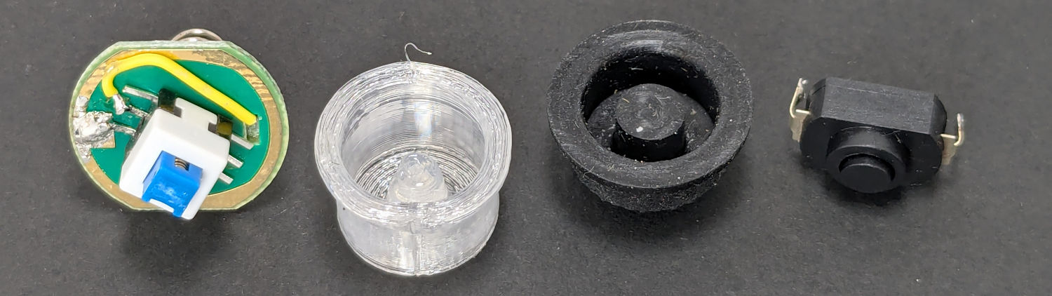
The switch on the Anker LC-40 flashlight serving as a running light on my Tour Easy became slightly intermittent before I replaced it with a 1 W amber LED, but it was still good enough to become the troubleshooting flashlight in the tray next to the Prusa Mk 4 printer. Eventually, of course, it failed completely and Something Had To Be Done.
Although I knew an exact replacement switch had to be available from the usual sources, I could not come up with a set of keywords capable of pulling them out of the chaff.
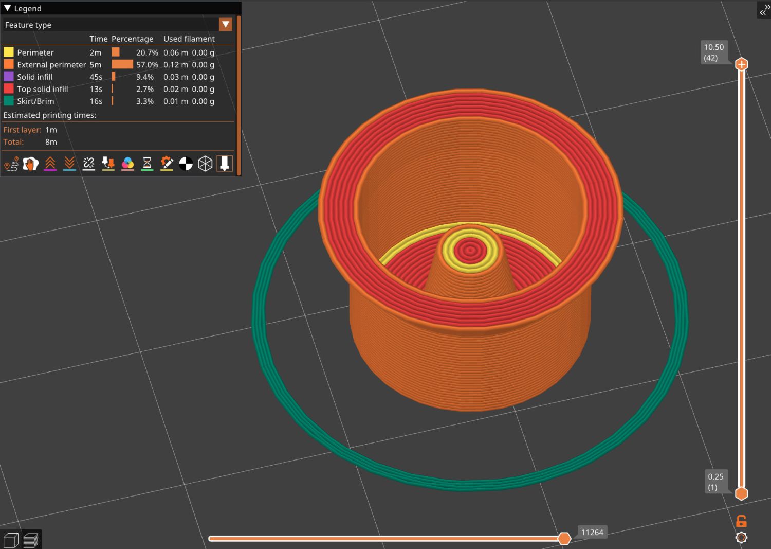
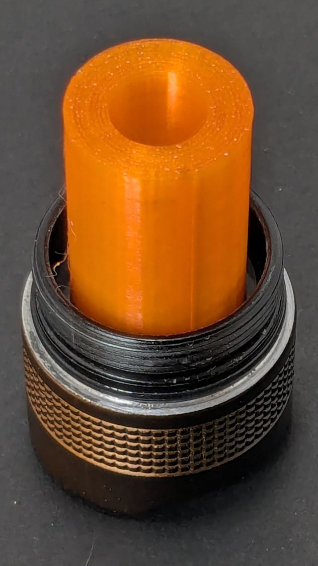
Which turned into a multi-dimensional search over cap geometry, TPU extrusion speeds & feeds, and various impossible-to-directly-measure sizes:
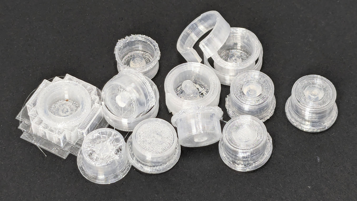
Anker LC-40 Flashlight – TPU cap iterations
The squarish block over on the left is PrusaSlicer’s version of a support structure wrapped around the first cap version; if human lives depended on it, I could surely extract the cap, but it would take a while.
The remaining debris samples occured while discovering:
An extruder temperature of 230 °C, not 250 °C, works well
A conical shape of the lip around the open end to eliminate the support structure
TPU doesn’t bridge well, so the closed end must be down
Length of the central pillar to barely touch the switch stem when released
Cap length and wall thickness so the TPU shell can collapse enough to actuate and release the switch stem
Because I expected this would be an easy job, I used snap ring pliers to unscrew and rescrew the threaded retaining ring holding the switch PCB in place. Because the pliers didn’t have a stable grip on the ring, the threads eventually became just a bit goobered.
This was not a problem, because I have a(nother) 3D printer:
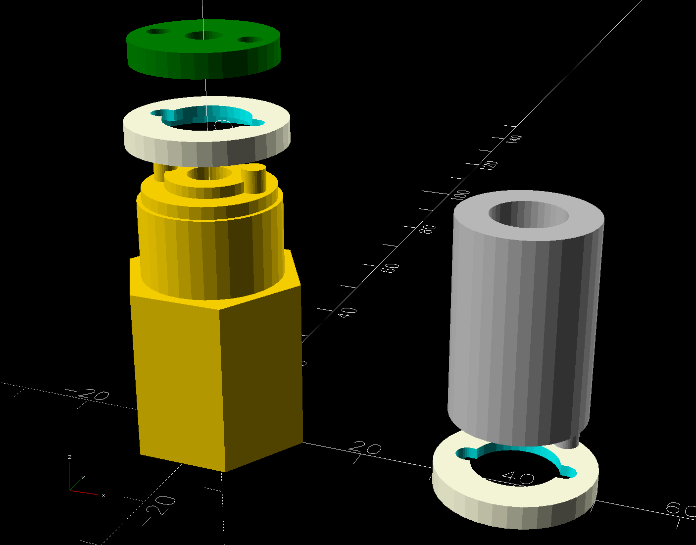
Anker LC-40 Flashlight Retainer – show view
The gray thing on the right is a simple pin wrench fitting both the original and the replacement retaining rings, so I can orient the rings properly while unscrewing & rescrewing:
Anker LC-40 Flashlight – pin wrench in place
The threads have a 0.75 mm pitch and, while it’s possible to print screw threads, even a tedious 0.1 mm layer height would define each turn of the thread with only 7-½ layers.
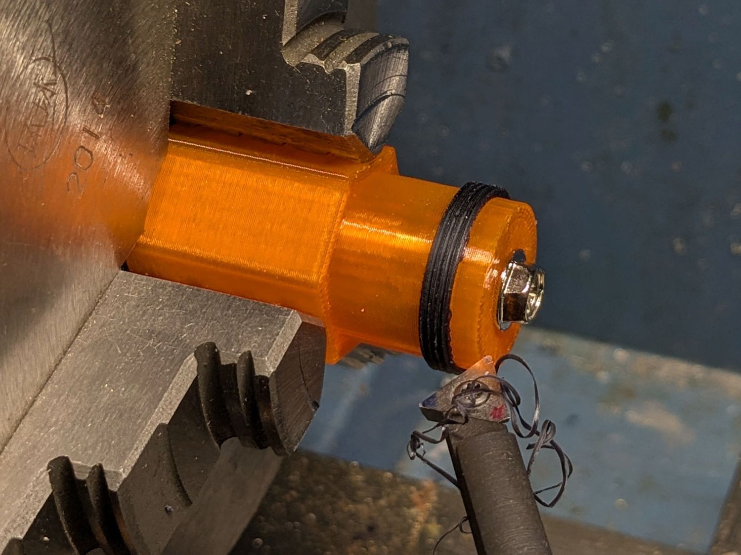
This was not a problem, because I have a mini-lathe:
Anker LC-40 Flashlight – thread cutting
The yellow & green things on the left of those solid models are the fixture holding a retaining ring for threading and the washer applying pressure to keep the ring in place:
Anker LC-40 Flashlight – lathe fixture – detail
The alert reader will note that washer lacks holes for the alignment pins I added after seeing the washer sit not quite concentric on the fixture. I could call it continuous product improvement, although I doubt I’ll print another one.
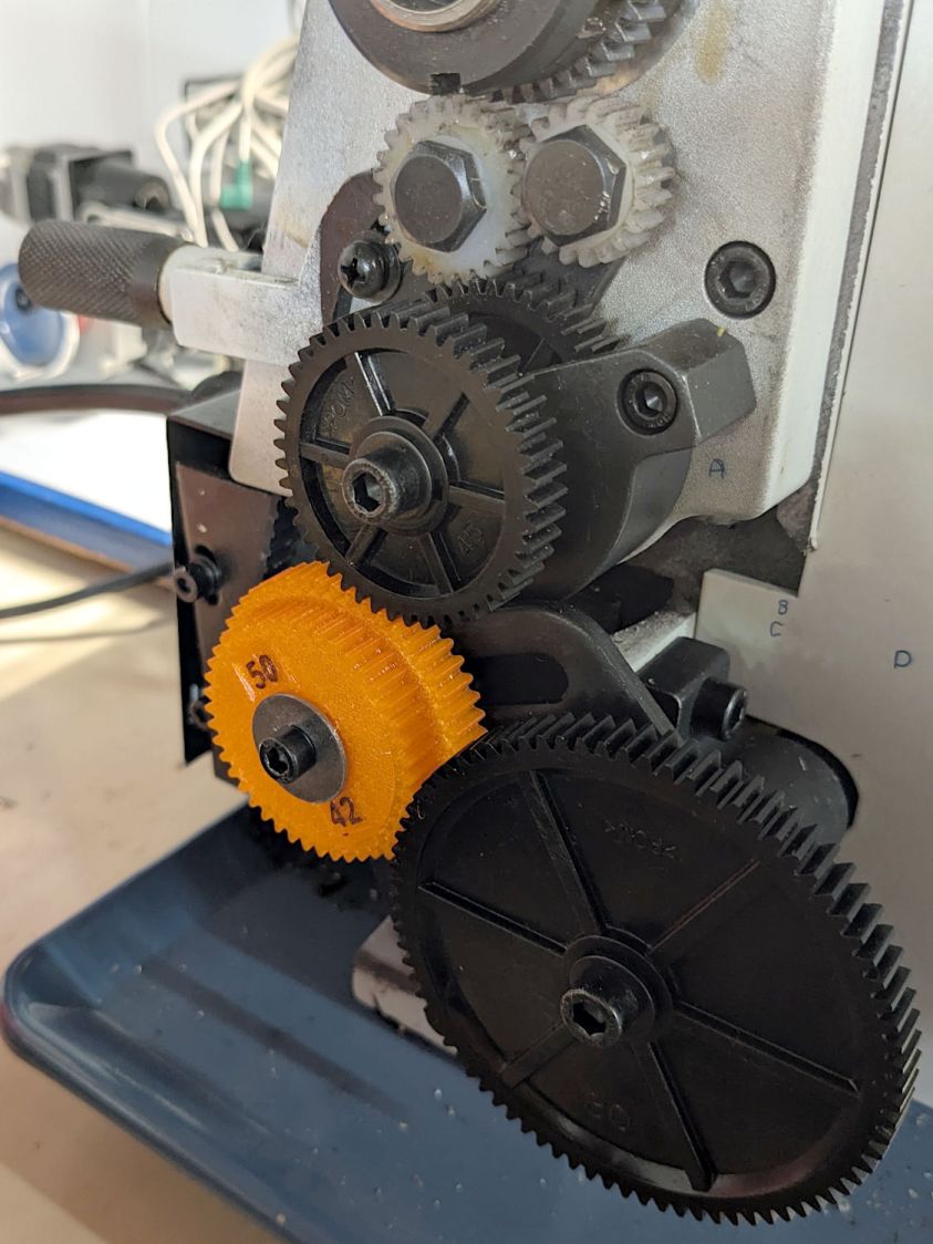
Setting up the lathe involved finding the proper set of change gears, including the vital 42-50 stacked gear I made a while ago to print metric threads on a hard-inch lathe:
Anker LC-40 Flashlight – lathe change gear train
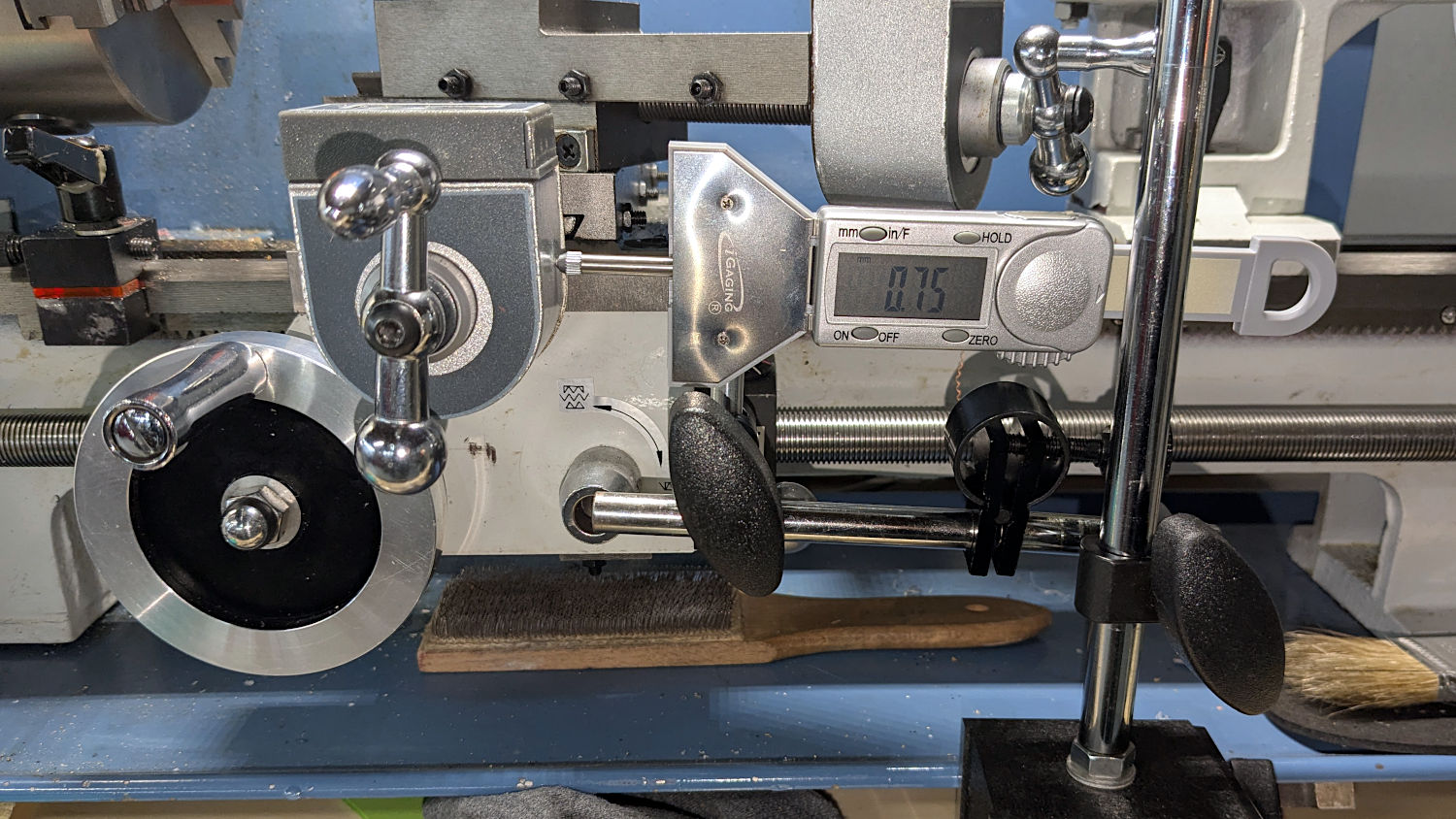
Although you’re supposed to measure the thread spacing on a skim pass, I find it’s easier to just measure the carriage movement for one spindle rotation:
Anker LC-40 Flashlight – lathe gear check
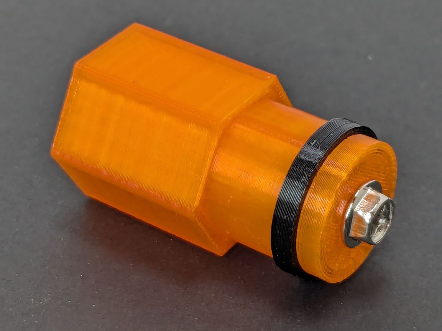
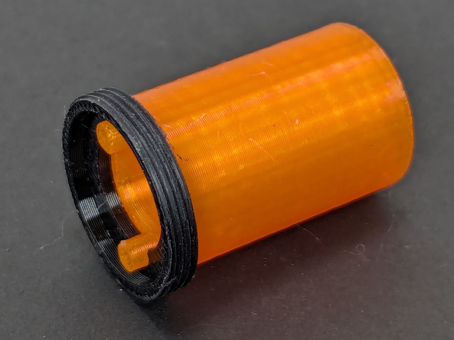
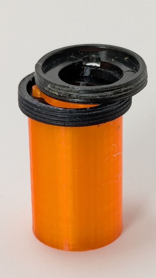
A few passes produced a fine retaining ring:
Anker LC-40 Flashlight – OEM vs lathe-cut threads
Sporting much nicer looking threads than the goobered original:
Anker LC-40 Flashlight – OEM vs lathe-cut threads
The original switch had a stabilizing ring around the body to prevent it from wobbling under the original rubber cap.
This was not a problem, because I have a laser cutter:
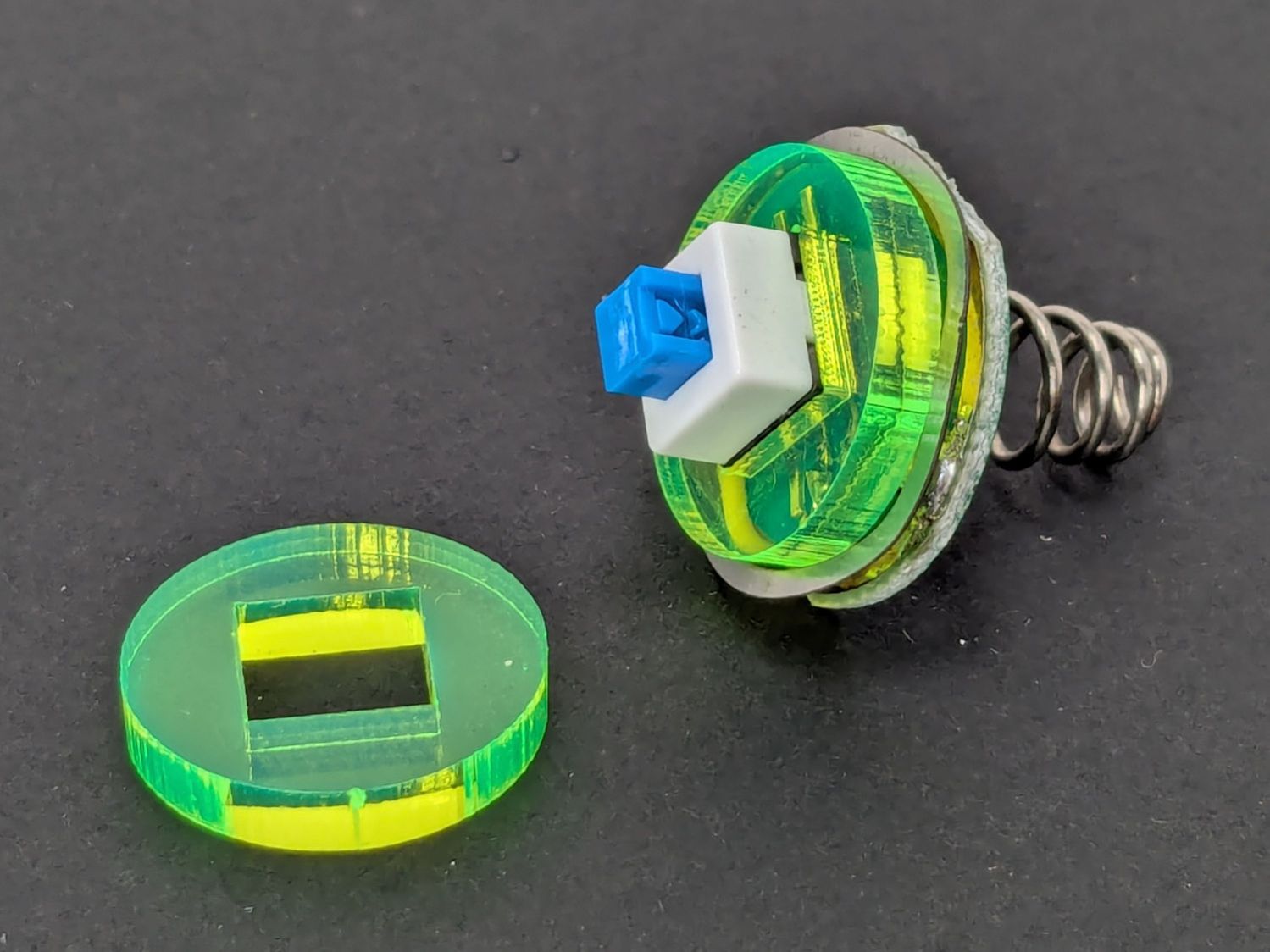
Anker LC-40 Flashlight – new switch in stabilizer
Those came from a scrap of fluorescent acrylic.
The wave washer behind the acrylic stabilizer improves the contact between the PCB trace around the rim and the flashlight tailcap, with the current passing through the body to the “light engine” up front. The retaining ring provides enough pressure to compress the wave washer, which is why it’s so easily goobered without a close-fitting pin wrench.
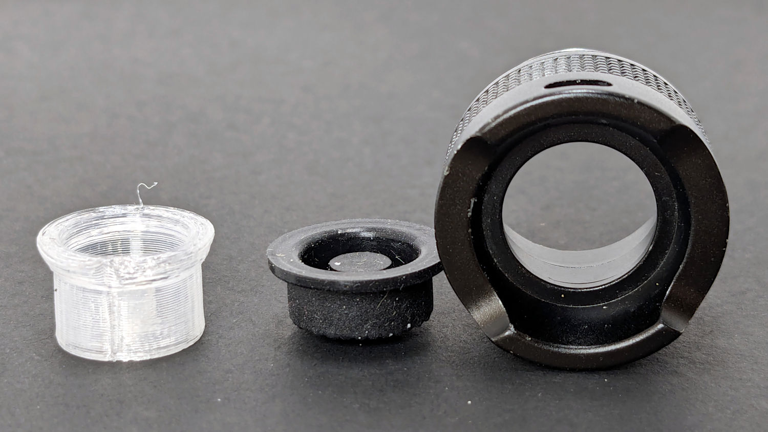
With everything assembled in reverse order, the flashlight worked pretty much as it did back when it was new:
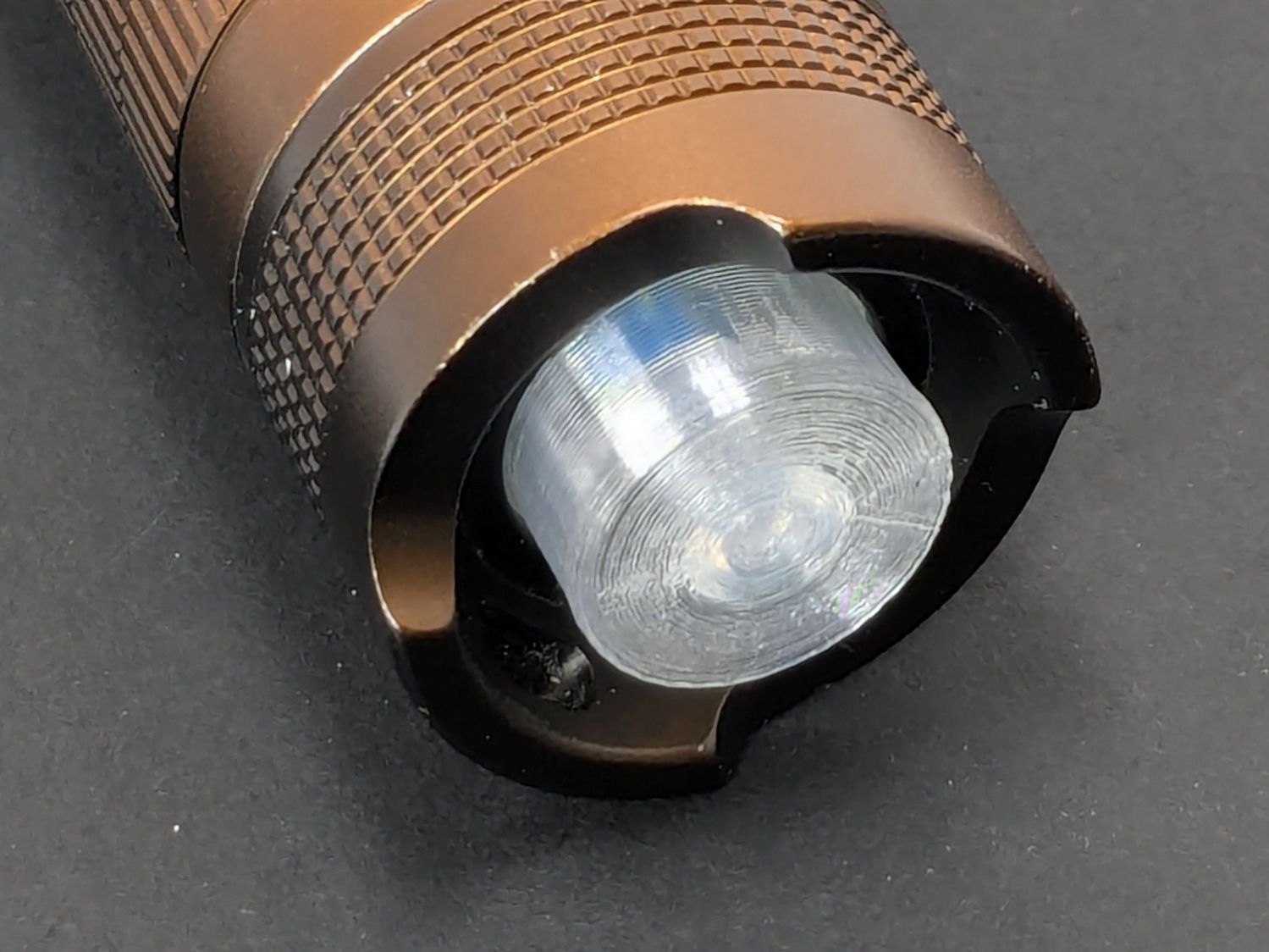
Anker LC-40 Flashlight – TPU cap installed
However, after describing this during a recent SquidWrench meeting, I discovered that adding “latching” to my keywords surfaced a bodacious assortment of flashlight switches, so (a few days later) I removed the not-quite-right switch and replaced it with an identical twin of the OEM switch requiring just a little lead forming to fit the PCB.
Even better, using the 3D printed pin wrench to screw the original retaining ring into the flashlight’s aluminum threads a few times re-formed (unrelated to recent electrolytic capacitor reforming) its goobered threads well enough to fit and work perfectly again.
So I have:
… reassembled the flashlight with more-or-less original components
… a repair tool kit ready when another LC-40 fails
… re-learned the lesson that any time spent making a fixture or a special tool is not deducted from one’s allotment
This file contains hidden or bidirectional Unicode text that may be interpreted or compiled differently than what appears below. To review, open the file in an editor that reveals hidden Unicode characters.
Learn more about bidirectional Unicode characters


