The minimal instruction manual for the rivnut setting tool I’ve been using doesn’t explain how far to compress the rivnuts . The somewhat better manual for a similar tool includes a table:
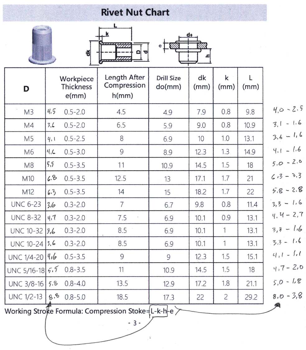
Under the plausible, but herein undefended, assumption that all rivnuts of a given size from any source are identical, the first three terms of the formula for each size become the number penciled into second column. Subtracting the range of material thickness from that number produces the stroke length range penciled over on the right.
Neither manual explains how to set the tool to a specific stroke length, although eyeballing the distance on the scale from first contact until the going gets tough seems to cover smaller rivnuts:
Stop applying more power on the handles when the decrease in the distance on the gauge approaches the calculated working stroke.
For larger rivnuts, you just hit it again, harder:
turn the knob clockwise to bring the riveter closer to the rivet nut, and close the handles until the rivet nut is secure in the hole. Repeat as necessary until the rivet nut is firmly in place.
This post is my attempt to figure out how to adjust the tool to a specific stroke length, mostly because I’m that type of guy.
Start with a diagram from the manual naming the parts:
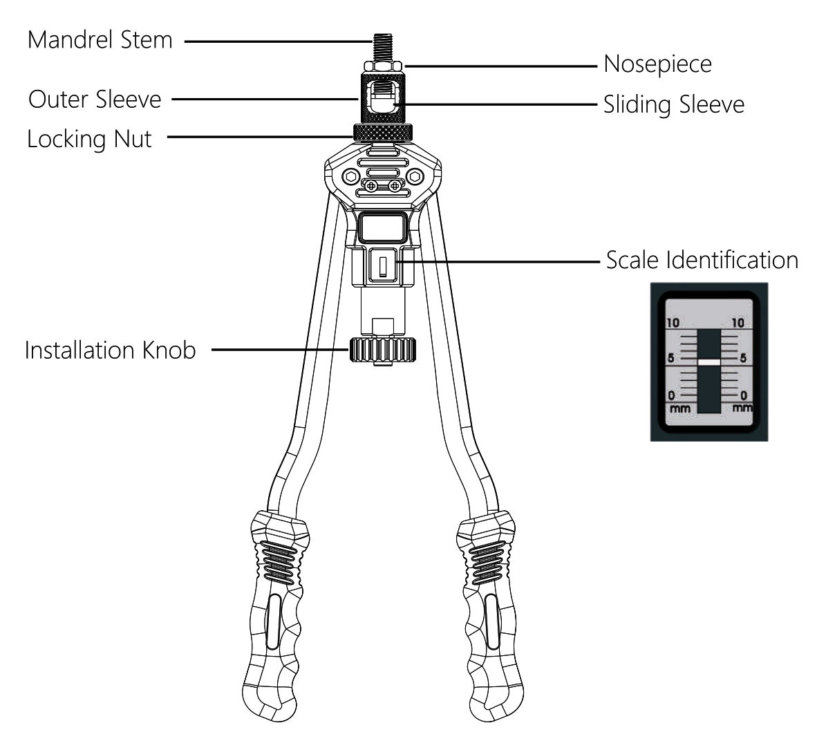
The unlabeled black cylinder between the “Installation Knob” and the “Scale Identification” is a nut determining the zero setting of the scale with the handles closed:
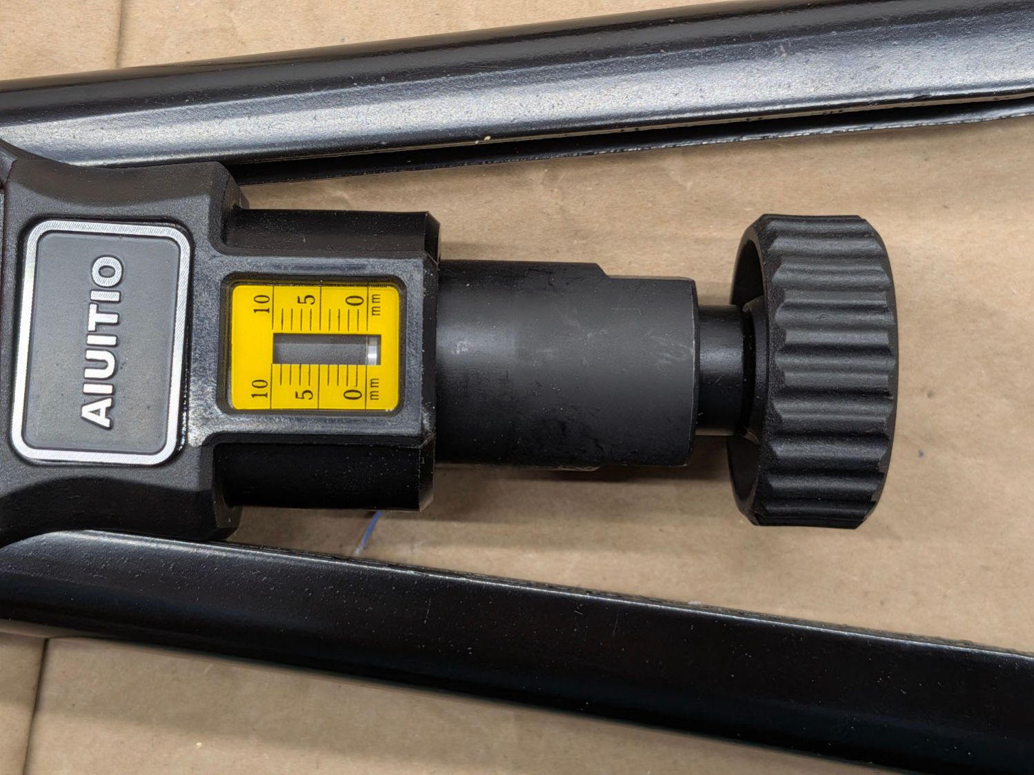
Presumably that nut should be snug-to-tight with the scale at zero, because loosening it pushes the knob away from the body and puts the scale indicator below zero. It was finger-loose on my tool, so I snugged it firmly. A thin shim would align an indicator starting above zero with a snug nut; there may be an internal adjustment, but I didn’t go there.
The diagram does not show that the “Sliding Sleeve” is spring-loaded away from the tool body:
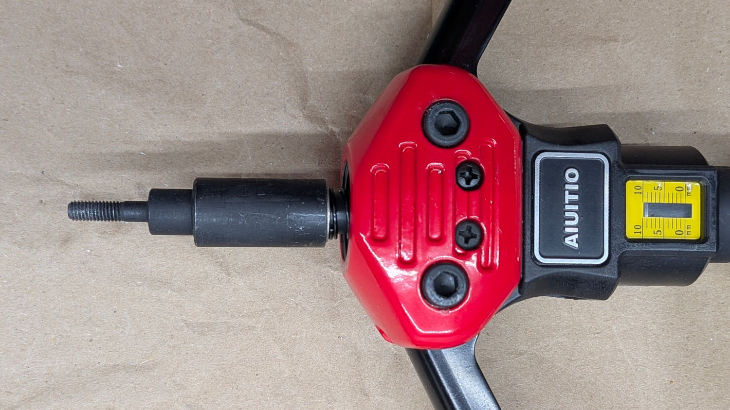
The “Outer Sleeve” normally covers the Sliding Sleeve and hides the spring:
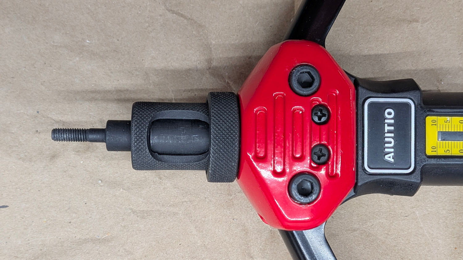
Which makes it awkward / difficult / painful to slide the sleeve toward the body while installing the “Mandrel Stem”, because you’re supposed to reach through those two openings, pinch the sleeve, and push it against the spring:
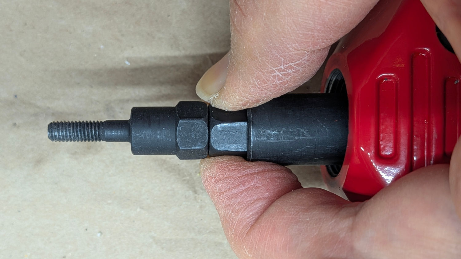
The Mandrel must screw completely into the Sleeve to engage all its threads, then back out a fraction of a turn to align its hex flats with those on the nut inside the Sleeve. Releasing the Sleeve covers both hexes and locks the Mandrel in that position:
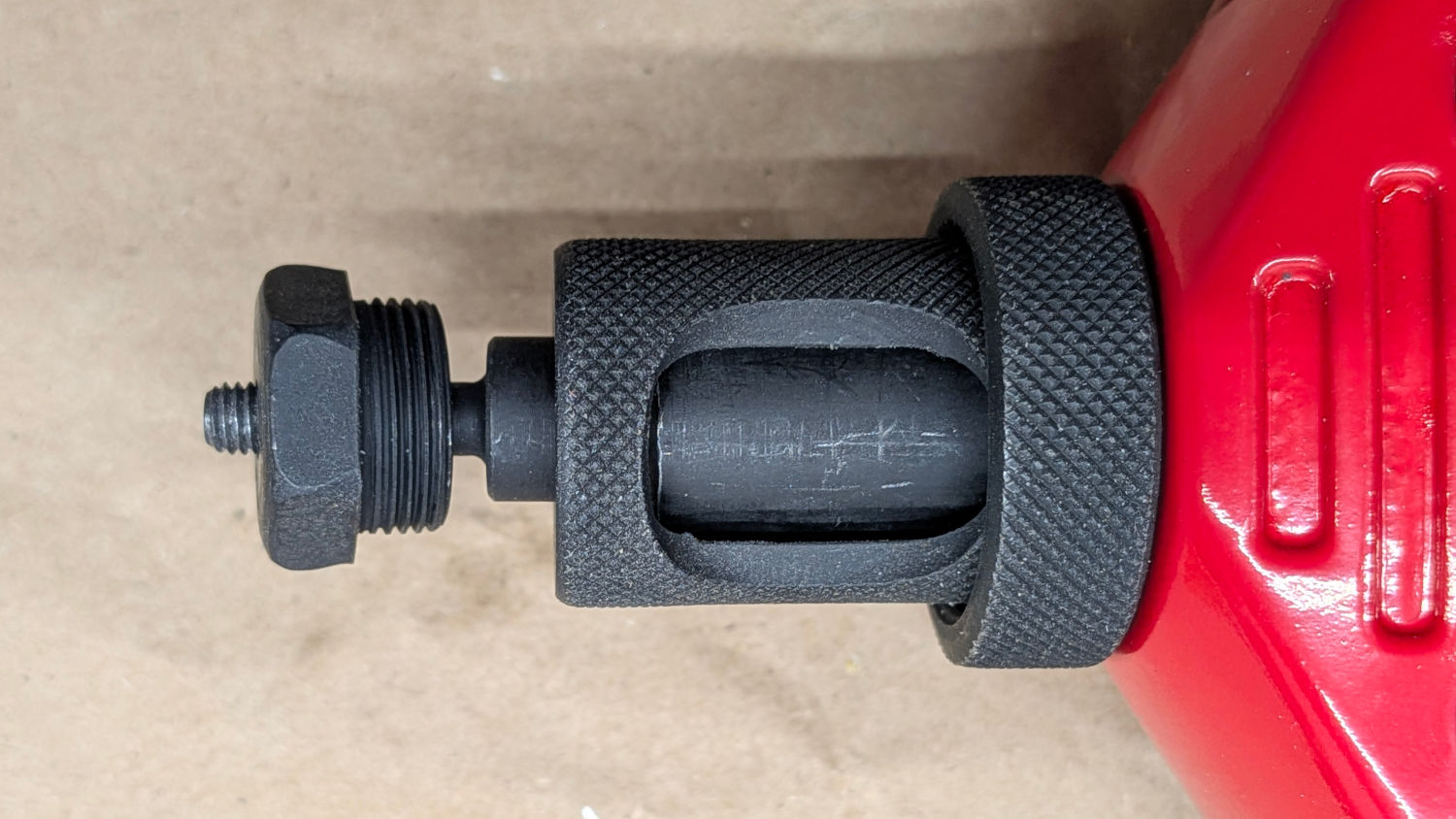
A solid shaft connects the nut inside the Inner Sleeve (and, thus, the Sleeve and Mandrel) to the Knob. Turning the Knob turns the Mandrel, which is how you unscrew the Mandrel from the rivnut after crunching it in the workpiece.
The “Nosepiece” screws into the Outer Sleeve until it seats:
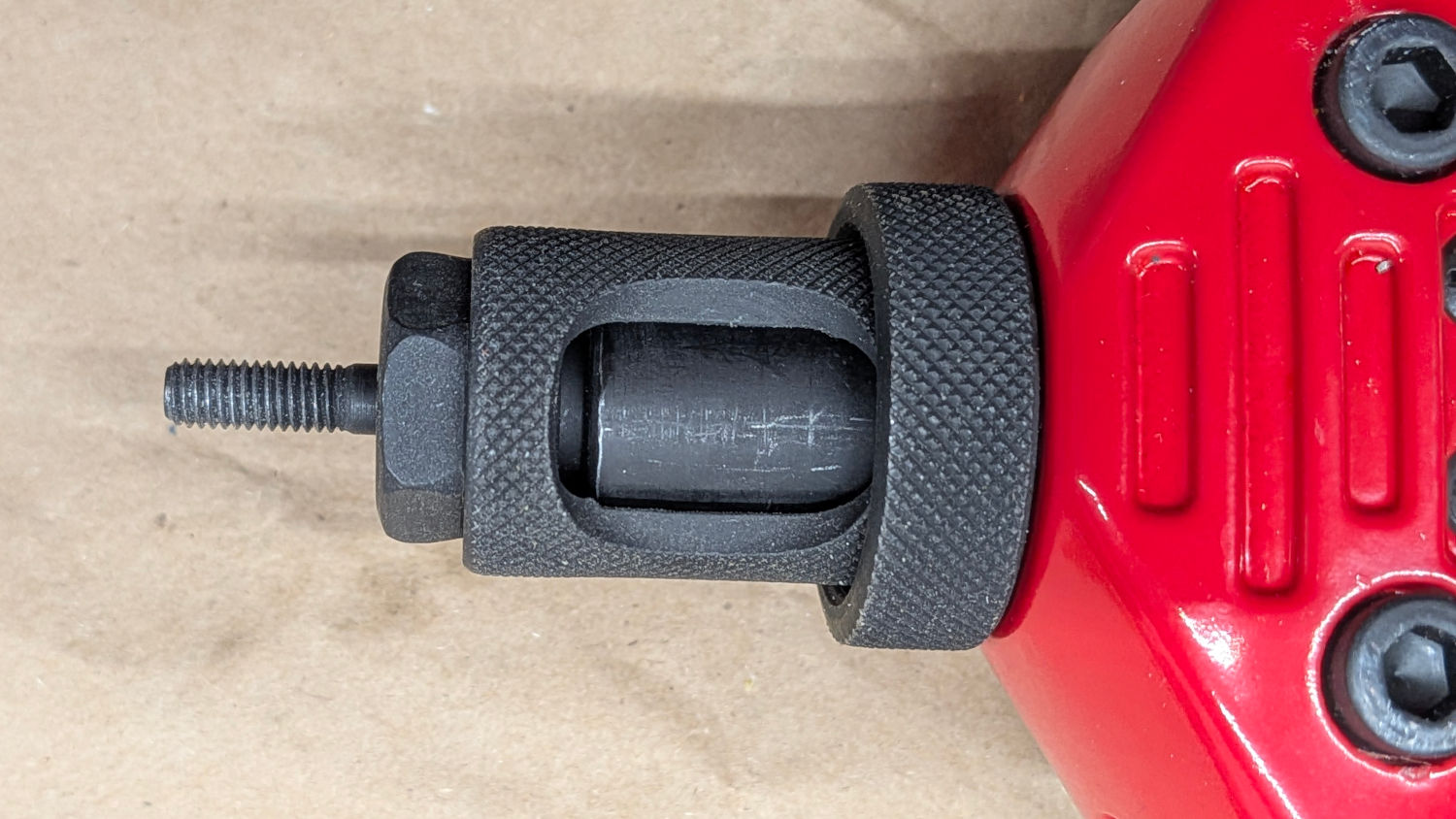
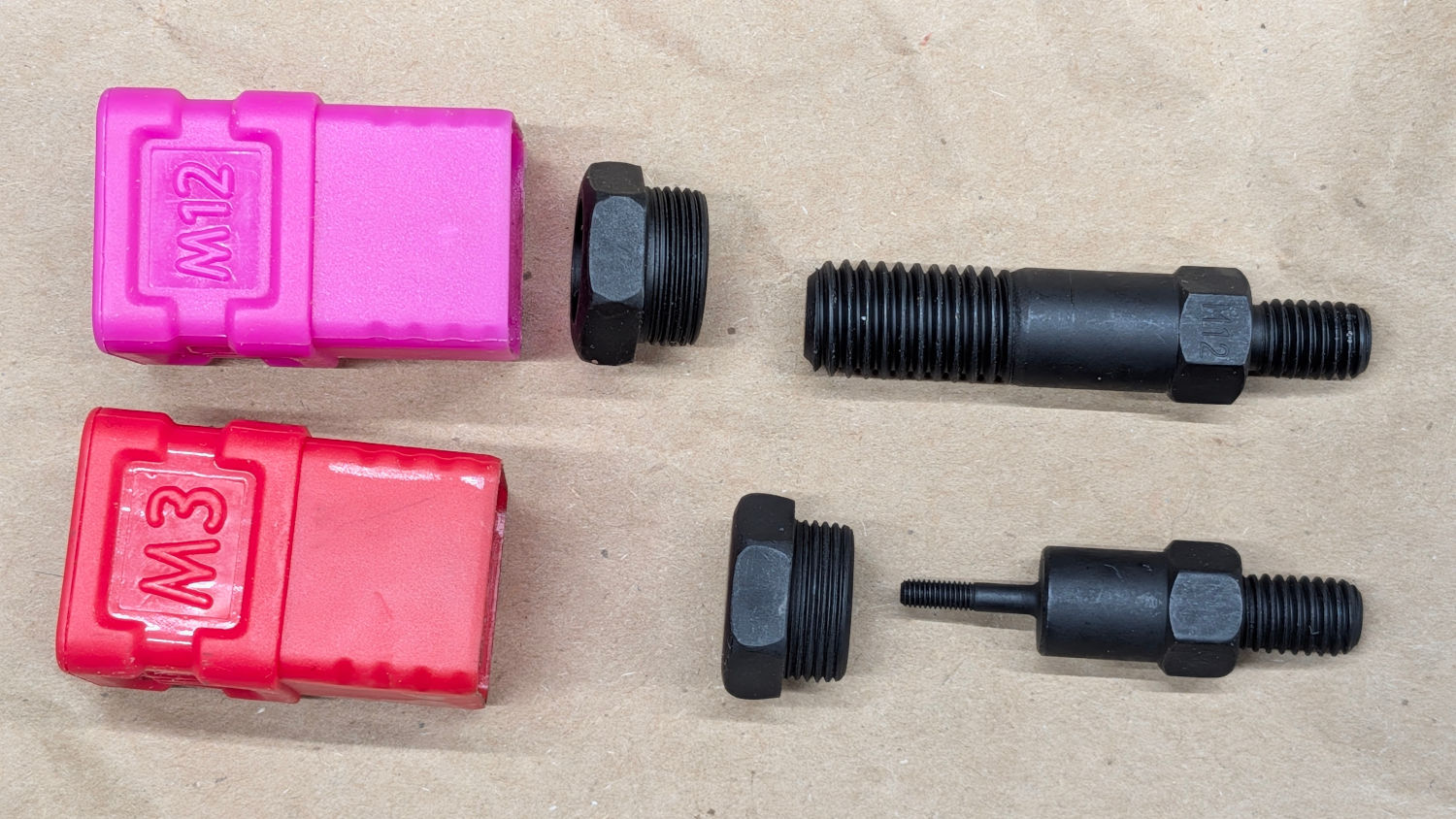
Each Mandrel and Nosepiece corresponds to a specific screw thread, so the Mandrel length & shape depend on the thread:
You might expect this rivnut to be compressed by 10 mm when you close the handles:
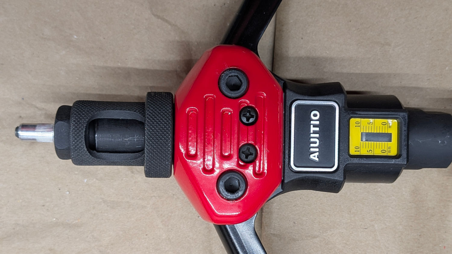
You would be wrong, as was I.
Since this is the rivnut’s first appearance, note that the rivnut is screwed onto the Mandrel to show a thread or two of the Mandrel. The Mandrel must engage all the rivnut threads to prevent stripping the guts out of the poor thing. The plain end of the rivnut (on the left, away from the Nosepiece) has internal threads, as hinted by the diagrams in the chart, with the ribbed end (on the right) being a cylinder collapsing around the workpiece under pressure, which is the whole purpose of the tool.
It turns out the handles will close freely, without applying any force to the M4 rivnut, for about 8 mm of travel:
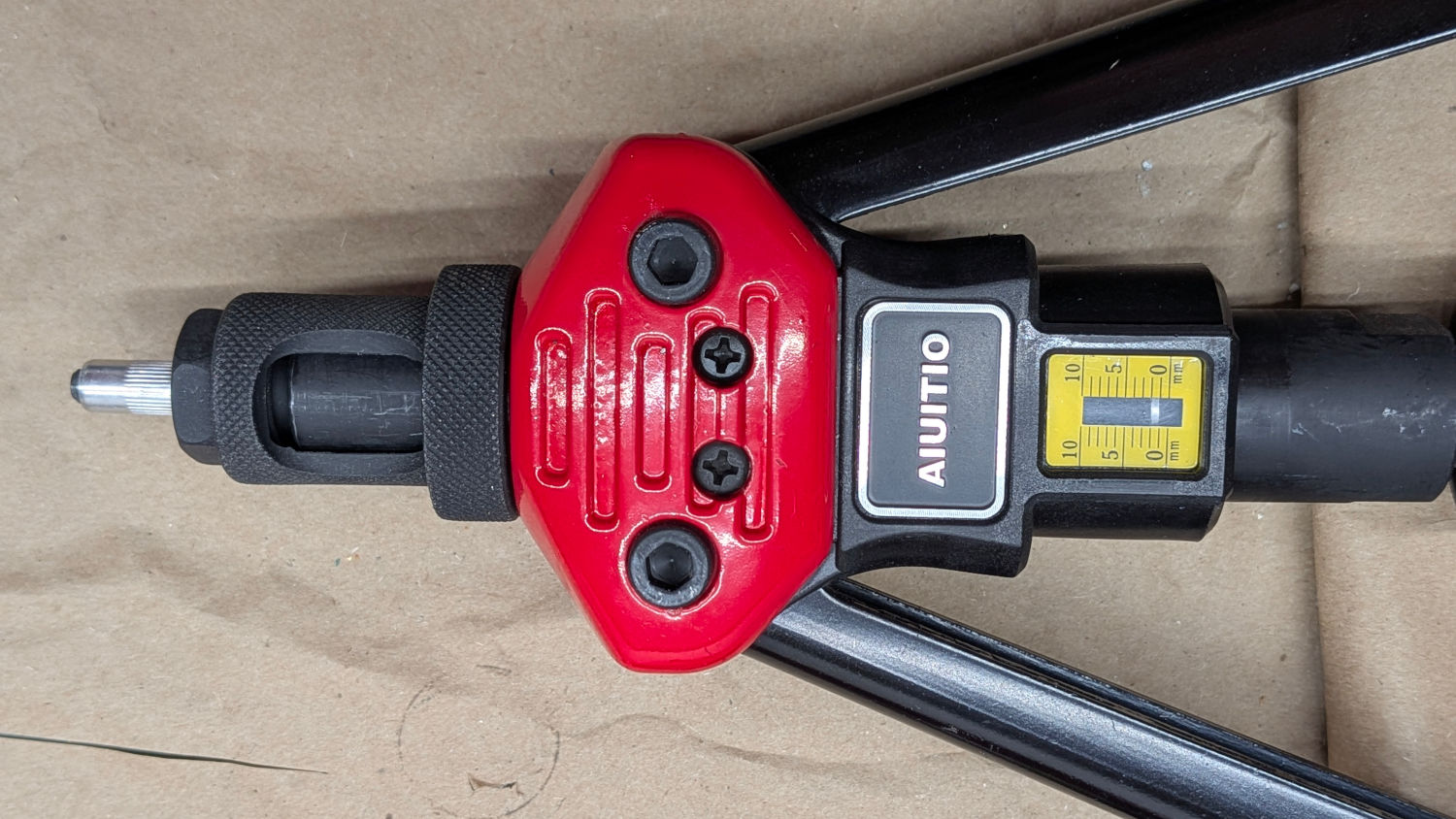
Closing the handles further would compress the rivnut by the 2 mm shown on the Scale.
What was not obvious (to me, anyway): the handles turn cams to push an internal follower toward the Knob. That follower moves 10 mm as the handles go from open to closed, as indicated on the Scale, but won’t move the Mandrel until the follower moves past all the slack caused by compressing the spring. Remember the spring?
Unscrewing the Outer Sleeve to move it outward from the body lets the spring push the Mandrel (and, thus, the Inner Sleeve) away from the body. Do this with the handles extended, so the Scale remains at 10 mm:

Because screwing the Nosepiece into the Outer Sleeve compressed the spring and the Mandrel is on the shaft connected to the Knob, unscrewing the Sleeve also moves the Knob toward the body. Inside the body, the cam follower sees less slack distance, because the spring is less compressed.
The Outer Sleeve (on this tool, anyway) has a 1.25 mm thread, so every revolution outward reduces the spring compression by 1.25 mm. Two turns releases the spring by 2.5 mm and closing the handles until the cam follower meets the shaft now shows 4.5 mm of compression:
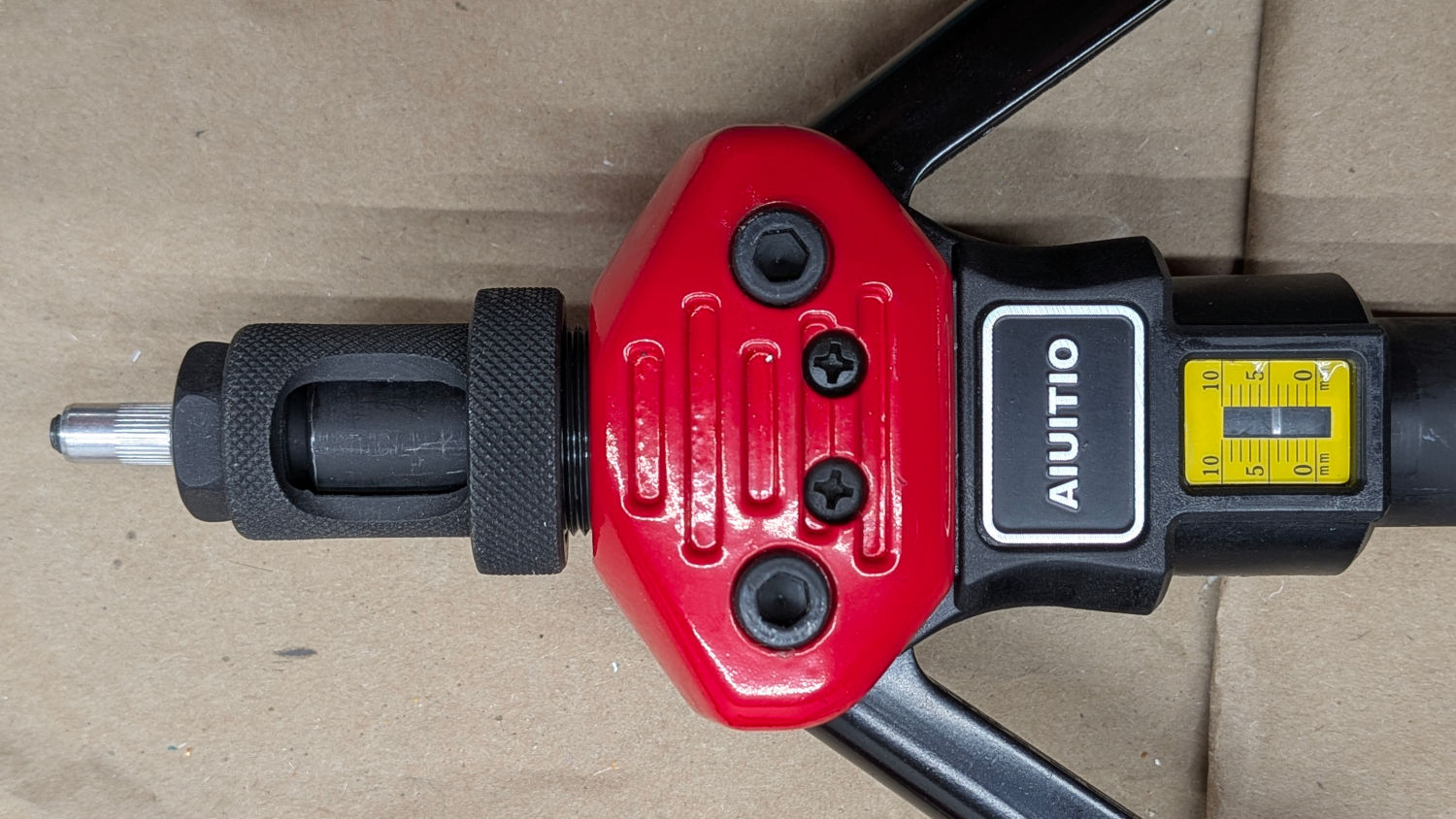
The handles have plenty of slop making this an inexact process, so:
- Open the handles → scale at 10
- Turn the Outer Sleeve to reduce the error
- Close the handles gently until they stop
- The scale shows the actual stroke distance, should you completely close the handles
- Iterate until the correct distance appears
Spin the knurled “Locking Nut” on the Outer Sleeve to contact the tool body, thereby locking the Sleeve in place.
After all that preparation, poking the rivnut into the hole drilled in the material and completely closing the handles should crunch the rivnut Reasonably Close™ to its proper finished length. Assuming you’re crunching more than one rivnut, tweak as needed.
At least I think that’s how it works …


Spam comments get trashed, so don’t bother; you’re not as clever as you think. Comment moderation may cause a delay.