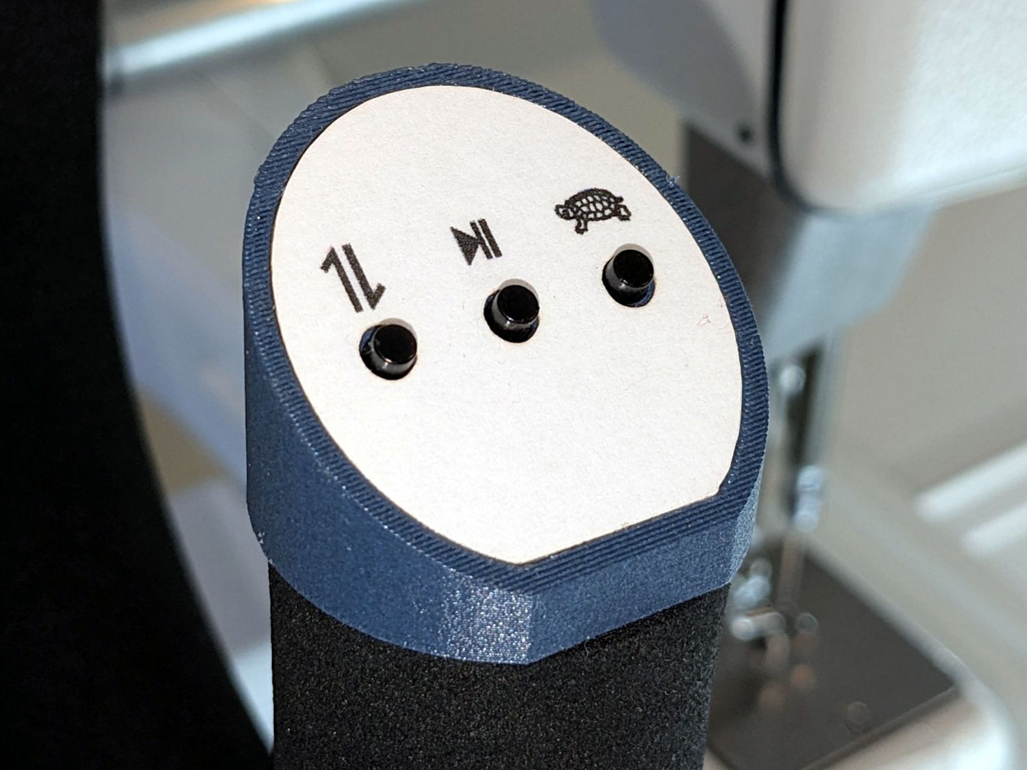
The new control caps on the HQ Sixteen’s handlebars have three switches apiece:
A six-conductor ribbon cable brings those switch terminal through the handlebars, across the smaller PCBs where the original switches plugged in, and atop the main PCB behind / under the LCD panel where they get wired together:
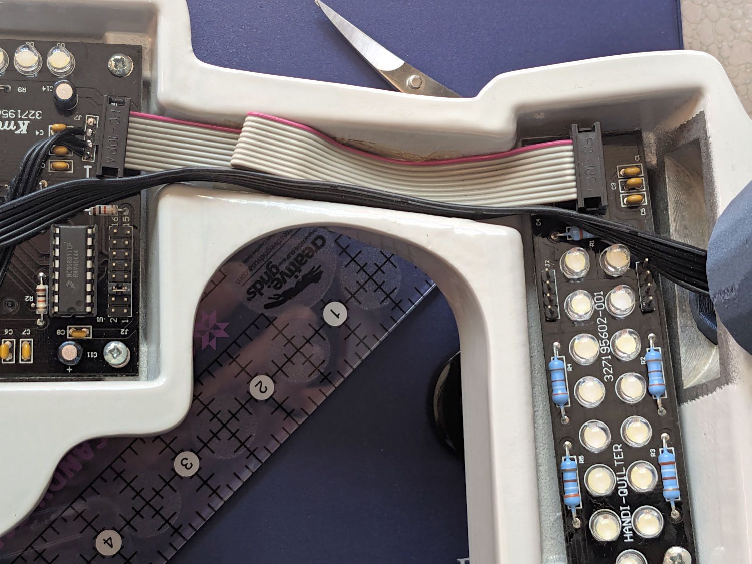
The gray ribbon cable carries power for the LEDs and returns the original switch signals formerly plugged into one of the four-pin headers on the right PCB. The same PCB is used on the other side and the switches over there plug into the other header.
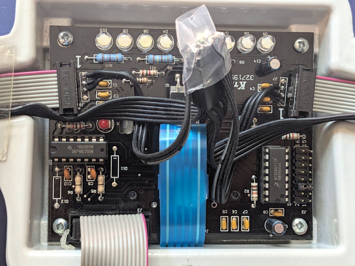
The central PCB is also used for the rear handlebars, which do not have the smaller PCBs, and those switch cables plug directly into four-pin headers mounted instead of the headers for the gray ribbon cables:
Some probing and doodling produced a diagram of the switch connections:
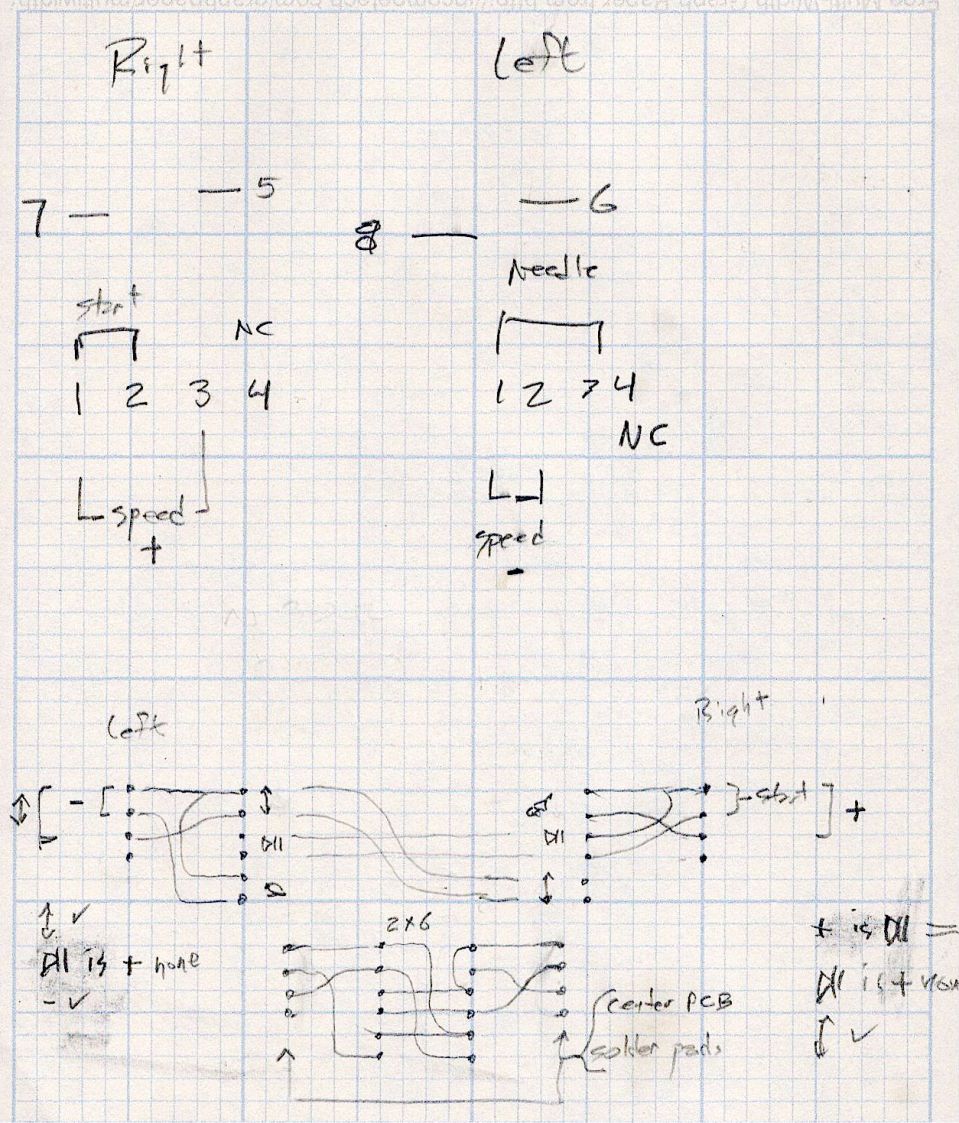
Working with the handlebars either inverted or flipped left-for-right on the workbench makes this far more confusing than it really should be.
In any event, the bottom diagram shows the connections between the two four-pad header positions on the central PCB and the two six-pin headers for the new switches. I used a 2×6 pin header block to plug in the new switches, connected the pins with soldered Wire-Wrap wire, and used three-wire ribbon cable to the PCB pads.
The general idea was to duplicate the Start-Stop and Needle Up/Down switches on both sides, while maintaining the same relative positions of the Fast / Slow switches. In effect, the two new switches on each side are wired in parallel to the original switch pads on the PCB.
Surprisingly, I got the three-wire ribbon cables from the four-pad headers right on the second try, which involved flipping it over. The top and bottom pads on those headers are connected together, so the three-wire cable can go on either way to reverse the positions of the other two wires.
And then the new switches Just Worked™ … whew!

Comments
3 responses to “HQ Sixteen: Improved Control Cap Wiring”
Why not solder headers onto the pads and connect to those?
Mostly simplicity: there’s no room for vertical pin headers + my tall Dupont-ish connectors under the transparent cover. The rear handlebars omit the vertical ribbon cable pin headers and they used nearly horizontal 4-pin headers for the button cables.
Plus I hope to never go in there again … :grin:
[…] the case, the assortment of tiny switches arrived with no pinout documentation. The 6 mm square SMD switches were easy, but the 7 mm through-hole switches posed a […]