Having seen some rather bizarre laser tube current waveforms from the replacement power supply (and an equivalent Cloudray supply I bought as a backup) in the OMTech 60 W laser, I finally got A Round Tuit for a closer look.
I tapped three signals from the Ruida KT332N controller by the simple expedient of crunching wires into the output terminal clamps along with their original ferrules:
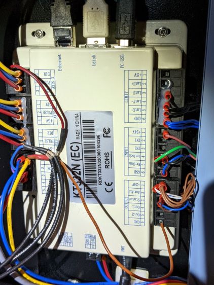
From top to bottom:
- X axis DIR: low = left-to-right motion = toward X+
- Laser L-ON: low-active laser beam enable
- PWM: pulse-width modulation laser power control
Those three cables pass through a small hole in the cabinet to the left of the hatch on their way to channels 1, 2, and 3 of the scope.
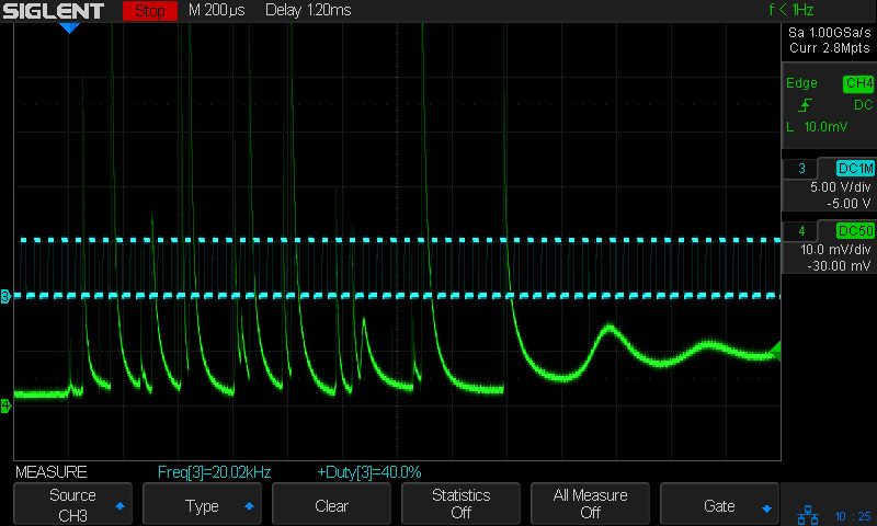
The PWM signal (cyan, channel 3) isn’t particularly useful, but a quick look confirmed it is an active-high signal ticking along at 20 kHz, with a duty cycle corresponding to the selected laser “power”:
The bottom trace (green, channel 4) is the laser tube current, as monitored by a Tek A6302 Hall-effect current probe around the tube’s cathode (low voltage return) lead:
This time around, I poked a bight of that overly long wire through the hole in the cabinet (just above the power-line earth ground terminal) so I could keep the probe outside the cabinet and close the hatch.
Minus the PWM signal, the scope looks like this:

The top trace (yellow, channel 1) is the DIR signal, with a high-to-low transition triggering the scope when the X axis begins moving from left to right.
The second trace (magenta, channel 2) is the L-ON laser enable; the high-voltage power supply drives current through the laser tube only when L-ON is low.
The third trace (green, channel 4) is, as above, the laser tube current. The Tek AM502 amplifier sets the gain, with the scope channel always set to 10 mV/div with a 50 Ω input impedance, so I must put the current scale in the screenshot file name (which becomes the caption here).
With all that in mind, the next few posts will make more sense … and I can remember what I did.

Comments
6 responses to “CO₂ Laser Tube Current: Test Wiring”
[…] Yesterday’s post explains the test wiring setup and the signals in the scope screenshots. […]
[…] signals and traces arranged as before, the beam current shows the same huge spikes during the 10% and 20% PWM bars and at the start of […]
[…] mm on a side and the pattern runs at 250 mm/s, so the laser will be enabled for 4 ms. For example, the test setup shows the result of a pass at 50% […]
[…] test patterns were engraved at various power levels, which was the whole point of the exercise: I was looking at the current waveforms, rather than the acrylic. Despite that, the result should […]
[…] a thousand opinions, I recorded the power supply output current as a function of PWM frequency. The test setup is the same as for the original series of current measurements, with oscilloscope traces arranged […]
[…] blue and purple wires go off to the oscilloscope I’ve been using to measure how the controller and power supply […]