Ed Nisley's Blog: Shop notes, electronics, firmware, machinery, 3D printing, laser cuttery, and curiosities. Contents: 100% human thinking, 0% AI slop.
The Mesa Electronics 5I25 FPGA card can implement a vast number of hardware I/O controllers, but I’ve only set up the few Kicad symbols required for my simple Sherline mill. The LinuxCNC hostmot2 doc gives the details.
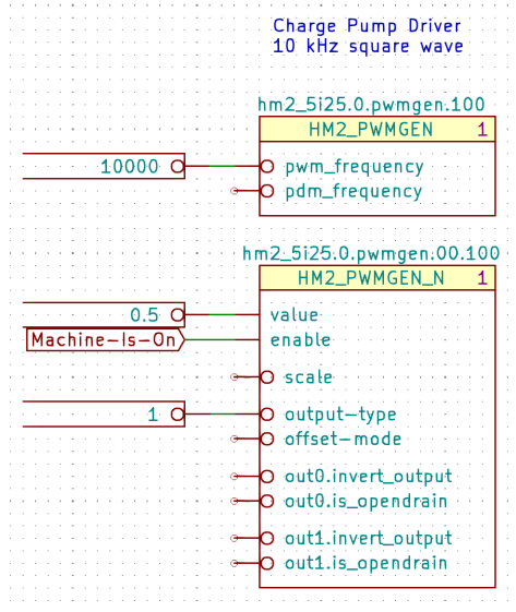
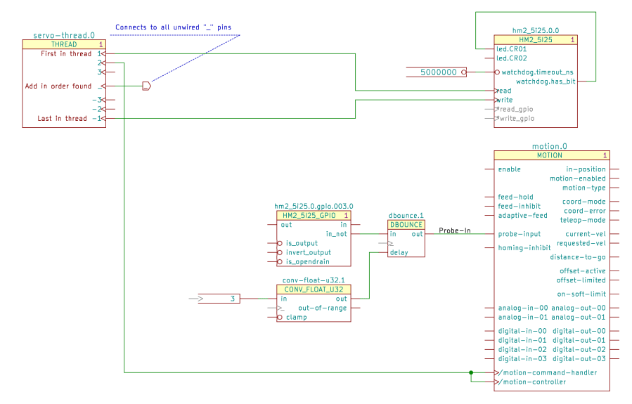
The hm2_5i25.0 component (upper right) carries the pins and functions pertaining to the card itself:
Servo Thread Hookup schematic
If you have two such cards, you’ll also have an hm2_5i25.1 component. Kicad will annotate both with a zero, which Kicad-to-HAL then strips off before attaching the pin names.
The read and write functions must attach to the first and last positions of the servo-thread component, respectively, to make the thing work correctly.
The read_gpio and write_gpio functions are normally not connected; the * prefix suppresses a Kicad-to-HAL message about unconnected named pins. The code will strip the asterisk before connecting the pins, but that part is … lightly tested.
Similarly, the schematic shows the watchdog output connected to one of the on-card LEDs. I’m not sure how to test that and wouldn’t see it inside the PC case; it might work as described.
A hm2_5i25.0.gpio.000 Kicad symbol (middle) collects all of the HAL pins related to a single 5I25 GPIO pin; edit the three-digit pin identifier to match the hardware pin. Although the out and in names look backwards, they indicate the hardware direction: you write to the out pin and read from the in pin.
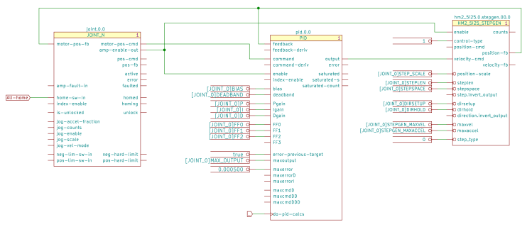
The Sherline uses four stepgen blocks, so that’s the only other Kicad symbol on offer:
X Axis Joint PID Stepgen schematic
The nets connecting those three components come directly from the LinuxCNC pncconf configuration utility. Fancier machines surely require more attention to the coefficient details.
Connecting a true parameter to the step.invert_output and direction.invert_output pins flips the polarity of those signals. The pins are aliases of the corresponding GPIO invert_output pin, with the key advantage of not requiring you to figure out which GPIO pin corresponds to the FPGA’s output pin for each axis.
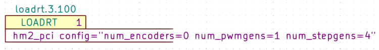
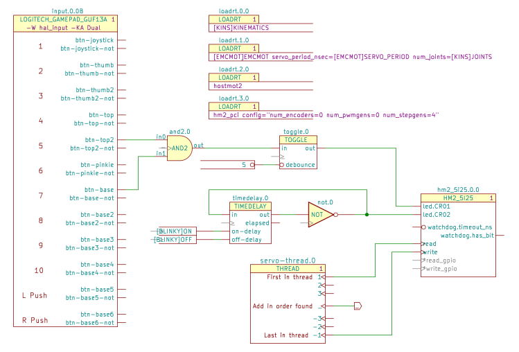
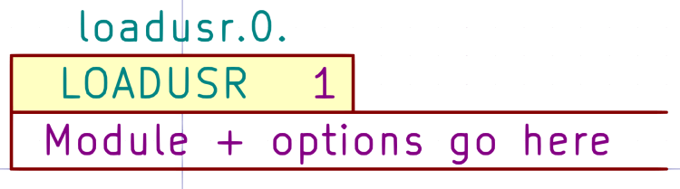
The 5I25 card requires a pair of loadrt components to load the drivers and configure the FPGA:
Kicad-to-HAL Demo Schematic
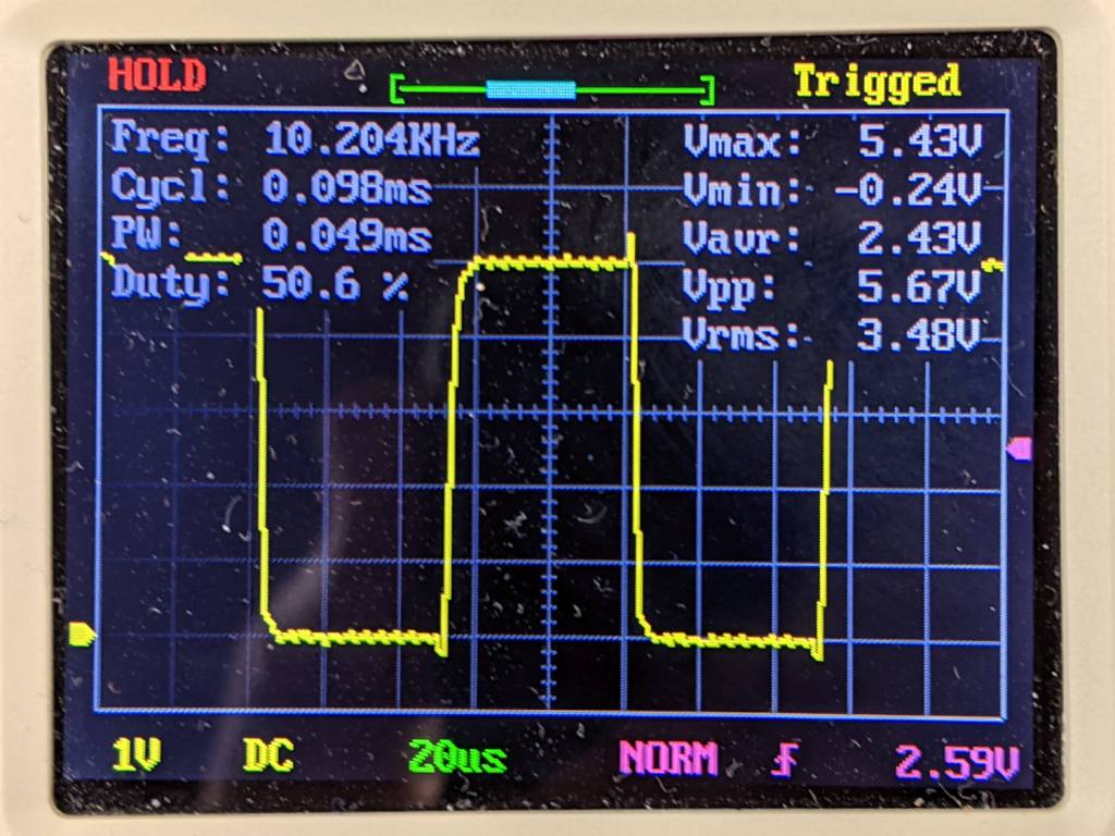
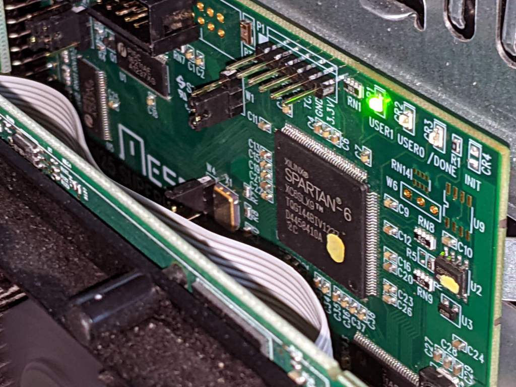
The one-page demo schematic uses the same 5I25 configuration as the Sherline, with the LEDs driven by gamepad buttons to provide something to look at:
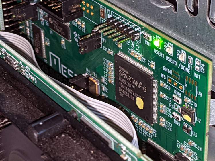
Mesa 5I25 card – LED activity
I should force-fit an LED into the Sherline driver box just to have something easier to see.
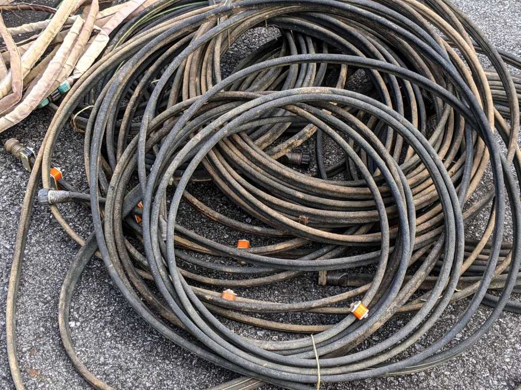
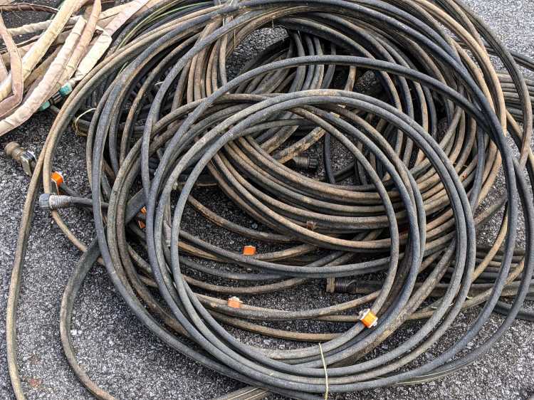
In the unlikely event I ever give another in-person presentation about 3D printing and what it’s good for, I’ll have some interesting show-n-tell samples. Might have to soak the dirt off, though.
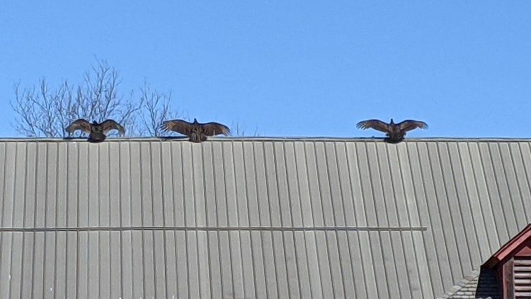
Spotted after pre-season prep at Mary’s Vassar Farms garden:
Vultures sunning
It must feel really good up there atop the old barn, even if they’re sunning themselves to kill off parasites.
Taken with the Pixel 3a zoomed all the way in at 7× from a bit over 200 feet:
Vultures sunning – photo range
Then cropped and sharpened just a smidge. Not a great picture, but good enough for practical purposes; the Good Camera + Big Glass takes better pix and is too awkward to carry in my pocket.
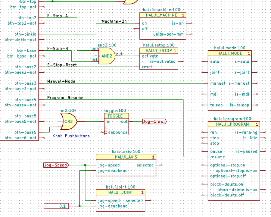
The Kicad references (halui.mode.100) use periods as separators, not dashes, because HALUI runs automagically and has no thread functions.
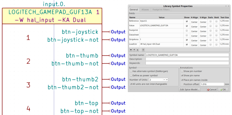
The symbol name (HALUI_MODE) serves as a unique identifier that should match the reference stem. I used underscores just for pretty, but it doesn’t make any difference.
All of the Kicad symbols include the StripAnno field to remove the Kicad annotation, as described earlier. The Kicad annotations now start from 100, because I’m in the midst of tinkering an automagic way to produce the proper start-from-zero HAL numbering with everything properly sorted; this is very much a work in progress.
So the full name of the resume pin on the HALUI_PROGRAM component sporting Kicad reference halui.program.100 is just:
halui.program.resume
This corresponds to the description of that pin in the HALUI doc, without a numeric identifier: there is only one HALUI.
The net connecting the gamepad button to that pin:
net _Gamepad_Buttons_Program-Resume <= input.0.btn-base4 => halui.program.resume
A few more examples from the nets near the AND2 gate:
net _Gamepad_Buttons_E-Stop-A <= input.0.btn-top2 => and2.0.in0
net _Gamepad_Buttons_E-Stop-B <= input.0.btn-base => and2.0.in1
net _Gamepad_Buttons_E-Stop-Reset <= input.0.btn-base2 => halui.estop.reset
net _Gamepad_Buttons_Machine-On <= input.0.btn-pinkie => halui.machine.on
net _Gamepad_Buttons_Manual-Mode <= input.0.btn-base3 => halui.mode.manual
Some HALUI component references include numbers and letters identifying specific joints / axes / spindles, all of which you must edit as needed and none of which should be subjected to Kicad’s renumbering whims:
X Axis jogging schematic
The HAL commands producing the nets connecting the AND2 gates to the HALUI pins:
net N_065 <= and2.14.out => halui.axis.x.minus halui.joint.0.minus
net N_066 <= and2.15.out => halui.axis.x.plus halui.joint.0.plus
The nets lack any specific name, so Kicad-to-HAL replaces Kicad’s default gibberish with the next integer from an ascending series. If your HAL configuration requires more than three digits worth of anonymous nets, feel free to tweak the format string.