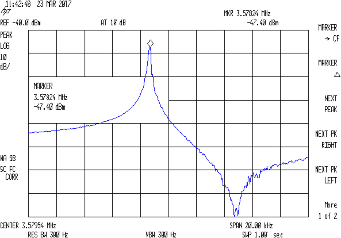
Just to see if the resonator test fixture produced meaningful results, I plugged a 3.57954 MHz color burst crystal into the socket:

This is a staged recreation based on actual events; pay no attention to the Colpitts oscillators growing in the background.
Attaching goesinta and goesouta cables to the HP 8591 spectrum analyzer & tracking generator showed it worked just fine:
The reference level is -40 dBm, not the usual 0 dBm, due to the loss in those resistive pads. Unsurprisingly, the parallel resonance valley looks pretty ragged at -120 dBm = 1 nW = 7 µV.
Remove the jumper to put the capacitor in series:
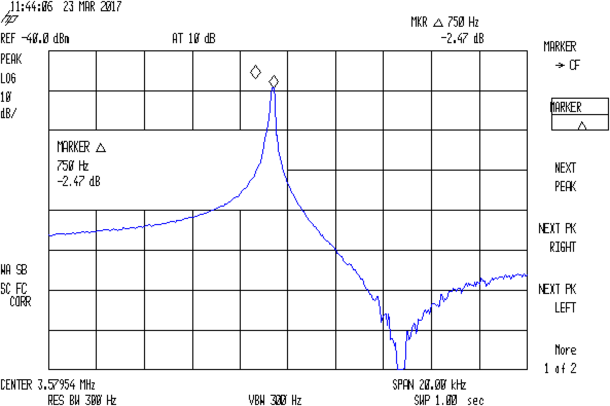
The marker delta resolution surely isn’t 1 Hz, but 750 Hz should get us in the right ballpark.
Substituting a 72 Ω resistor, found by binary search rather than twiddling a pot:
Which gives us all the measurements:
- Fs = 3.57824 MHz
- Fc = Fs + 750 Hz = 3.57899 MHz
- Rm = 72 Ω
- C0 = 3.83 pF
- Cpar = 3.70 pF
Turn the crank and the crystal motional parameters pop out:
- Lm = 117 mH
- Cm = 17 fF
- Rm = 72 Ω
- Q = 36 k
Looks like a pretty good crystal to me!

Comments
2 responses to “Quartz Resonator Test Fixture: 3.58 MHz Crystal Test”
I assume you measured the capacitances with the other fixture? Interestingly, I’m building a Colpitts oscillator too: I had seen an example circuit (for a theremin) that used a Hartley oscillator, but I didn’t have any tapped inductors of the right values, so I rearranged the circuit into a Colpitts configuration, as it was easy to find two capacitors of appropriate values in my junk pile. Musing on it, I realized that it makes AC ground (as seen by the active element) the junction of the capacitors, magically providing an inverted signal from the bottom capacitor.
Yup!
Even a Darlington NPN with megohm biasing loads a 32 kHz tuning fork too much: it won’t start reliably. Works better at 60 kHz, so maybe I just ignore the problem & move on.