An undrilled double-sided circuit board with the edges bonded together doesn’t look like much:
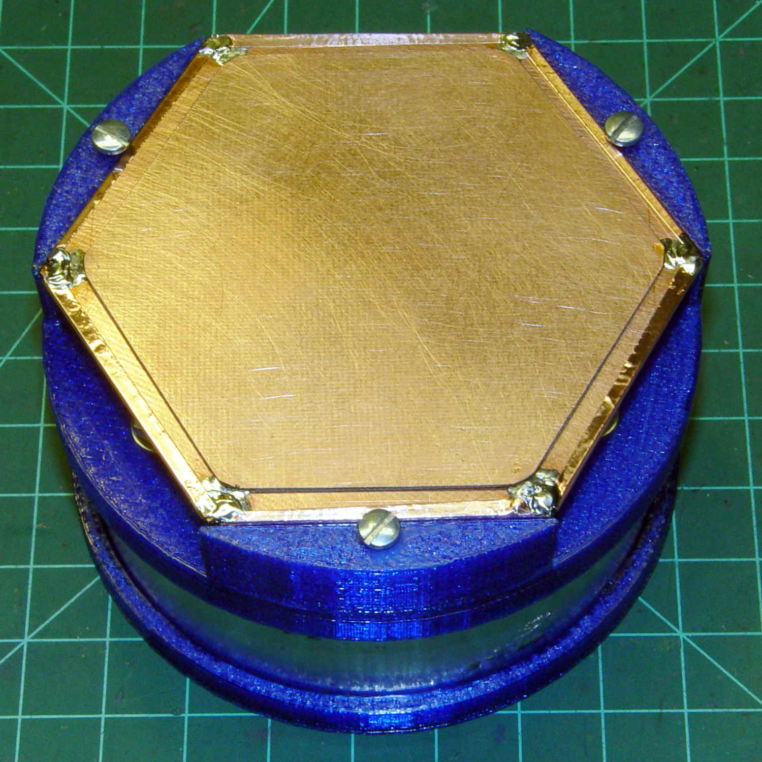
Soldering a smaller hex to the center of the bonded plate produces an isolated plane:
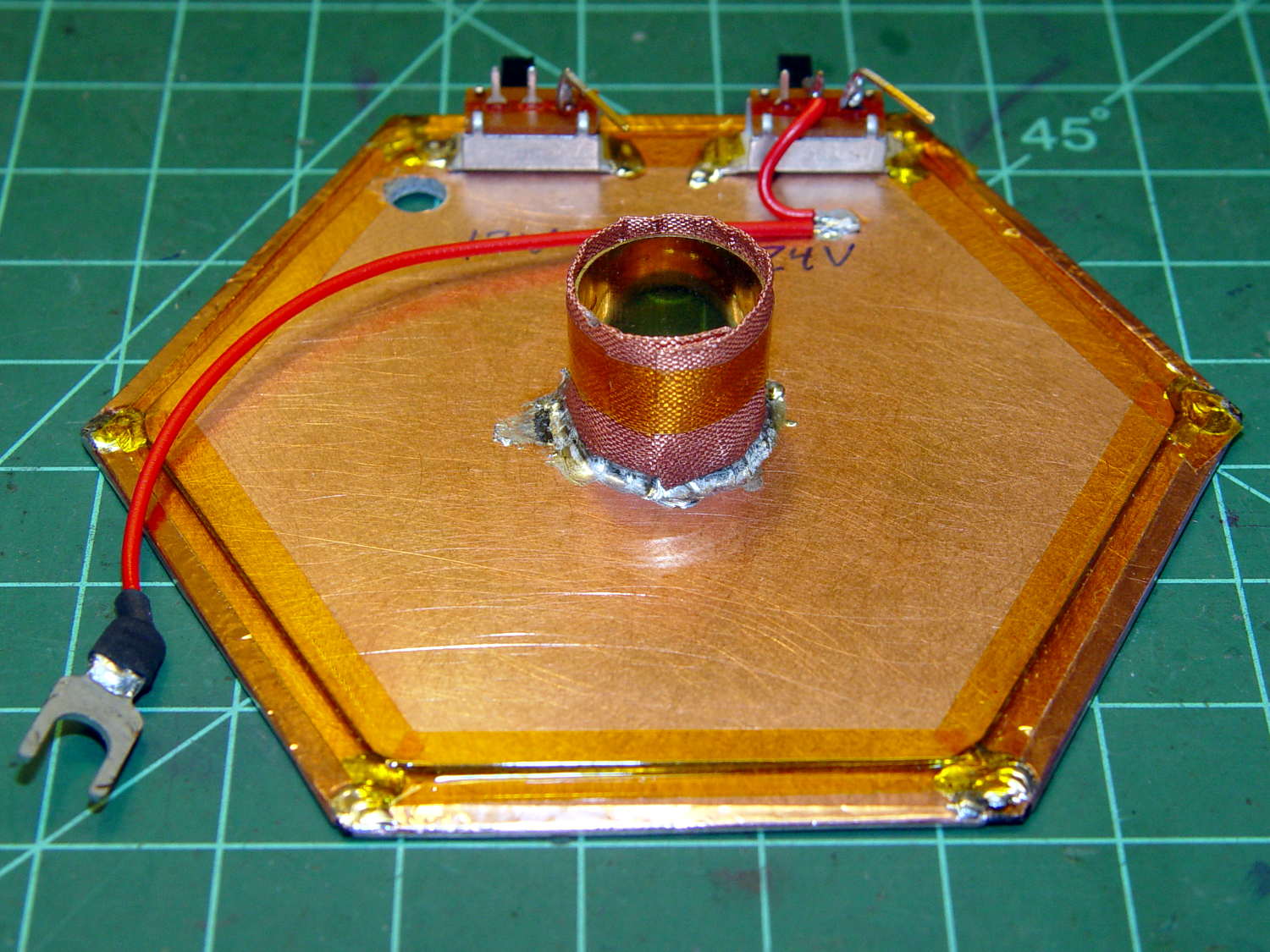
The copper fabric tape wrapped around a brass tube soldered to the isolated plane contacts the ionization chamber shell around the central contact and (should) provide complete shielding. Kapton tape around the edges reduces the likelihood of inadvertent shorts.
Working with a shield at +24 V gave me the shakes, so this one confines the chamber bias to the isolated hex and shell, with the larger hex at circuit common (a.k.a. ground). The isolated plane has about 275 pF to the ground plane, which isn’t a Bad Thing at all. In principle, the chamber bias doesn’t need a switch, because there’s no current drain, but I vastly prefer having cold circuitry before popping the lid.
If I had a small DPST switch, I’d use it:
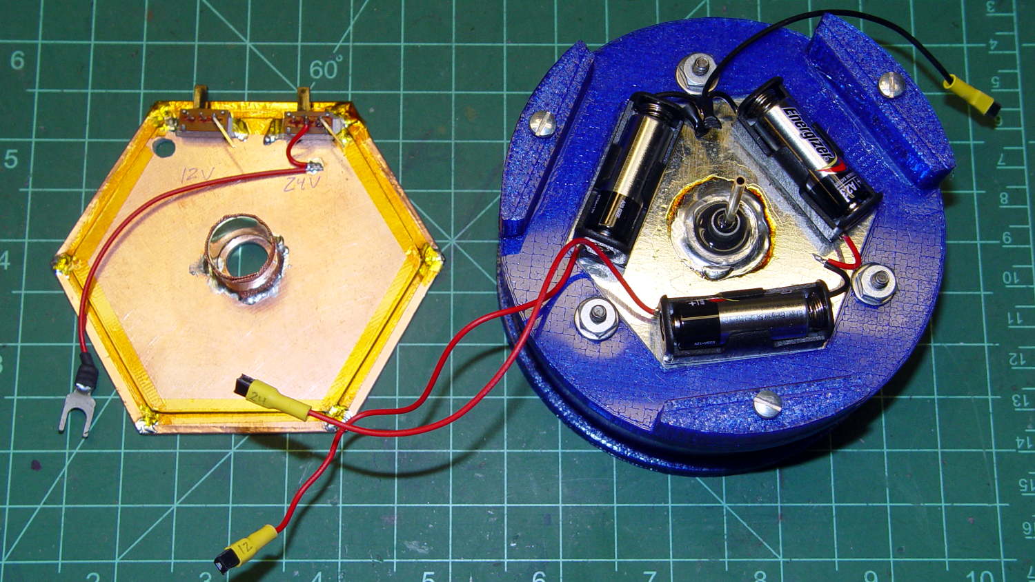
As it stands, one switch controls the +24 V chamber bias and the other switches +12 V power to the electrometer amp front end, with simpleminded connectors so I can separate the pieces.
We’ll see how well all that works in practice.
An alert reader will notice the tiny difference between the blue PETG shapes in the two pictures. The bottom one comes from the revised code, of course.
