Ed Nisley's Blog: Shop notes, electronics, firmware, machinery, 3D printing, laser cuttery, and curiosities. Contents: 100% human thinking, 0% AI slop.
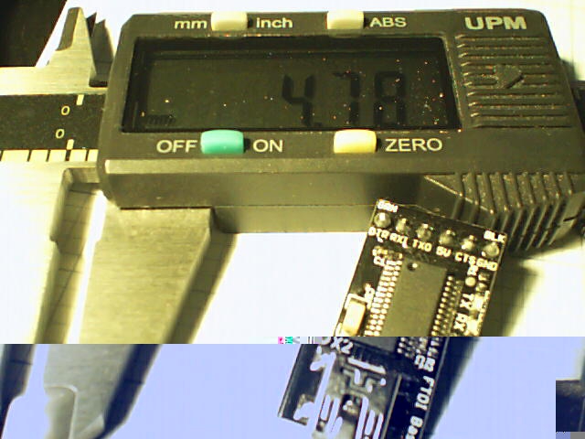
Having run off four quick prints with identical settings, I measured the thickness of the skirt threads around each object:
Skirt Thread Consistency
They’re all slightly thicker than the nominal 0.25 mm layer thickness, but centered within ±0.02 mm of the average 0.27 mm. Tweaking the G92 offset in the startup G-Code by 0.02 would fix that.
The 0.29 mm skirt surrounded the first object, which had a truly cold start: 14 °C ambient in the Basement Laboratory. After that, they’re pretty much identical.
Some informal measurements over a few days suggests the actual repeatability might be ±0.05 mm, which is Good Enough for layers around 0.20 to 0.25 mm.
The larger skirt suggests that the platform has a slight tilt, but the caliper resolution is only 0.01 mm.
When I realigned everything after installing the V4 hot end, the last set of thinwall boxes looked like this:
This is mostly a test to see how long it takes before something on the RPi goes toes-up enough to require a manual reboot. Disabling the WiFi link’s power saving mode seems to keep the RPi on the air all the time, which is a start.
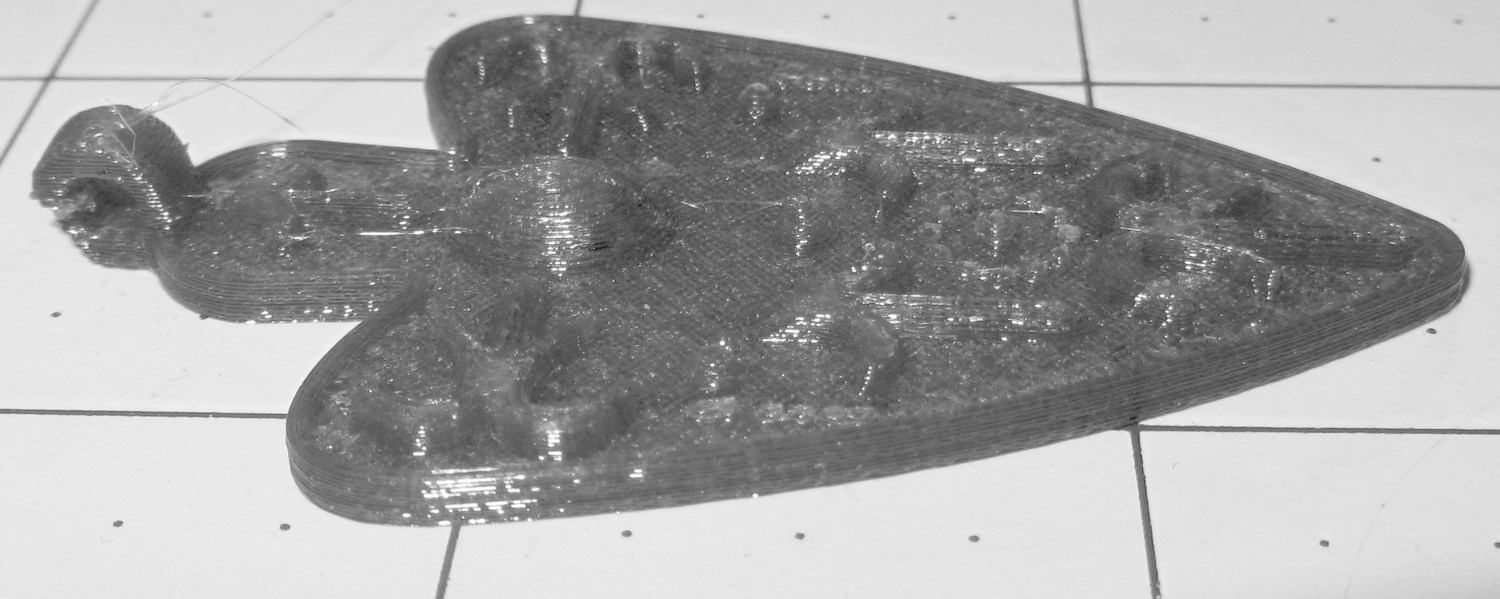
I also tried using the camera in its B&W mode to discard the color information up front:
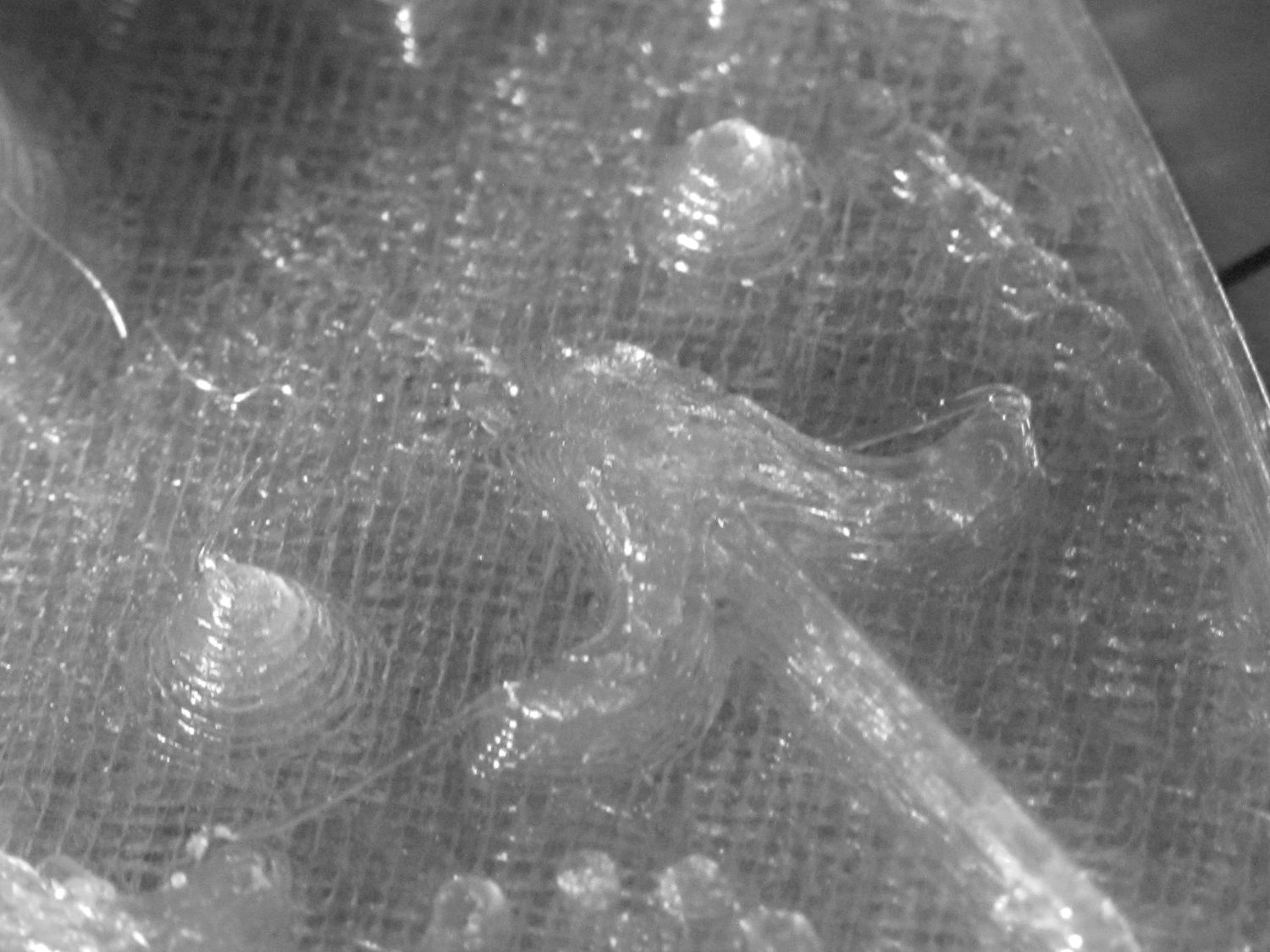
Necklace Heart – circle detail
It’s taken through the macro adapter with the LEDs turned off and obviously benefits from better lighting, with an LED flashlight at grazing incidence. You can even see the Hilbert Curve top infill.
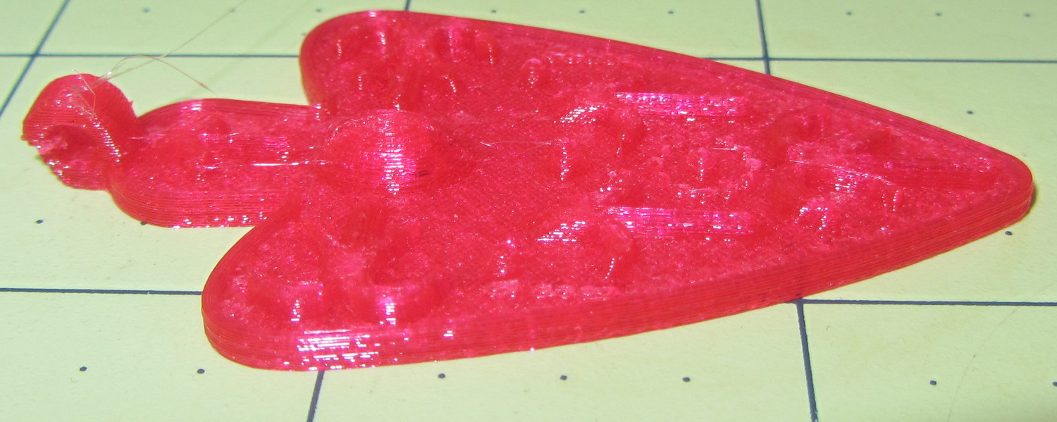
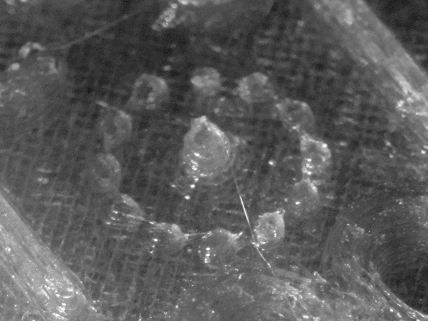
The object of the exercise was to see if those tiny dots would print properly, which they did:
Necklace Heart – dots detail
Now, admittedly, PETG still produces fine hairs, but those dots consist of two layers and two thread widths, so it’s a harsh retraction test.
A look at the other side:
Necklace Heart – detail
All in all, both the object and the pix worked out much better than I expected.
Leaving the camera in full color mode and processing the images in The GIMP means less fiddling with the camera settings, which seems like a net win.
Combining the camera data I collected a while ago with a few hours of screwing around with this old Logitech camera:
Logitech QuickCam for Notebook Plus – front
I’m convinced it’s the worst camera I’d be willing to use in any practical application.
The camera offers these controls:
fswebcam --list-controls
--- Opening /dev/video0...
Trying source module v4l2...
/dev/video0 opened.
No input was specified, using the first.
Available Controls Current Value Range
------------------ ------------- -----
Brightness 128 (50%) 0 - 255
Contrast 128 (50%) 0 - 255
Gamma 4 1 - 6
Exposure 2343 (8%) 781 - 18750
Gain, Automatic True True | False
Power Line Frequency Disabled Disabled | 50 Hz | 60 Hz
Sharpness 2 0 - 3
Adjusting resolution from 384x288 to 320x240.
Putting the non-changing setup data into a fswebcam configuration file:
cat ~/.config/fswebcam.conf
# Logitech QuickCam for Notebook Plus -- 046d:08d8
device v4l2:/dev/video0
input gspca_zc3xx
resolution 320x240
scale 640x480
set sharpness=1
#jpeg 95
set "power line frequency"="60 hz"
Trying to use 640×480 generally produces a Corrupt JPEG data: premature end of data segment error, which looks no better than this and generally much worse:
Logtech 08d8 – 640×480
The top of the picture looks pretty good, with great detail on those dust particles, but at some point the data transfer coughs and wrecks the rest of the image. I could crop the top half to the hipster 16:9 format of 640×360, but the transfer doesn’t always fail that far down the image.
The -R flag that specifies using direct reads instead of mmap, whatever that means, doesn’t help. In fact, the camera generally crashes hard enough to require a power cycle.
Delaying a second with -D1 and / or skipping a frame with -S1 don’t help, either.
The camera works perfectly at 640×480 using fswebcam under Xubuntu 14.04 on a Dell Latitude E6410 laptop, so I’m pretty sure this is a case of the Raspberry Pi being a bit underpowered for the job / the ARM driver taking too long / something totally obscure. A random comment somewhere observed that switching from Raspbian to Arch Linux (the ARM version) solved a similar video camera problem, so there’s surely room for improvement.
Dragorn of Kismet reports that the Raspberry Pi USB hardware doesn’t actually support USB 2.0 data rates, which also produces problems with Ethernet throughput. The comments in that slashdot thread provide enough details: the boat has many holes and it’s not a software problem.
For lack of anything more adventurous, the config file takes a 320×240 image and scales it up to 640×480, which looks about as crappy as you’d expect:
Logtech 08d8 – 320×240 scaled
Even that low resolution will occasionally drop a few bytes along the way, but much less often.
The picture seems a bit blown out, so set the exposure to the absolute minimum:
Given that’s happening a foot under a desk lamp aimed well away from the scene, the other end of the exposure scale around 18000 produces a uselessly burned out image. I think a husky neutral-density filter would be in order for use with my M2’s under-gantry LED panels. The camera seems to be an early design targeting the poorly illuminated Youtube / video chat market segment (I love it when I can talk like that).
There’s probably a quick-and-dirty Imagemagick color correction technique, although Fred’s full-blown autocorrection scripts seem much too heavy-handed for a Raspberry Pi…
First up: it’s not our projector, which means the usual Rules of Engagement do not apply.
A few small black plastic fragments fell out of the Epson S5 projector’s carry bag, the front foot wouldn’t remain extended, and, as one might expect, the two incidents were related. Mary needed it for the gardening class she was teaching the next evening, sooooo…
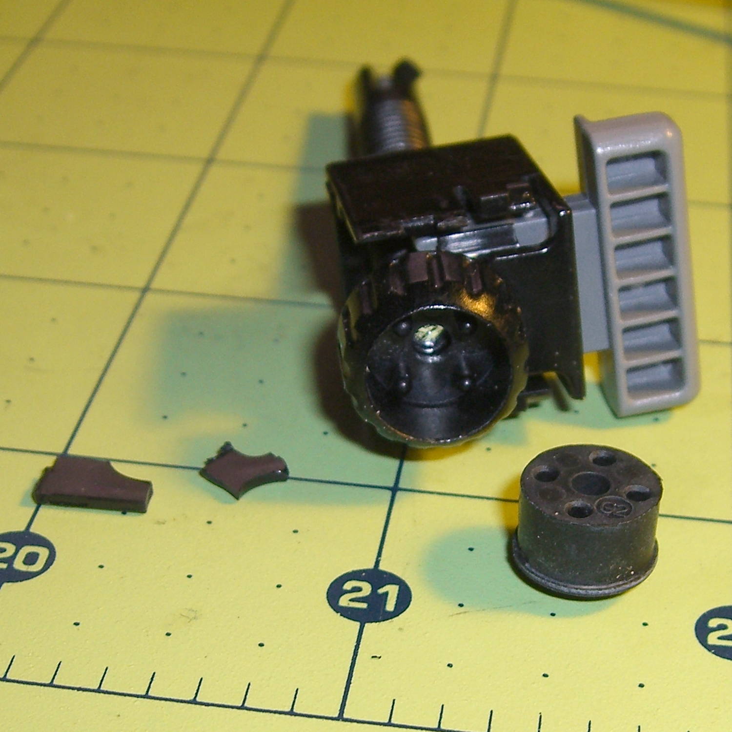
A pair of plastic snaps release the entire foot assembly from the front of the projector:
Epson S5 Projector Foot – assembled
It became obvious that we didn’t have all the fragments, but it was also obvious that, even if we had the pieces, a glued assembly wouldn’t last very long.
The threaded plastic stem surrounds a steel pin that’s visible when you remove the rubber foot pad. That pin holds the latch on the end of the stem outward, so that the stem can’t fall out. Drive out the pin with a (wait for it) pin punch inserted from the foot pad end, which reveals the broken plastic doodad:
Epson S5 Projector Foot – stem removed
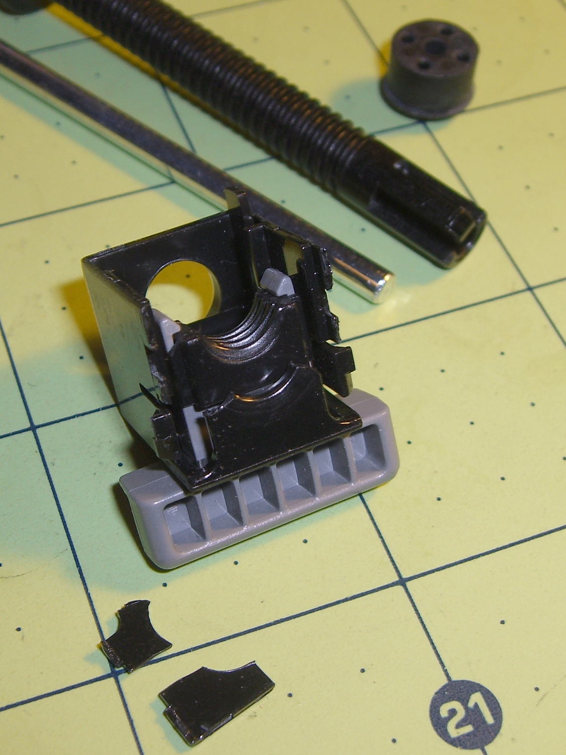
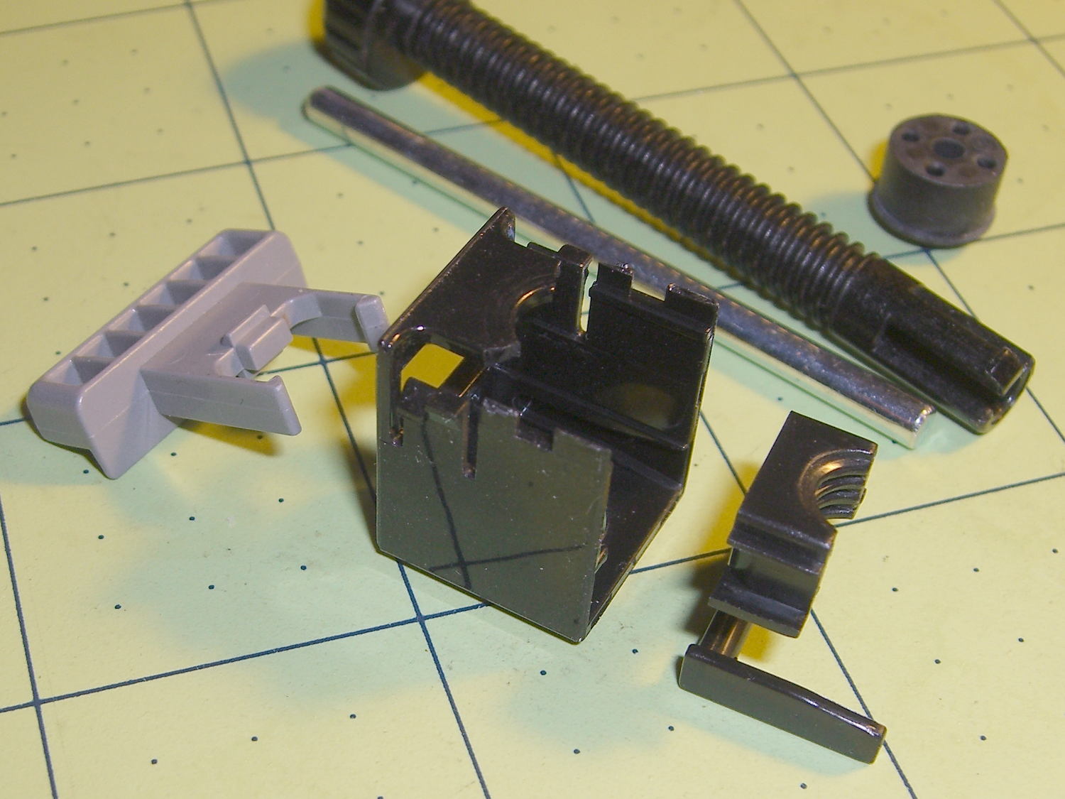
Release the latches on the gray handle and the intricate half-nut that engages the threaded stem slides out:
Epson S5 Projector Foot – disassembled
A plastic spring in the boxy shell pushes the gray handle and half-nut against the stem, holding the stem in place. Pushing the gray handle upward (on the projector, downward in the picture, yes, your fingertip can feel those ribs just fine) pulls the half-nut away from the stem and lets the stem slide freely. With the stem extended, the projector leans on the stem, pushes it against the half-nut, and you can fine-tune the angle by turning the stem; the splines around the rubber foot encourage that. You can pull the stem outward without activating the latch, which probably broke the fragile plastic plate.
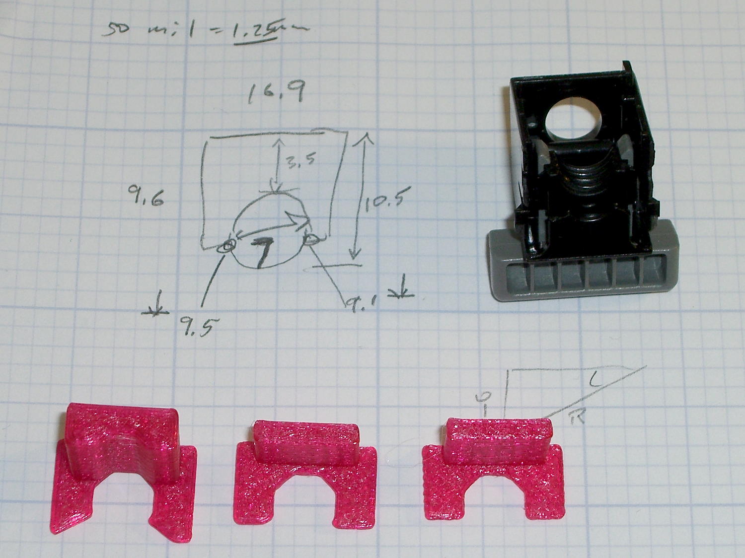
A doodle showing the estimated measurements, plus three 3D printed prototypes required to get a good fit:
Epson S5 Projector Foot – measurements and versions
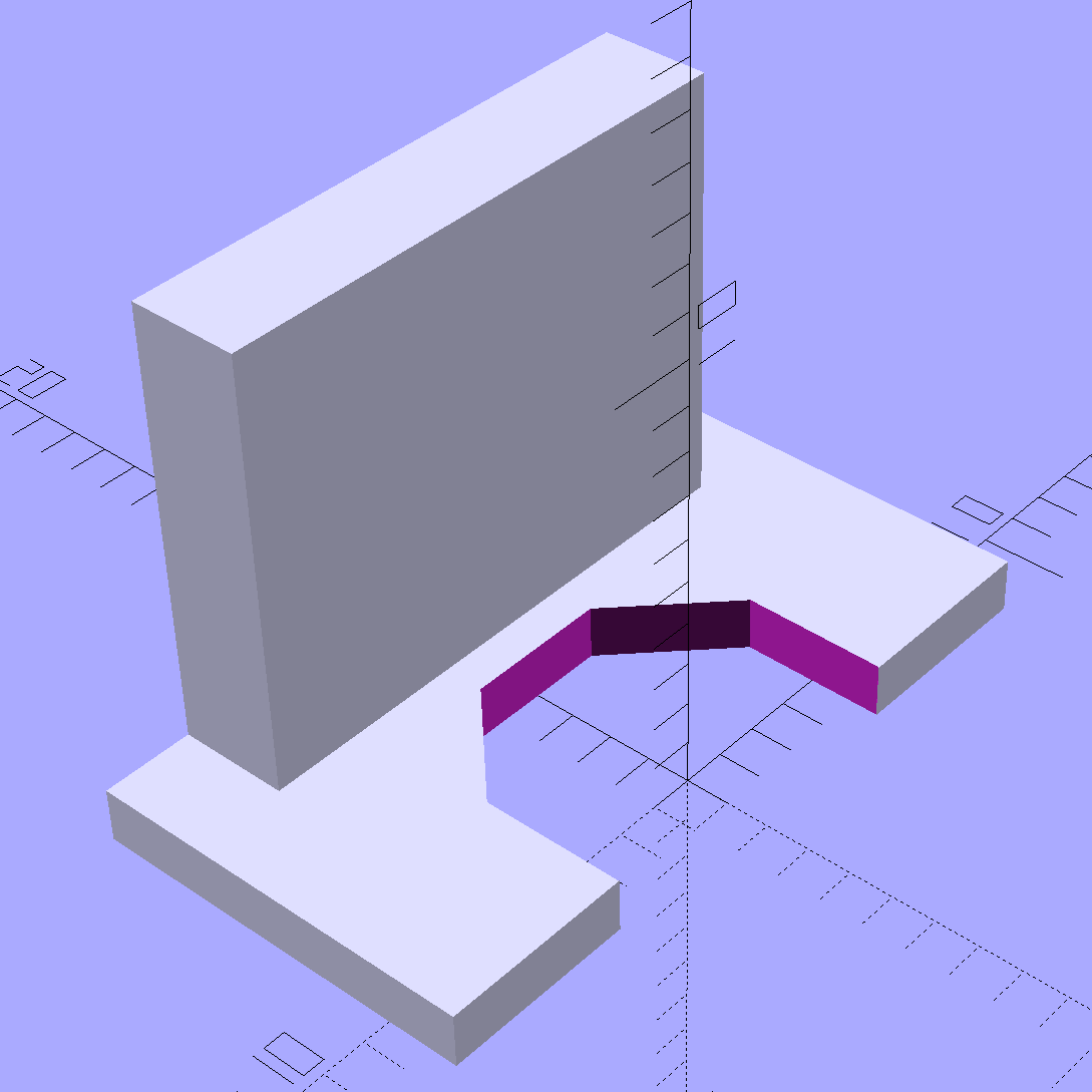
The solid model looks about like you’d expect:
Epson S5 Projector foot latch – solid model
The first version (leftmost of the three sitting on the doodle, above) had angled ends on the tabs that I intended to match up with the stubs remaining on the OEM latch. The part fit better with shorter tabs and the angles vanished on third version; the statements remain in the OpenSCAD source, but the short tabs render them moot.
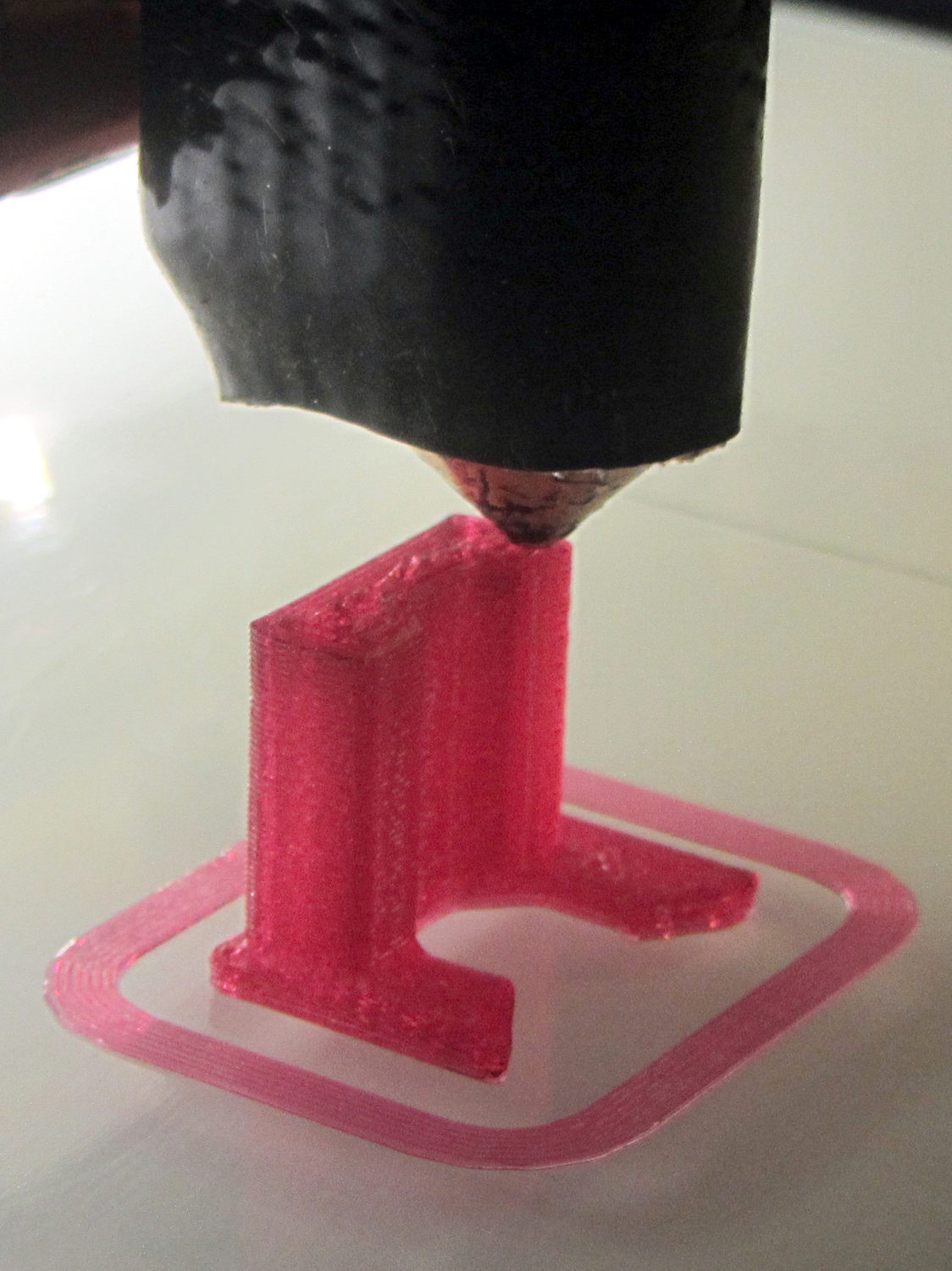
Apparently I got the cooling & fan & minimum layer time pretty close to right for PETG, as each of those three towers printed singly with no slumping:
Epson S5 Projector Foot – V1 on platform
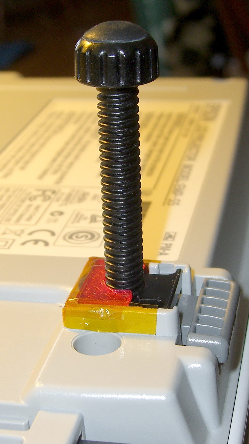
The third version snapped into place, with a square of tapeless sticky on the back to help keep it there. The obligatory Kapton tape helps retain it, but I have no illusions about the permanence of this repair:
Epson S5 Projector Foot – repair installed
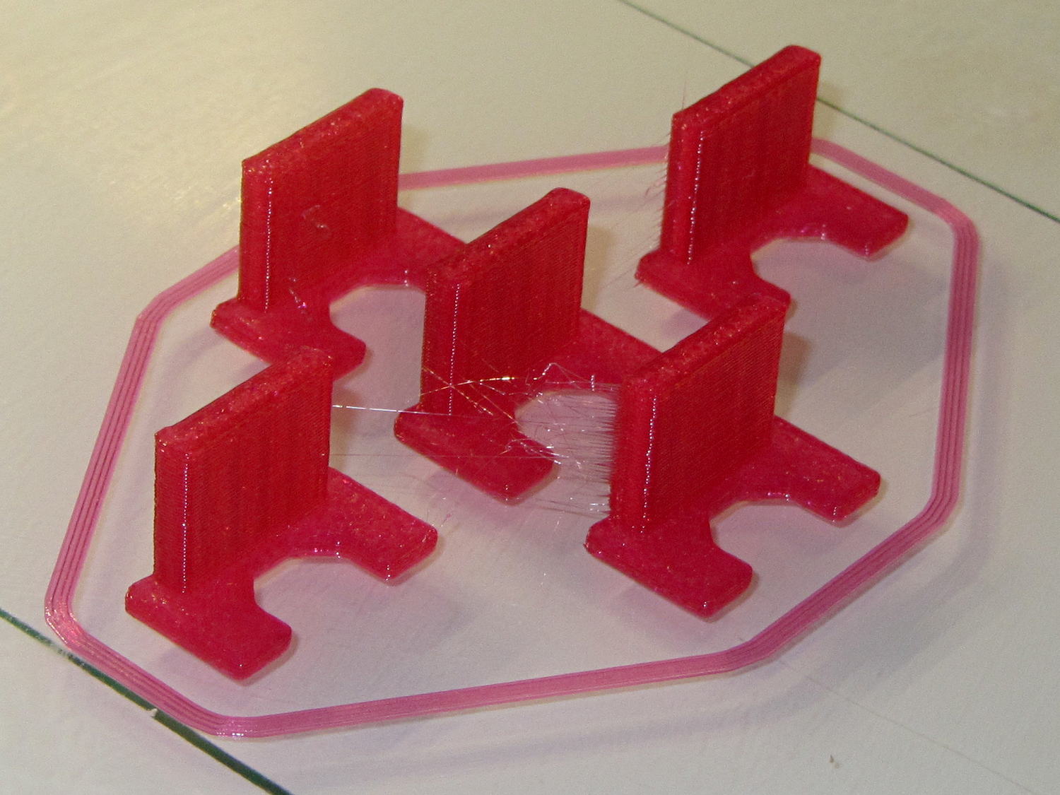
Because I know the problem will happen again, I called for backup:
Epson S5 Projector Foot – 5 copies
That’s with Hilbert Curve top / bottom fill, three top / bottom layers, 20% rectilinear infill, and two perimeters. Extruder at 250 °C, platform at 90 °C, hairspray for adhesion.
Note, however, the hair-fine strings connecting the towers. Retraction must be just about right, as shown by the overall quality of the objects, but PETG comes out really stringy. Choosing an infill pattern to minimize retraction seems like a big win; relatively sparse 3D Honeycomb works well on larger objects, but these were so small that straight line fill fit better. The flat plates on the bottom consist of five completely solid layers of PETG.
Reports from the field indicate complete success: whew!
One could, of course, just buy a replacement from the usual eBay supplier, if one were so inclined.