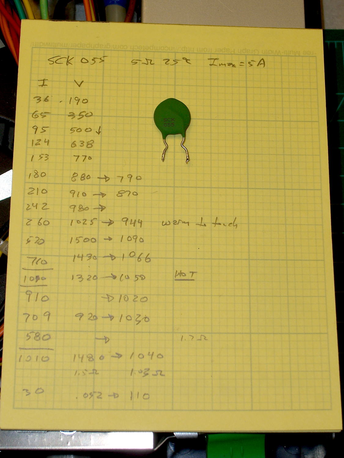
While pondering the dead ET227 transistors, I dug an inrush current limiter (a.k.a. NTC power thermistor) out of the heap and made some measurements:
That’s from a bench power supply attached to a meter and the limiter with clip leads, which was entirely too messy for a picture.
Turning those numbers into a spreadsheet to calculate the resistances:
| SCK 055 NTC Power Thermistor | ||||
| 5 Ω @ 25 °C | ||||
| Imax = 5 A | ||||
| Time constant on the order of 90 seconds | ||||
| Current mA | Initial mV | Final mV | Initial Ω | Final Ω |
| 36 | 190 | 5.3 | ||
| 65 | 350 | 5.4 | ||
| 95 | 500 | 5.3 | ||
| 124 | 638 | 5.1 | ||
| 153 | 770 | 5.0 | ||
| 180 | 880 | 790 | 4.9 | 4.4 |
| 210 | 910 | 870 | 4.3 | 4.1 |
| 242 | 980 | 4.0 | ||
| 260 | 1025 | 944 | 3.9 | 3.6 |
| 520 | 1500 | 1090 | 2.9 | 2.1 |
| 710 | 1430 | 1066 | 2.0 | 1.5 |
| 1010 | 1320 | 1050 | 1.3 | 1.0 |
| 910 | 1020 | 1.1 | ||
| 709 | 920 | 1030 | 1.3 | 1.5 |
| 1010 | 1480 | 1040 | 1.5 | 1.0 |
| 30 | 52 | 110 | 1.7 | 3.7 |
The data sheet recommends a minimum current above 30% of the maximum, which would be 1.5 A. That’s above the motor’s 1 A operating current, let alone the low-speed current limited conditions, but in this situation that just means the resistance will remain around 1 to 2 Ω with the motor chugging along.
If I had more of ’em, I could put them in series to build up the resistance, but it’s not clear why that would be better than, say, a 6 Ω aluminum-heatsink resistor dissipating a few watts.
