This arrangement actually worked:
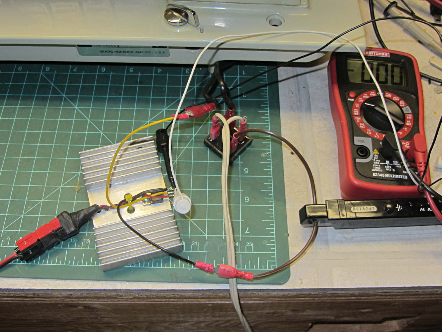
At least until I blew out the MOSFET, which is about what I expected. It’s screwed to that randomly selected heatsink, with a dab of thermal compound underneath.
Incoming AC from an isolated variable transformer (basically, an isolated Variac) goes to a bridge rectifier. Rectified output: positive to the motor, motor to MOSFET drain, MOSFET source to negative.
MOSFET gate from bench supply positive and supply negative to source.
Hall effect current probe clamped around the motor current path.
The MOSFET was an IRF610: 200 V / 3.3 A. That’s under-rated for what I was doing, but I had a bunch of ’em.
I actually worked up to that mess, starting with the bare motor on the bench running from the 50 VDC supply. That sufficed to show that you can, in fact, control the motor speed by twiddling the gate voltage to regulate the current going into the motor. It also showed that a universal-wound motor’s square-law positive feedback loop will definitely require careful tuning; think of an unstable fly-by-wire airplane and you’ve got the general idea.
In any event, flushed with success, I ignored the safe operating area graph (from the Vishay datasheet):
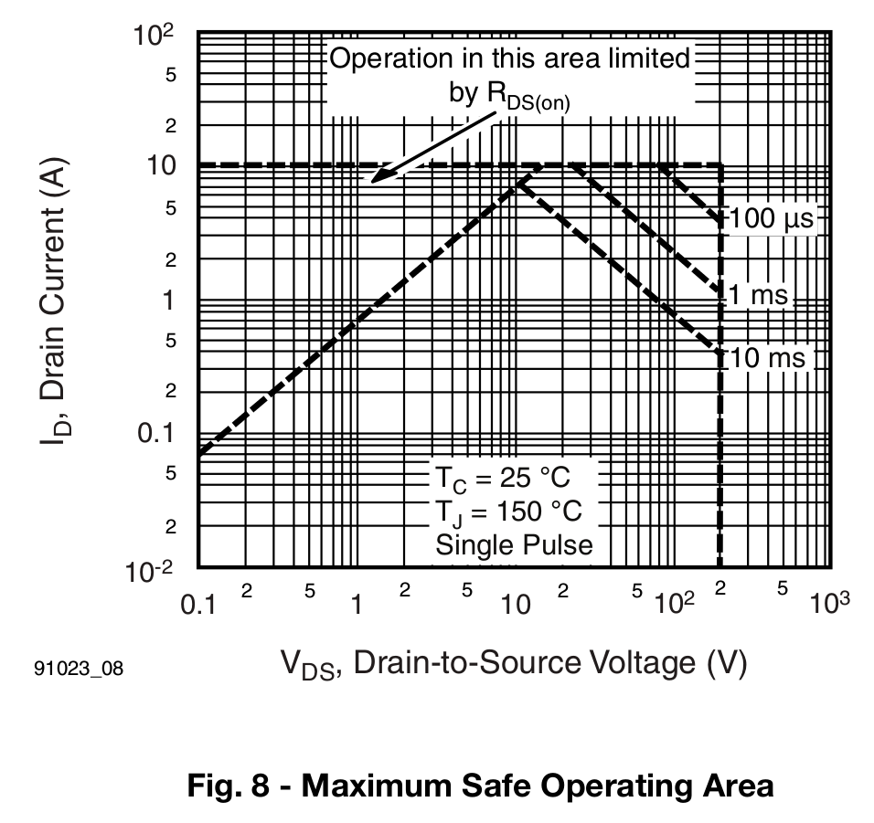
Drain current over half an amp at 160-ish peak volts (from rectified 120 VAC) will kill the MOSFET unless you apply it as short single pulses, not repetitive 120 Hz hammerblows.
I also ignored the transfer characteristics graph:

The curve starting at the lower left should be labeled 25 °C and the other should be 150 °C. The key point is that they cross around VGS = 6.5 V, where IDS = 2 A. Below that point, the MOSFET conducts more current as it heats up… which means that if a small part of the die heats up, it will conduct more current, heat up even more, and eventually burn through.
Yes, MOSFETs can suffer thermal runaway, too.
The motor draws about half an amp while driving the sewing machine, which suggests the gate voltage will be around 5 V. In round numbers, it was 5.5 to 6 V as I twiddled the knob to maintain a constant speed.
At half an amp, the MOSFET dissipated anywhere from a bit under 1 W (from RDS(on) = 1.5 Ω to well over 25 W (while trying to maintain headway with friction on the handwheel). I ran out of fingers to record the numbers, but dropping 10 to 20 V across the MOSFET seemed typical and that turns into 5 to 10 W.
It eventually failed shorted and the sewing machine revved up to full speed. Sic transit gloria mundi.
In any event, I think the only way to have a transistor survive that sort of abuse is to start with one so grossly over-rated that it can handle a few amps at 200 V without sweating. It might actually be easier to get an ordinary NPN transistor with such ratings; using a hockey puck IGBT or some such seems like overkill.
Eks probably has a box full of the things …

Comments
6 responses to “Kenmore 158: MOSFET vs. Rectified 120 VAC”
I’ve done a far cruder approach for a couple of 90VDC motors. One was a gear motor bought at the usual surplus shop, while the other had a motor controller until I slipped with the voltmeter probe [yikes]. (Too badly fried to try to fix the controller…)
I used a Home-Depot issue light dimmer (no recollection of the rating), ran it through a full-wave rectifier (and 5A breaker, being what I had in the heap) and to the motor. Haven’t used the gear motor much lately, but I’ve used it several hours in the past. The other motor has been used a couple of hours. No special treatment. Neither seems to have the torque at lower speeds that the dedicated controller gave, but that’s OK in my applications.
I’ve given a little thought to cribbing the design from the Sherline motor controller, but the need hasn’t applied yet. Still have another gear-motor in the heap, waiting for an application.
Dimmers shouldn’t work, but everybody swears by ’em. [grin]
I think the relatively low motor current doesn’t challenge the triacs very much, even though the winding inductance ought to stress ’em out.
Even if I’m gunshy of the noise from those high harmonics, I should try it out anyway…
Like most things in life, the greatest learning events happen when you destroy something. If there is smoke, flames, maybe even a good arc- it burns it into your memory. You read the data sheet, you knew that it would blow, you had already mentally prepared an calculated what would happen when it failed (runaway motor). The real science was the physical act of building the circuit to show it actually could operate and performed within all expectation, right until the point you began to load it and the failure. For me, I look at that as an enabler experiment. It shows that given a parts source and some reasonable expectations, someone can experiment and prove a theory. I think folks are so scared of blowing a part or failure, they simply never perform the experiment. I saw this same theme present during my late night engineering classes. The folks who blew up components learned lifelong lessons. The folks who never damaged even a resistor largely walked out of the class with little knowledge gained. The minimal cost of the parts involved is nothing compared to the real hands on knowledge gained. You saw first hand thermal runaway. You can talk about that in a classroom all day long, the young engineer ignores it. You make them build a circuit that will fail, have them watch it until the point of failure, it will make an impression. Again, the gut feeling is that you can succeed in electronics by blind luck. You learn little from that experience and may make a major mistake later on not understanding that was luck the previous time. If you bring something to destruction, you learn and remember how and why it failed, and hopefully never make that mistake again.
You move on to bigger and better mistakes!
Sometimes, you have no idea why something goes pfft, in which case it’s a detective story. In this case, I knew the operating point sat way over on the right and much too high up, making it just a matter of time until that poor transistor went toes-up.
As opposed to the NPN transistor we analyzed & plotted (by hand, with slide rules!) in Freshman Electronics a long, long time ago. After doing all the measurements, the lab instructor told us to burn it out. Except that we couldn’t, no matter what we did: it got hotter than the middle tailrace of Hell, but kept on being a transistor.
I should’a kept that as a memento!
Fond memories… In a semi-conductor processing class, we tried to make transistors. I have a pretty good idea of the few things we did right, but while the transistors didn’t trans, the diodes kind of worked. I lit one junction up, and was rewarded by the poor thing exploding. (There’s a zener-zap technique once used in tweaking many ICs, and watching that light show in a microscope is cool…)
The best explosions were the tunnel diode labs. You had a heater block and the open-bottomed “bell jar” was flooded with H2. Murphy had a field day, and there were a few folks with a rather dazed look after making water the hard way. (My tunnel diode actually worked.)
The most fun points in my career include the times we got to do some real science. You can do some really odd things with semiconductors and the related goodies…
FWIW, the Leviton dimmers seem to run about 300W. I should probably 1) change to a 2A breaker on one, and 2) do a better controller for the other. My hearing is medium-awful, so no hints on noise.
Yeah Doc Smith!
Everybody thought those things would be wonderful. Life lesson: components require three terminals to become an amplifier.