Fancy new sewing machines can stop with the needle either up (so you can remove the fabric) or down (to nail it in place while you rotate it). This requires sensing the needle position, which prompted me to spend far too long contemplating all the mechanical gadgetry driven by the motor.
As nearly as I can tell, the crank counterweight behind the handwheel produces the most unambiguous position reports. Here’s what it looks like with the needle down:
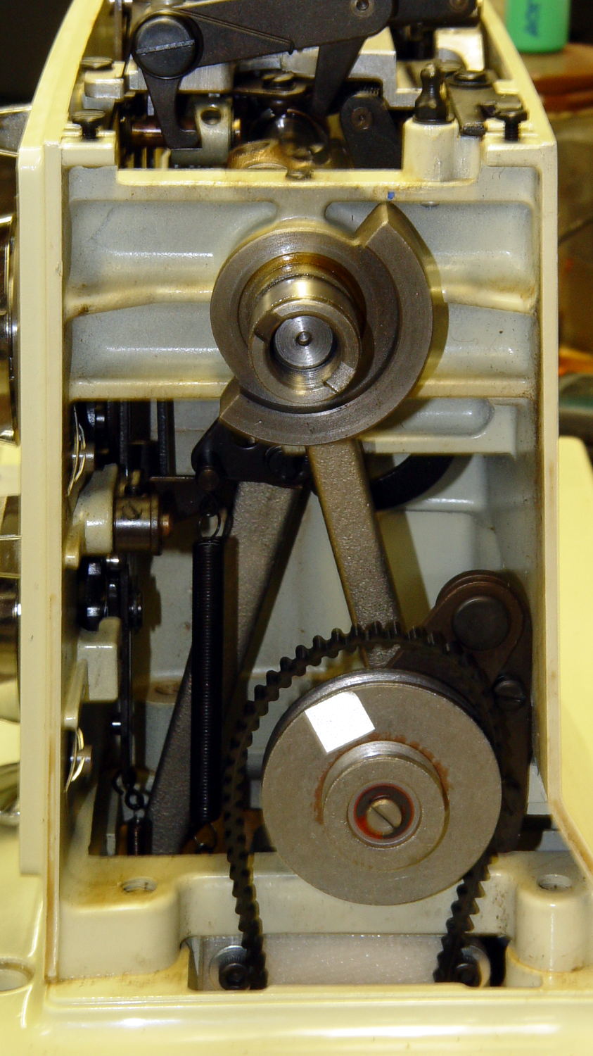
As you’d expect, with the shaft rotated exactly 180° from that point, the needle is up.
The inviting space just above the shaft provides room for the bobbin winder that engages a knurled ring on the back of the handwheel, but the lower space seems to be available. The counterweight sits about halfway into the back of the handwheel, so the sensors must look at the frame side of the counterweight.
Two adjacent sensors could detect the edge of the counterweight, which would be enough to uniquely identify both positions. If they were spaced across the lower-left edge in that picture:
- 01 = trailing edge = bottom dead center = needle down (as shown)
- 00 = open air = needle rising
- 10 = leading edge = top dead center = needle up
- 11 = solid steel = needle falling
Either sensor gives you one pulse per handwheel revolution and the combination gives you a quadrature output of both position and direction. The top speed of 1000 RPM produces 17 Hz square waves.
An additional pulse/rev sensor on the motor shaft would give better control over the motor speed, as the handwheel runs at 1/10 the motor speed with belt slip built right in. Figure 10 kRPM → 170 Hz pulses.
From a cold start, you know the shaft angle to within a bit under 180°. If the motor can turn in both directions (as would a stepper or DC motor), you can always move the needle upward. If it turns only forward (as does the AC motor) and the needle is falling, then you probably don’t want to move the motor until you get a button push indicating that all fingers are clear.
A pair of Hall effect sensors might suffice to detect that big hunk of steel, perhaps with a pair of teeny magnets glued to the face or a magnetic circuit closed by the counterweight.
More pondering is in order.

Comments
4 responses to “Kenmore 158: Needle Position Sensing”
How about an optical approach? You could mount a patterned disk to the counterweight’s shaft — that keyway and hollow shaft looks promising — and sense with an optical interrupter. That would allow an arbitrary degree of resolution of position, pretty much.
The handwheel covers everything on the outer end of the shaft and about 3/4 of the counterweight, alas. As nearly as I can tell, they installed the shaft and built the rest of the machinery around it; there’s no way to get access to either end.
Maybe, just maybe, I could engrave / mark / glue a pattern on the inside of the handwheel, then sense it somewhere between the counterweight and the belt. I think there’s room above the jackshaft pulley, which flops around too much to have a pattern on its backside…
Thanks for the idea!
The handwheel also has the advantage of being a replacable part, which is always nice. I’d be tempted to drill n magnets into the handwheel’s periphery and use a hall effect sensor to pick them up rather than optical (i’ve never had much luck with reflective optical sensing).
Time to pick up a bunch of digital Hall effect sensors and some teeny neodymium magnets…
Something I forgot: you disconnect the handwheel from the shaft when winding thread on the bobbin, so there’s no permanent connection between the motor-go-round and the shaft-go-round. The needle feedback loop must detect an unlocked handwheel and gracefully stand down, rather than going nuts spinning the motor.
I like the combination of counterweight and handwheel position sensing, although the mode switching shouldn’t require a manual selection other than just unlocking the handwheel.