Sean reports that the first field test of the Tux Cookie Cutter went well:
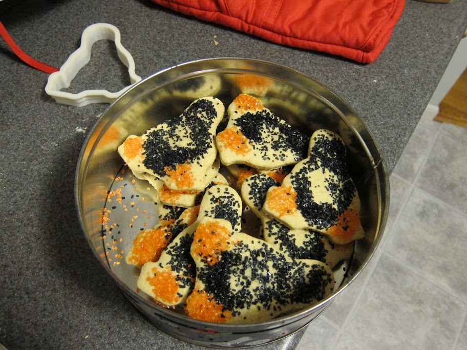
I obviously need a few samples for QC purposes…
The Smell of Molten Projects in the Morning
Ed Nisley's Blog: Shop notes, electronics, firmware, machinery, 3D printing, laser cuttery, and curiosities. Contents: 100% human thinking, 0% AI slop.
Using and tweaking a Makerbot Thing-O-Matic 3D printer
Sean reports that the first field test of the Tux Cookie Cutter went well:
I obviously need a few samples for QC purposes…
Picked up a Harbor Freight thickness gauge to measure Thing-O-Matic filaments and suchlike; it has a plastic piston and anvil, so it’s not well-suited to measure anything other than plastic parts. In fact, it’s all plastic and the various sliding surfaces produced a remarkable amount of friction.
Fortunately, the back cover pops off without too much of a struggle:
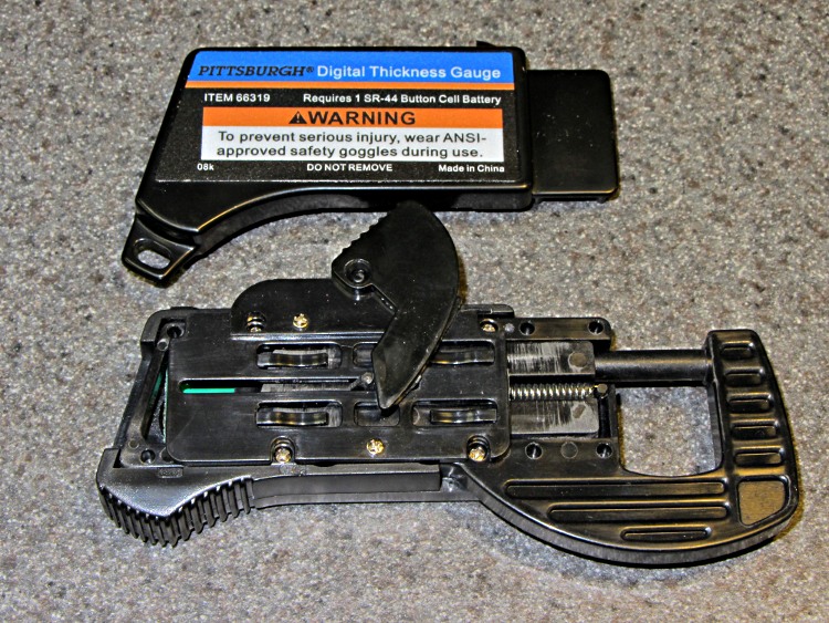
Dabs of silicone lube at all the contact points considerably improved its disposition.
The display offers 0.01 mm resolution, but I don’t believe that rightmost digit for an instant. The stated accuracy is ±0.1 mm, which is probably closer to the truth, and it agrees reasonably well with my considerably better quality digital caliper.
It always feels good when the parts fit together, even if they don’t actually do anything yet…
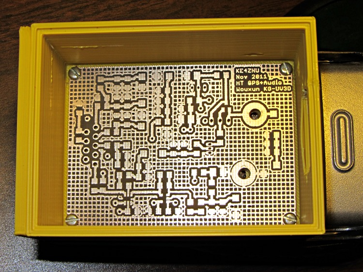
That’s the bare PCB in the first-pass 3D-printed battery case adapter, both of which need quite a bit more work. In particular, the case desperately needs some sort of latch to hold the yet-to-be-built contacts against the HT’s battery terminals.
Amazingly, all the holes lined up spot on, although I think the lower battery contact could move half a millimeter closer to the base of the radio. The battery case contacts are large enough to work as-is and, for what it’s worth, the Wouxun battery cases seem to differ slightly among themselves, too.
The PCB itself came out about as well as any homebrew PCB I’ve ever made, after getting the Logitech Joggy Thing working again to line the Sherline up for hole drilling:
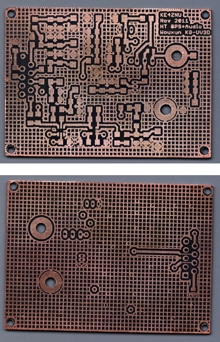
The circuit has provision for pairs of SMD caps on all the inputs, with which I hope to squash RFI from both the VHF and UHF amateur bands by choosing their self-resonant frequencies appropriately.
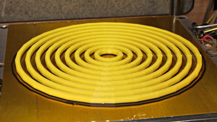
Flushed with success on the small-hole front, I conjured up a large hole testpiece using the same HoleAdjust function that proved unnecessary with the little ones:

The first version didn’t have the cross bars, which turned out to be a mistake, because the individual rings distorted even under minimal pressure from the calipers:
However, measuring as delicately as I could, the holes seemed a scant 0.20 mm too small, more or less, kinda-sorta:
| Nominal | Nom+0.0 |
| 10 | 9.83 |
| 20 | 19.75 |
| 30 | 29.85 |
| 40 | 39.84 |
| 50 | 49.84 |
| 60 | 59.72 |
| 70 | 64.76 |
| 80 | 79.28 |
| 90 | 89.77 |
So I fed in HoleFinagle = 0.20 and the second iteration looks like it’d make a great, albeit leaky, coaster:
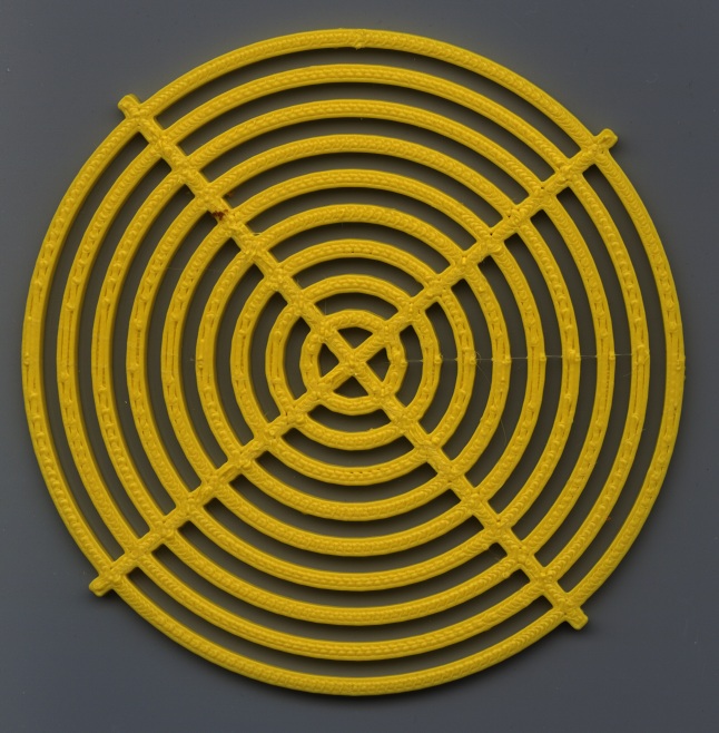
Measuring those holes across the center with the calipers on facets (rather than vertices), produced somewhat more stable results:
| Nominal | Nom+0.20 |
| 10 | 10.08 |
| 20 | 20.17 |
| 30 | 30.08 |
| 40 | 40.08 |
| 50 | 50.00 |
| 60 | 60.02 |
| 70 | 70.05 |
| 80 | 79.98 |
| 90 | 90.07 |
Frankly, I don’t believe those two least-significant digits, either, because a different set of measurements across different facets looked like this:
| Nominal | Nom+0.20 |
| 10 | 10.13 |
| 20 | 20.11 |
| 30 | 29.84 |
| 40 | 39.90 |
| 50 | 49.88 |
| 60 | 59.90 |
| 70 | 69.84 |
| 80 | 79.82 |
| 90 | 89.66 |
I also printed a testpiece with HoleFinagle = 0.25 that averaged, by in-the-head computation, about 0.05 larger than that, so the hole diameter compensation does exactly what it should.
Applying the calipers to the 10.0 mm hole in the small-hole testpiece gives about the same result as in this one. The fact that HoleFinagle is different poses a bit of a mystery…
The only thing I can conclude is that the measurement variation and the printing variation match up pretty closely: the actual diameter depends more on where it’s measured than anything else. The holes are pretty nearly the intended size and, should the exact size matter, you (well, I) must print at least one to throw away.
All in all, a tenth of a millimeter is Good Enough. Selah.
Oh. The ODs are marginally too small, even using PolyCyl.
The OpenSCAD source, with both adjustments set to neutral:
// Large circle diameter calibration
// Ed Nisley KE4ZNU - Nov 2011

//-------
//- Extrusion parameters must match reality!
//  Print with +1 shells, 3 solid layers, 0.2 infill

ThreadThick = 0.33;
ThreadWidth = 2.0 * ThreadThick;

HoleFinagle = 0.00;
HoleFudge = 1.00;

function HoleAdjust(Diameter) = HoleFudge*Diameter + HoleFinagle;

Protrusion = 0.1;			// make holes end cleanly

function IntegerMultiple(Size,Unit) = Unit * ceil(Size / Unit);

//-------
// Dimensions

Width = 2.5;
Thickness = IntegerMultiple(2.0,ThreadThick);

DiaStep = 10.0;

NumCircles = 9;

echo(str("Width: ",Width));
echo(str("Thickness: ",Thickness));

BarLength = (NumCircles + 1)*DiaStep;

//-------

module PolyCyl(Dia,Height,ForceSides=0) {			// based on nophead's polyholes

  Sides = (ForceSides != 0) ? ForceSides : (ceil(Dia) + 2);

  FixDia = Dia / cos(180/Sides);

  cylinder(r=HoleAdjust(FixDia)/2,h=Height,$fn=Sides);
}

module ShowPegGrid(Space = 10.0,Size = 1.0) {

  Range = floor(50 / Space);

	for (x=[-Range:Range])
	  for (y=[-Range:Range])
		translate([x*Space,y*Space,Size/2])
		  %cube(Size,center=true);

}

//------

module Ring(RingID,Width,Thick) {

  difference() {
	PolyCyl((RingID + 2*Width),Thick);
	translate([0,0,-Protrusion])
	  PolyCyl(RingID,(Thick + 2*Protrusion));
  }
}

//------

ShowPegGrid();

union () {
  for (Index = [1:NumCircles])
	Ring(Index*DiaStep,Width,Thickness);
  for (Index = [-1,1])
	rotate(Index*45)
	  translate([-BarLength/2,-Width/2,0])
		cube([BarLength,Width,Thickness]);
}
The macro lens & microscope adapters for the Canon SX230HX camera required a bunch of large and fairly precise circles. The first-pass prints of the main tube and snouts came out with diameters about 2% too small, so I changed the hole diameter compensation to include a first-order Fudge Factor as well as the simple zero-order HoleWindage Finagle Constant I’d been using. In the process, I cooked up a simple OpenSCAD function with new coefficient names reflecting their order:
HoleFinagle = 0.20;
HoleFudge = 1.02;
function HoleAdjust(Diameter) = HoleFudge*Diameter + HoleFinagle;
That solved the immediate issue, but I wondered whether I was working on the right problem.
In the past, nophead’s polyholes testpiece showed the need for the 0.2 mm HoleWindage adder to make small holes turn out correctly. I rewrote his code to:
Which came out like this:
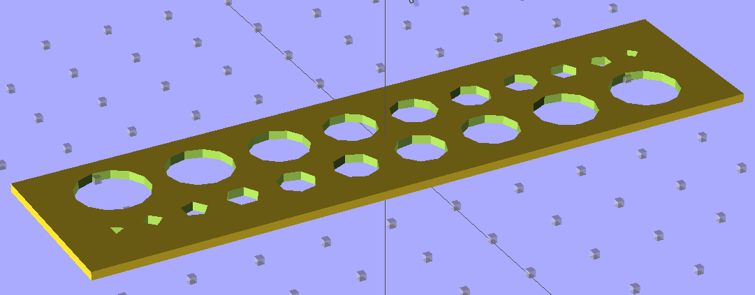
To find out where I’m starting from, I printed it (0.33 mm x 0.66 mm, 30 mm/s, 200 °C / 110 °C) with both correction factors set to “no change” and got a nice-looking plate that didn’t require any cleanup at all:

Note that the similar-looking holes in the two rows aren’t the same size: the row with the tiny triangle has *.0 mm holes, the tiny square marks the *.5 mm holes.
The Skirt thread thickness was 0.31 to 0.38 mm, so this object’s size should be about as good as it gets.
The point of the game is to circumscribe polygonal holes around a cylinder of a given diameter. I don’t have a set of metric drills (or drill rods), so I bracketed the holes with the nearest sizes of hard-inch number and letter drills:
| Nominal | Free fit | Snug fit | |
| 1.00 | 0.98 | 1.04 | |
| 2.00 | 2.05 | 2.18 | |
| 3.00 | 2.93 | 3.03 | |
| 4.00 | 3.99 | 4.04 | |
| 5.00 | 5.06 | 5.13 | |
| 6.00 | 6.21 | 6.23 | no-go |
| 7.00 | 6.98 | 7.12 | |
| 8.00 | 7.50 | 8.19 | |
| 9.00 | 8.77 | 9.05 | |
| 10.00 | 9.92 | 10.19 | tight |
The “snug fit” column means the holes are definitely smaller than that measurement, so the maximum hole size comes out just about spot on; an error of 0.1 mm or so seems too small to quibble over.
So, for whatever reason, my previous Finagle Constant of 0.20 seems no longer necessary and, for sure, the Fudge Factor doesn’t bring anything to the table at this scale.
It’s definitely true that the height of the first layer affects the hole size for the next few layers, even with the Z-minimum switch measuring the build plate height. The Skirt threads generally measure within ±0.05 mm of the nominal 0.33 mm and I think much of that variation comes from residual snot on the nozzle when it touches the switch. I have no idea what the firmware’s resolution might be.
Given that I’ve been adding 0.2 mm to small-hole diameters all along, I suspect all these errors are now of the same general size:
All in all, it’s pretty good.
The OpenSCAD source code, with the hole adjustment factors set to neutral:
// Small circle diameter calibration
// Adapted from Nophead's polyholes testpiece
// Ed Nisley - KE4ZNU - Nov 2011

//-------
//- Extrusion parameters must match reality!
//  Print with +1 shells, 3 solid layers, 0.2 infill

ThreadThick = 0.33;
ThreadWidth = 2.0 * ThreadThick;

HoleFinagle = 0.00;
HoleFudge = 1.00;

function HoleAdjust(Diameter) = HoleFudge*Diameter + HoleFinagle;

Protrusion = 0.1;			// make holes end cleanly

function IntegerMultiple(Size,Unit) = Unit * ceil(Size / Unit);

//-------
// Dimensions

DiaStep = 1.0;

NumHoles = 10;

Border = 5*ThreadWidth;

AllHoleLength = DiaStep*(NumHoles*(NumHoles + 1)/2) +	// total hole dia
				(NumHoles + 1)*Border +					// total border size
				DiaStep*NumHoles/2;						// radius of largest hole

BlockLength = AllHoleLength + 2*Border;
BlockWidth = 2*NumHoles*DiaStep + 2*Border;
BlockThick = IntegerMultiple(1.0,ThreadThick);

//-------

module PolyCyl(Dia,Height,ForceSides=0) {			// based on nophead's polyholes

  Sides = (ForceSides != 0) ? ForceSides : (ceil(Dia) + 2);

  FixDia = Dia / cos(180/Sides);

  cylinder(r=HoleAdjust(FixDia)/2,h=Height,$fn=Sides);
}

module ShowPegGrid(Space = 10.0,Size = 1.0) {

  Range = floor(50 / Space);

	for (x=[-Range:Range])
	  for (y=[-Range:Range])
		translate([x*Space,y*Space,Size/2])
		  %cube(Size,center=true);

}

//------

module HoleRow(DiaDelta) {

  translate([-AllHoleLength/2,
			  0,0])
	for (Index = [1:NumHoles])
	  translate([(DiaStep*(Index*(Index + 1)/2) + Index*Border),0,-Protrusion])
		PolyCyl((Index*DiaStep + DiaDelta),(BlockThick + 2*Protrusion));
}

//------

ShowPegGrid();

rotate(90)
  difference() {
	translate([-BlockLength/2,-BlockWidth/2,0])
	  cube([BlockLength,BlockWidth,BlockThick]);
	for (Index = [0,1])
	  translate([0,((2*Index - 1)*DiaStep*NumHoles/2),0])
		rotate(Index*180)
		  HoleRow(Index*0.5);
  }
The main tube connects the camera mounting plate and the snout on the front, so it’s a structural element of a sort. The ID fits over the non-moving lens turret base on the camera and the inner length is a few millimeters longer than the maximum lens turret extension:

As you might expect by now, the front bulkhead has four alignment peg holes for the snout:
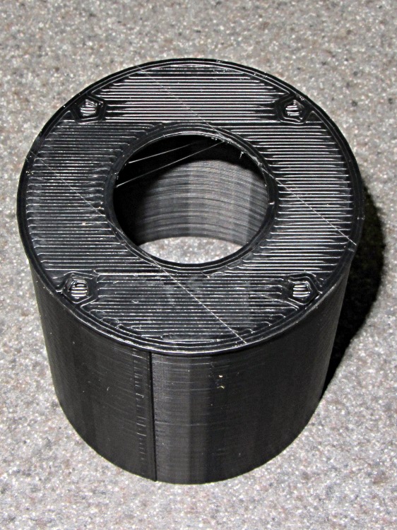
The OpenSCAD code sets the wall thickness to 3 thread widths, but Skeinforge prints two adjacent threads with no fill at all. I think the polygon corners eliminate the one-thread-width fill and the perimeter threads wind up near enough to merge properly.
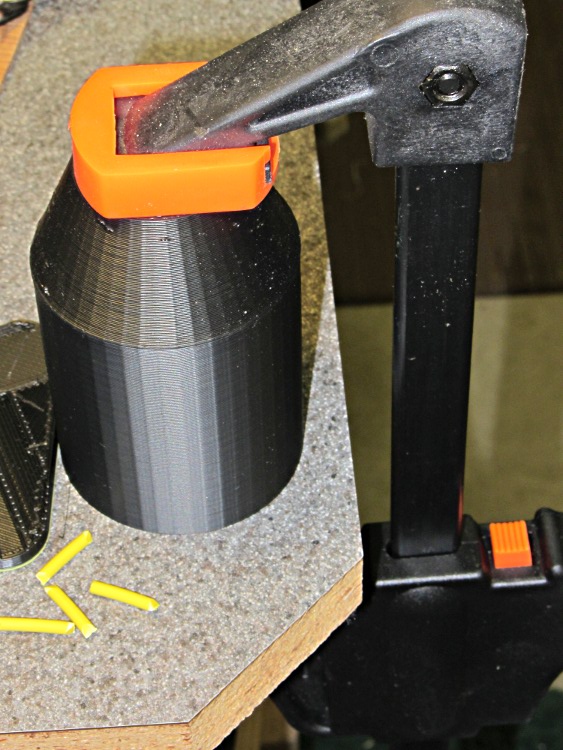
I assembled snouts to main tubes first, because it was easier to clamp bare cylinders to the bench:
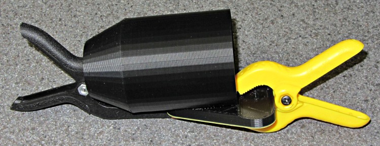
Then glue the tube to the mounting plate using a couple of clamps:
The alignment is pretty close to being right, but if when I do this again I’ll add alignment pegs along the trench in the mounting plate to make sure the tube doesn’t ease slightly to one side, thusly:
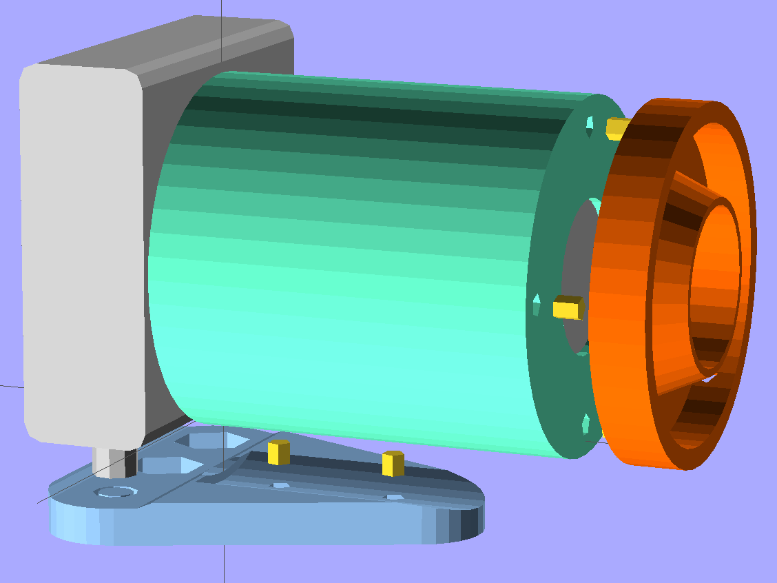
You can see the entrance pupil isn’t quite filled in the last picture there, so a bit more attention to detail is in order. A bigger doublet lens would help, too.
The current version of the OpenSCAD source code with those pegs:
// Close-up lens mount & Microscope adapter for Canon SX230HS camera
// Ed Nisley KE4ZNU - Nov 2011

Mount = "LEDRing";			// End result: LEDRing Eyepiece

Layout = "Show";			// Assembly: Show
							// Parts: Plate Tube LEDRing Camera Eyepiece
							// Build Plates: Build1..4

Gap = 10;					// between "Show" objects

include </home/ed/Thing-O-Matic/lib/MCAD/units.scad>
include </home/ed/Thing-O-Matic/Useful Sizes.scad>
include </home/ed/Thing-O-Matic/lib/visibone_colors.scad>

//-------
//- Extrusion parameters must match reality!
//  Print with +1 shells, 3 solid layers, 0.2 infill

ThreadThick = 0.33;
ThreadWidth = 2.0 * ThreadThick;

HoleFinagle = 0.2;
HoleFudge = 1.00;

function HoleAdjust(Diameter) = HoleFudge*Diameter + HoleFinagle;

Protrusion = 0.1;			// make holes end cleanly

function IntegerMultiple(Size,Unit) = Unit * ceil(Size / Unit);

//-------
// Dimensions

// doublet lens

LensDia = 25.0;
LensRad = LensDia/2;
LensClearance = 0.2;

LensEdge = 6.7;
LensThick = 8.6;
LensRimThick = IntegerMultiple((2.0 + LensThick),ThreadThick);

// LED ring light

LEDRingOD = 50.0;
LEDRingID = 36.0;
LEDBoardThick = 1.5;
LEDThick = 4.0;
LEDRingClearance = 0.5;
LEDWireHoleDia = 3.0;

// microscope eyepiece

EyepieceOD = 30.0;
EyepieceID = 24.0;
EyepieceLength = 25.0;

// camera
// Origin at base of [0] ring, Z+ along lens axis, X+ toward bottom, Y+ toward left

CameraBodyWidth = 2*10.6;							// 2 x center-to-curve edge
CameraBaseWidth = 15.5;								// flat part of bottom front to back
CameraBaseRadius = (CameraBodyWidth - CameraBaseWidth)/2;	// edge rounding
CameraBaseLength = 60.0;							// centered on lens axis
CameraBaseHeight = 55.0;							// main body height
CameraBaseThick = 0.9;								// downward from lens ring

echo(str("Camera base radius: ",CameraBaseRadius));

TripodHoleOffset = -19.0;							// mount screw wrt lens centerline
TripodHoleDia = Clear025_20;						// clearance hole

TripodScrewHeadDia = 14.5;							// recess for screw mounting camera
TripodScrewHeadRad = TripodScrewHeadDia/2;
TripodScrewHeadThick = 3.0;

// main lens tube

TubeDia = 		[53.0,	44.0,	40.0,	37.6];		// lens rings, [0] is fixed to body
TubeLength = 	[8.1,	20.6,	17.6,	12.7];

TubeEndClearance = 2.0;								// camera lens end to tube end
TubeEndThickness = IntegerMultiple(1.5,ThreadThick);
TubeInnerClearance = 0.5;

TubeInnerLength = TubeLength[0] + TubeLength[1] + TubeLength[2] + TubeLength[3] +
				  TubeEndClearance;
TubeOuterLength = TubeInnerLength + TubeEndThickness;

TubeID = TubeDia[0] + TubeInnerClearance;
TubeOD = TubeID + 6*ThreadWidth;
TubeWall = (TubeOD - TubeID)/2;
TubeSides = 48;

echo(str("Main tube outer length: ",TubeOuterLength));
echo(str("          ID: ",TubeID," OD: ",TubeOD," wall: ",TubeWall));

// camera mounting base

BaseWidth = IntegerMultiple((CameraBaseWidth + 2*CameraBaseRadius),ThreadThick);
BaseLength = 60.0;
BaseThick = IntegerMultiple((1.0 + Nut025_20Thick + CameraBaseThick),ThreadThick);

// LED ring mount

LEDBaseThick = IntegerMultiple(2.0,ThreadThick);	// base under lens + LED ring
LEDBaseRimWidth = IntegerMultiple(6.0,ThreadWidth);
LEDBaseRimThick = IntegerMultiple(LensThick,ThreadThick);

LEDBaseOD = max((LEDRingOD + LEDRingClearance + LEDBaseRimWidth),TubeOD);

echo(str("LED Ring OD: ",LEDBaseOD));

// alignment pins between tube and LED ring / microscope eyepiece

AlignPinOD = 2.9;

SnoutPins = 4;
SnoutPinCircleDia = TubeOD - 2*TubeWall - 2*AlignPinOD;		// 2*PinOD -> more clearance

// alignment pins between tube and base plate

BasePins = 2;
BasePinOffset = 10.0;
BasePinSpacing = BaseLength/3;

//-------

module PolyCyl(Dia,Height,ForceSides=0) {			// based on nophead's polyholes

  Sides = (ForceSides != 0) ? ForceSides : (ceil(Dia) + 2);

  FixDia = Dia / cos(180/Sides);

  cylinder(r=HoleAdjust(FixDia)/2,h=Height,$fn=Sides);
}

module ShowPegGrid(Space = 10.0,Size = 1.0) {

  Range = floor(50 / Space);

	for (x=[-Range:Range])
	  for (y=[-Range:Range])
		translate([x*Space,y*Space,Size/2])
		  %cube(Size,center=true);

}

//-------

//- Camera body segment
//	Including lens base and peg for tripod hole access
//	Z=0 at edge of lens base ring, X=0 along lens axis

module CameraBody() {

  translate([0,0,-CameraBaseThick])
	rotate(90)
	  union() {
		translate([0,0,(CameraBaseHeight/2 + CameraBaseRadius)])
		  minkowski() {
			cube([CameraBaseWidth,
				  (CameraBaseLength + 2*Protrusion),
				  CameraBaseHeight],center=true);
			rotate([90,0,0])
			  cylinder(r=CameraBaseRadius,h=Protrusion,$fn=8);
		  }

		translate([0,0,(TubeDia[0]/2 + CameraBaseThick)])
		  rotate([0,90,0])
			rotate(180/TubeSides)
			  cylinder(r=(TubeDia[0]/2 + CameraBaseThick),
					  h=(CameraBodyWidth/2 + Protrusion),
					  $fn=TubeSides);

		translate([CameraBodyWidth/2,0,(TubeDia[0]/2 + CameraBaseThick)])
		  rotate([0,90,0])
			cylinder(r=TubeDia[0]/2,h=TubeLength[0]);

		translate([(TubeLength[0] + CameraBodyWidth/2),
				  0,(TubeDia[0]/2 + CameraBaseThick)])
		  rotate([0,90,0])
			cylinder(r=TubeDia[1]/2,h=TubeLength[1]);

		translate([(TubeLength[0] + TubeLength[1] + CameraBodyWidth/2),
				  0,(TubeDia[0]/2 + CameraBaseThick)])
		  rotate([0,90,0])
			cylinder(r=TubeDia[2]/2,h=TubeLength[2]);

		translate([(TubeLength[0] + TubeLength[1] + TubeLength[2] + CameraBodyWidth/2),
				  0,(TubeDia[0]/2 + CameraBaseThick)])
		  rotate([0,90,0])
			cylinder(r=TubeDia[3]/2,h=TubeLength[3]);

		translate([0,TripodHoleOffset,-BaseThick])
		  PolyCyl(TripodHoleDia,(BaseThick + 2*Protrusion));

	  }
}

//- Main tube

module Tube() {

  difference() {
	cylinder(r=TubeOD/2,h=TubeOuterLength,$fn=TubeSides);

	translate([0,0,TubeEndThickness])
	  PolyCyl(TubeID,(TubeInnerLength + Protrusion),TubeSides);

	translate([0,0,-Protrusion]) {
	  if (Mount == "LEDRing")
		cylinder(r=LensRad,h=(TubeEndThickness + 2*Protrusion));
	  if (Mount == "Eyepiece")
		cylinder(r=EyepieceID/2,h=(TubeEndThickness + 2*Protrusion));
	}

	for (Index = [0:SnoutPins-1])
	  rotate(Index*90)
		translate([(SnoutPinCircleDia/2),0,-ThreadThick])
		  rotate(180)			// flat sides outward
			PolyCyl(AlignPinOD,TubeEndThickness);

	for (Index = [0:BasePins-1])
		translate([0,-(TubeOD/2 + Protrusion),
				  (TubeOuterLength - BasePinOffset - Index*BasePinSpacing)])
		  rotate([-90,90,0])					// y = flat toward camera
			PolyCyl(AlignPinOD,(TubeWall + 2*Protrusion));
  }

}

//- Base plate

module BasePlate() {

  union() {
	difference() {
		linear_extrude(height=BaseThick)
		  hull() {
			translate([-(BaseLength/2 - BaseWidth/2),0,0])
			  circle(BaseWidth/2);
			translate([ (BaseLength/2 - BaseWidth/2),0,0])
			  circle(BaseWidth/2);
			translate([0,(0.75*BaseLength),0])
			  circle(BaseWidth/2);
		  }

		translate([0,0,BaseThick])
		  CameraBody();

		translate([0,(TubeOuterLength + CameraBodyWidth/2),
				  (BaseThick + TubeDia[0]/2)])
		  rotate([90,0,0])
			PolyCyl(TubeOD,TubeOuterLength,$fn=TubeSides);

		for (Index = [0:BasePins-1])
			translate([0,(CameraBodyWidth/2 + BasePinOffset + Index*BasePinSpacing),
					  3*ThreadThick])
			  rotate(90)										// flat toward camera
				PolyCyl(AlignPinOD,BaseThick);

		translate([0,0,3*ThreadThick])
		  PolyCyl((Nut025_20Dia*sqrt(3)/2),2*Nut025_20Thick,6);	// dia across hex flats

		translate([0,0,-Protrusion])
		  PolyCyl(Clear025_20,(BaseThick + 2*Protrusion));

		translate([TripodHoleOffset,0,3*ThreadThick])
		  PolyCyl((Nut025_20Dia*sqrt(3)/2),2*Nut025_20Thick,6);	// dia across hex flats

		translate([TripodHoleOffset,0,-Protrusion])
		  PolyCyl(Clear025_20,(BaseThick + 2*Protrusion));

		translate([-TripodHoleOffset,0,-Protrusion])
		  PolyCyl(TripodScrewHeadDia,(TripodScrewHeadThick + Protrusion));
	}

	translate([-TripodHoleOffset,0,0]) {				// support for tripod screw hole
	  for (Index=[0:3])
		rotate(Index*45)
		  translate([-ThreadWidth,-TripodScrewHeadRad,0])
			cube([2*ThreadWidth,TripodScrewHeadDia,TripodScrewHeadThick]);

	  cylinder(r=0.4*TripodScrewHeadRad,h=(BaseThick - CameraBaseThick),$fn=9);
	}
  }
}

//- LED mounting ring

module LEDRing() {

  difference() {
	cylinder(r=LEDBaseOD/2,h=LensRimThick,$fn=48);

	translate([0,0,-Protrusion])
	  PolyCyl((LensDia + LensClearance),
			  (LensRimThick + 2*Protrusion));

	translate([0,0,LEDBaseRimThick])
	  difference() {
		PolyCyl(LEDBaseOD,LensThick);
		PolyCyl(LEDRingID,LensThick);
	  }

	translate([0,0,LEDBaseThick])
	  difference() {
		PolyCyl((LEDRingOD + LEDRingClearance),LensThick);
		cylinder(r1=HoleAdjust(LEDRingID - LEDRingClearance)/2,
				 r2=HoleAdjust(LensDia + LensClearance)/2 + 2*ThreadWidth,
				 h=LensThick);
	  }

	for (Index = [0:SnoutPins-1])
	  rotate(Index*90)
		translate([(SnoutPinCircleDia/2),0,-ThreadThick])
		  rotate(180)			// flat sides outward
			PolyCyl(AlignPinOD,LEDBaseThick);

	rotate(45)
	  translate([0,LEDRingID/2,(LEDBaseThick + 1.2*LEDWireHoleDia/2)])
		rotate([0,-90,0])			// flat side down
		  rotate([-90,0,0])
			PolyCyl(LEDWireHoleDia,2*LEDBaseRimWidth);
  }

}

//- Microscope eyepiece adapter

module EyepieceMount() {

  difference() {
	cylinder(r1=TubeOD/2,
			 r2=(EyepieceOD + 8*ThreadWidth)/2,
			 h=EyepieceLength,
			 $fn=TubeSides);

	translate([0,0,-Protrusion])
	  PolyCyl(EyepieceOD,(EyepieceLength + 2*Protrusion));

	for (Index = [0:SnoutPins-1])
	  rotate(Index*90)
		translate([(SnoutPinCircleDia/2),0,-ThreadThick])
		  rotate(180)			// flat sides outward
			PolyCyl(AlignPinOD,6*ThreadThick);
  }

}

//-------
// Build it!

if (Layout != "Show")
  ShowPegGrid();

if (Layout == "Tube")
  Tube();

if (Layout == "LEDRing")
  LEDRing();

if (Layout == "Plate")
  BasePlate();

if (Layout == "Camera")
  CameraBody();

if (Layout == "Eyepiece")
  EyepieceMount();

if (Layout == "Build1")
  translate([0,-BaseLength/3,0])
	BasePlate();

if (Layout == "Build2")
  Tube();

if (Layout == "Build3")
  LEDRing();

if (Layout == "Build4")
  EyepieceMount();

if (Layout == "Show") {
  translate([0,TubeOuterLength,TubeDia[0]/2]) {
	rotate([90,0,0])
	  color(LTC) Tube();
	translate([0,(Gap/2 - TubeEndThickness - Protrusion),0])
	  rotate([-90,0,0])
		for (Index = [0:SnoutPins-1])
		  rotate(Index*90)
			translate([(SnoutPinCircleDia/2),0,0])
			  rotate(180)			// flat sides outward
				PolyCyl(AlignPinOD,(TubeEndThickness + LEDBaseThick));

	translate([0,Gap,0])
	  rotate([-90,0,0]) {
		if (Mount == "LEDRing")
		  color(OOR) LEDRing();
		if (Mount == "Eyepiece")
		  color(OOR) EyepieceMount();
	  }
  }

  translate([0,-CameraBodyWidth/2,0])
	color(PG) CameraBody();

  color(PDA)
	render()
	translate([0,-CameraBodyWidth/2,-(BaseThick + Gap)])
	  BasePlate();

  for (Index = [0:BasePins-1])
	  translate([0,(BasePinOffset + Index*BasePinSpacing),
				-Gap/2])
		rotate([180,0,90])										// flat toward camera
		  PolyCyl(AlignPinOD,BaseThick/2);

}
The microscope eyepiece adapter was easy enough: a cone with a cylinder punched out of it:
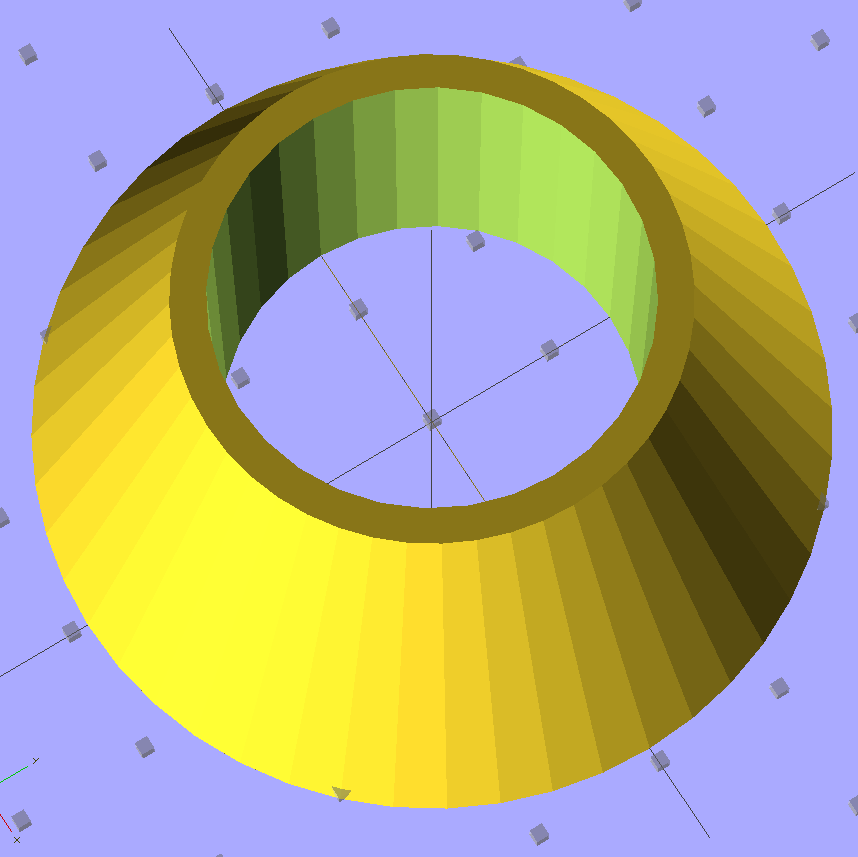
The thin part of the tip is four threads wide around the eyepiece OD, which makes for good fill.
The bottom has the usual four alignment pin holes:
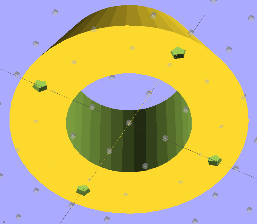
The main tube opening ID is equal to the diameter of the flat rim around the microscope eyepiece, which provides a positive stop with plenty of surface area.
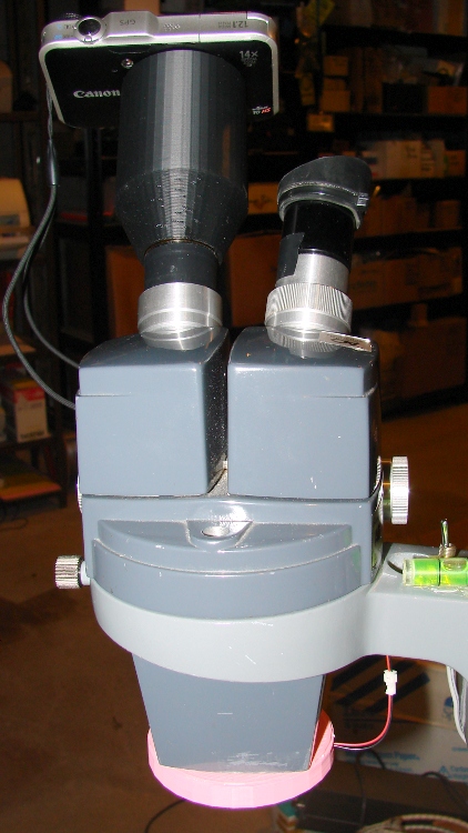
It looks about like you’d expect on the microscope, with the LED ring light from Planet Barbie around the objective lenses:
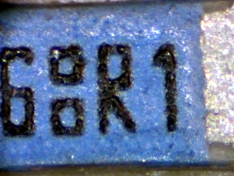
The lowest magnification is much higher than I expected; it’s about 2.5 mm across. This is a 1206 SMD resistor:
The highest magnification shows details of a laser etched numeral:
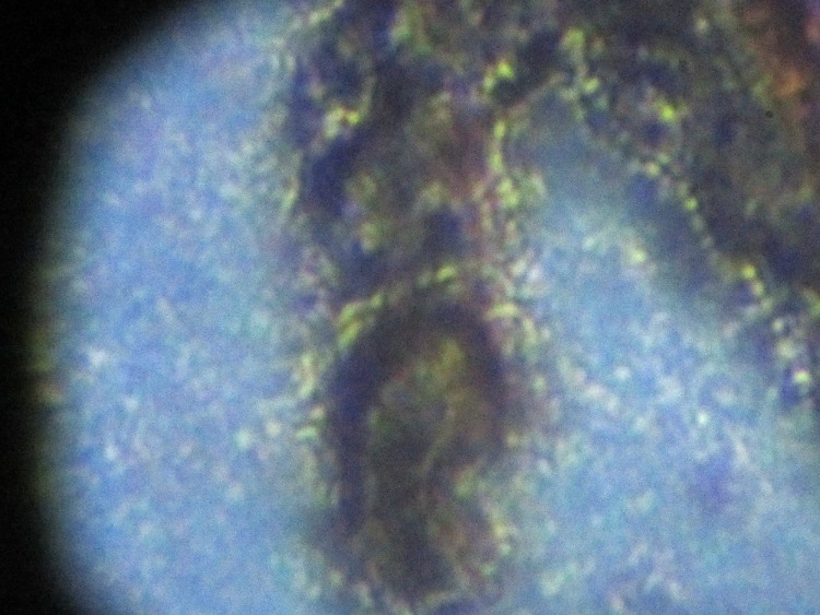
The alignment obviously isn’t up to par and I think the exposure needs some work. All in all, though, it’s usable as-is.

