Ed Nisley's Blog: Shop notes, electronics, firmware, machinery, 3D printing, laser cuttery, and curiosities. Contents: 100% human thinking, 0% AI slop.
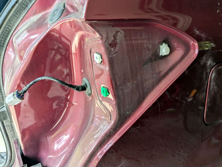
I finally got around to replacing the Forester’s taillight bulbs:
Subaru Forester taillight bulbs
The clear bulbs don’t have the same thermal damage as the headlights I replaced a year ago, but the new bulbs should be much brighter.
Subaru calls them W21/5W and WY21W, respectively, but the rest of the world says 7443 and 7440NA (or 7440A).
For the record, the taillight assembly comes off (after removing the obvious pair of screws not shown here) by pulling straight back with grippy gloves:
Subaru Forester taillight mount
Aligning the locating pins with those two latching sockets (why is one green?) requires a flashlight and a bit of dexterity, but easing the slot over the white post first helps a lot. Practice makes perfect: it’s easier on the other side of the car.
A glass-top patio table came with our house and, similar to one of the patio chairs, required some repair. The arched steel legs fit into plastic brackets / sockets around the steel table rim under the glass top:
Glass patio table – new brackets installed
The four glaringly obvious white blocks are the new brackets.
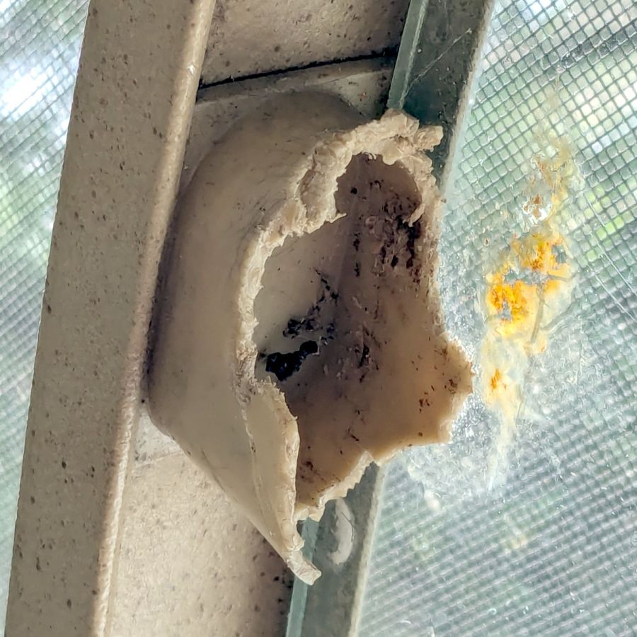
The original brackets had, over uncounted years, deteriorated:
Glass patio table – failed OEM bracket
Perhaps disintegrated would be a better description:
Glass patio table – crumbled OEM bracket
Each leg has a pair of rusted 1-½ inch ¼-20 screws holding it to the central ring. As expected, seven of the eight screws came out easily enough, with the last one requiring an overnight soak in Kroil penetrating oil plus percussive persuasion:
Glass patio table – jammed screw
The four legs had three different screws holding them to the brackets, so I drilled out the holes and squished M5 rivnuts in place:
Glass patio table – M5 rivnut installed
Although it’s not obvious, the end of that tube is beveled with respect to the centerline to put both the top and bottom edges on the table rim inside the bracket. In addition, the tube angles about 10° downward from horizontal, which I did not realize amid the wrecked fittings, so the first bracket model failed instantly as I inserted the leg:
Glass patio table – first bracket test
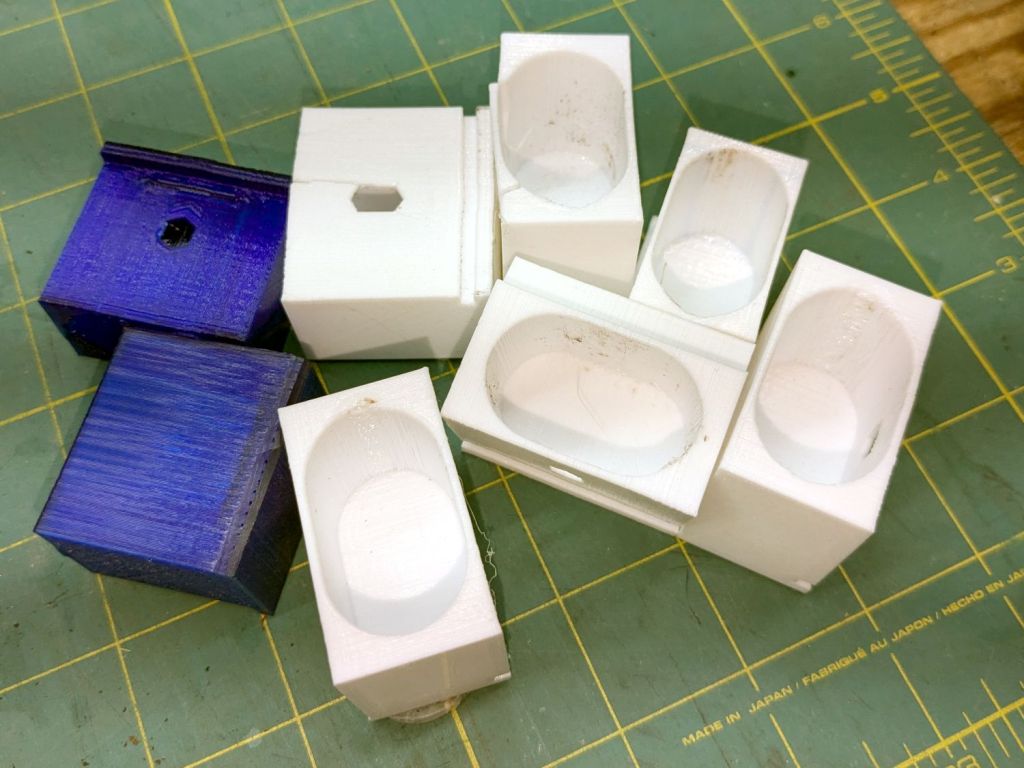
The top & bottom walls of that poor thing were breathtakingly thin (to match the original bracket) and cracked when confronted with the angled tube. I could not measure all the sizes & angles without assembling the table on trial brackets, so getting it right required considerable rapid prototyping:
Glass patio table – failed brackets
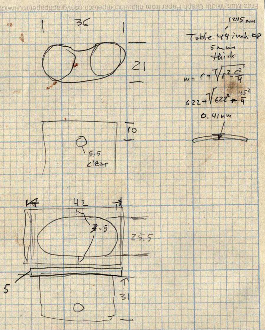
Some trigonometry produced a solid model with features rebuilding themselves around the various sizes / angles / offsets:
Glass Top Table – leg bracket – solid model
A sectioned view shows the angled tube position and end chamfer:
Glass Top Table – leg bracket – section view
The OpenSCAD code can produce a sectioned midline slice useful for laser-cut MDF pieces to check the angle:
That eliminated several bad ideas & misconceptions, although trying to balance the leg on a 3 mm MDF snippet was trickier than I expected. In retrospect, gluing a few snippets together would be easier and still faster than trying to print a similar section from the model.
The slightly elongated slot for the M5 screw shows that the original screw holes were not precisely placed or that the tubes were not precisely cut, neither of which come as a surprise. I finally built some slop into the design to eliminate the need for four different blocks keyed to four different legs.
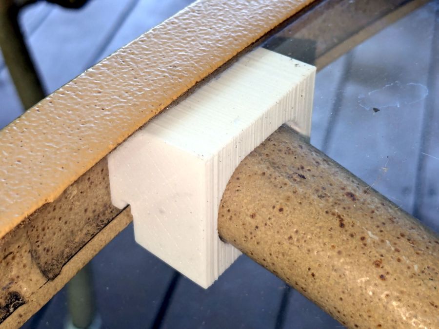
The outer rim, the notch on the bottom, and the tab on the top curve to match the four foot OD glass tabletop, with the inward side & ends remaining flat:
Glass patio table – chunky bracket installed – top
The sector’s difference from a straight line amounts to half a millimeter and improved the fit enough to justify the geometric exercise. The bracket snaps into position with the notch over the table rim and the tab locked in the gap between the glass disk & the rim, although I suspect the weight of the tabletop would keep everything aligned anyway.
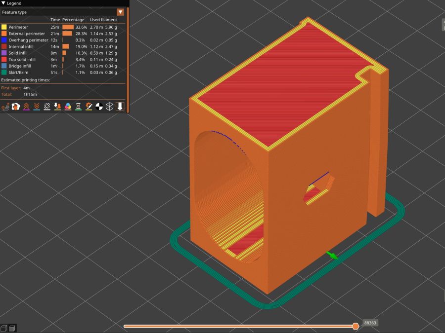
The walls are now at least 4 mm thick and, printed in PETG, came out strong enough to survive assembly and some gentle testing. They’re arranged to print on their side to eliminate support under those slight curves and to align the layers for best strength vertically in the finished bracket:
Glass Top Table – leg bracket – slicer preview
The leg cavity and screw hole built well enough without internal support.
They’re relentlessly rectangular and I’m not going to apologize one little bit.
Now to see how they survive out there on the screened porch.
This file contains hidden or bidirectional Unicode text that may be interpreted or compiled differently than what appears below. To review, open the file in an editor that reveals hidden Unicode characters.
Learn more about bidirectional Unicode characters
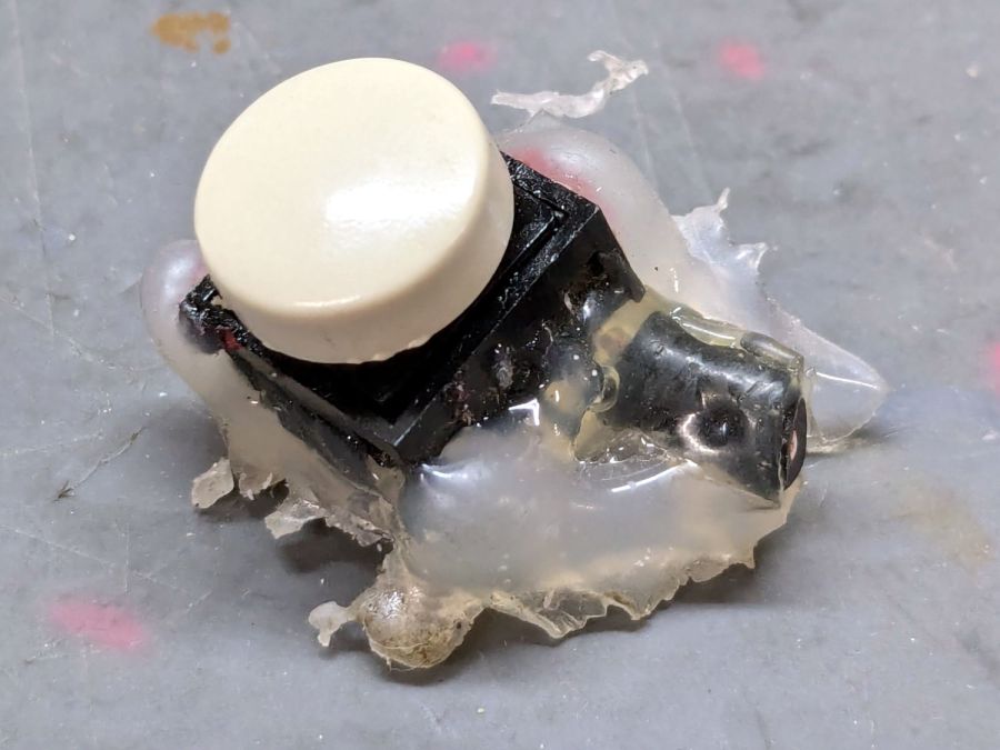
After five years and one cleaning, the PTT button on Mary’s Tour Easy became increasingly intermittent, both failing to activate solidly and sticking closed (there being nothing quite like a hot mic during a good hill climb), so it’s time for an autopsy:
Failed PTT Switch – as extracted
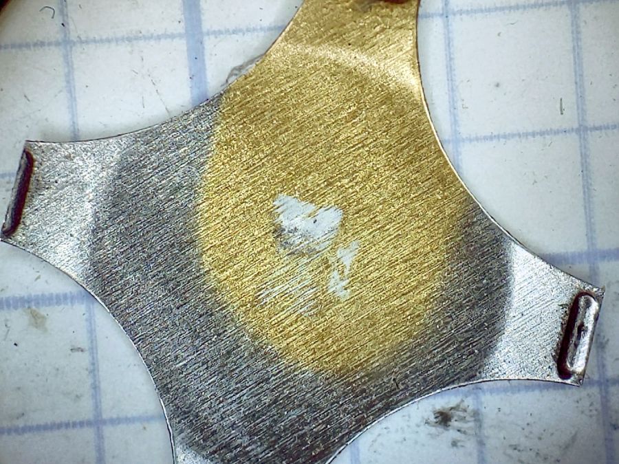
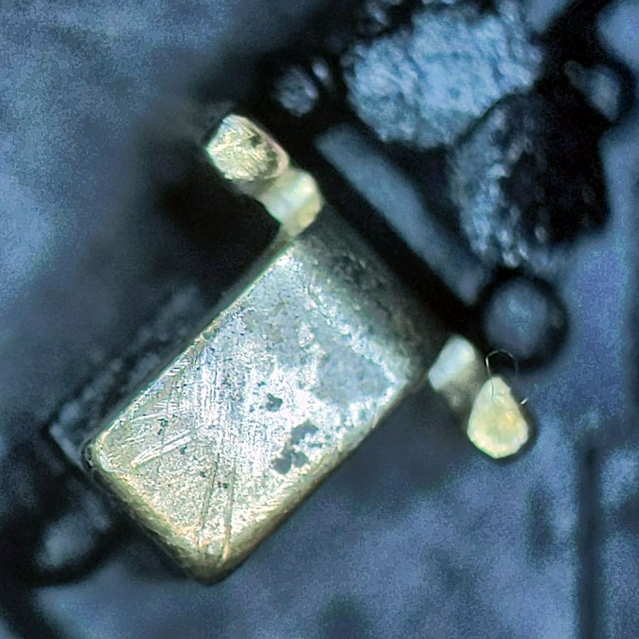
The snap dome is much more scarred at the central contact:
Failed PTT Switch – snap plate
That might be a gold flash coating, but it’s pretty well worn away where it hits the central contact:
Failed PTT Switch – center contact
Those scratches surely happened during the previous cleaning pass, as I don’t see any way for the dome to create them.
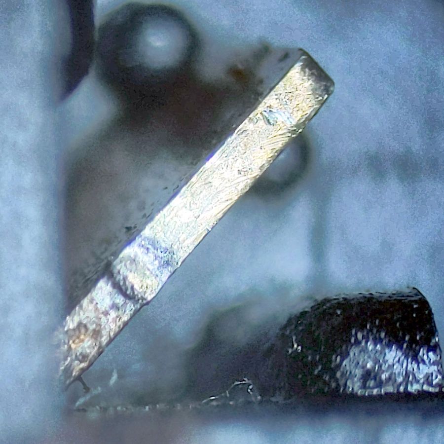
The corner contact also shows some scuffs, along with a scar where the dome corner pivots:
Failed PTT Switch – edge contact
All in all, though, it worked quite well.
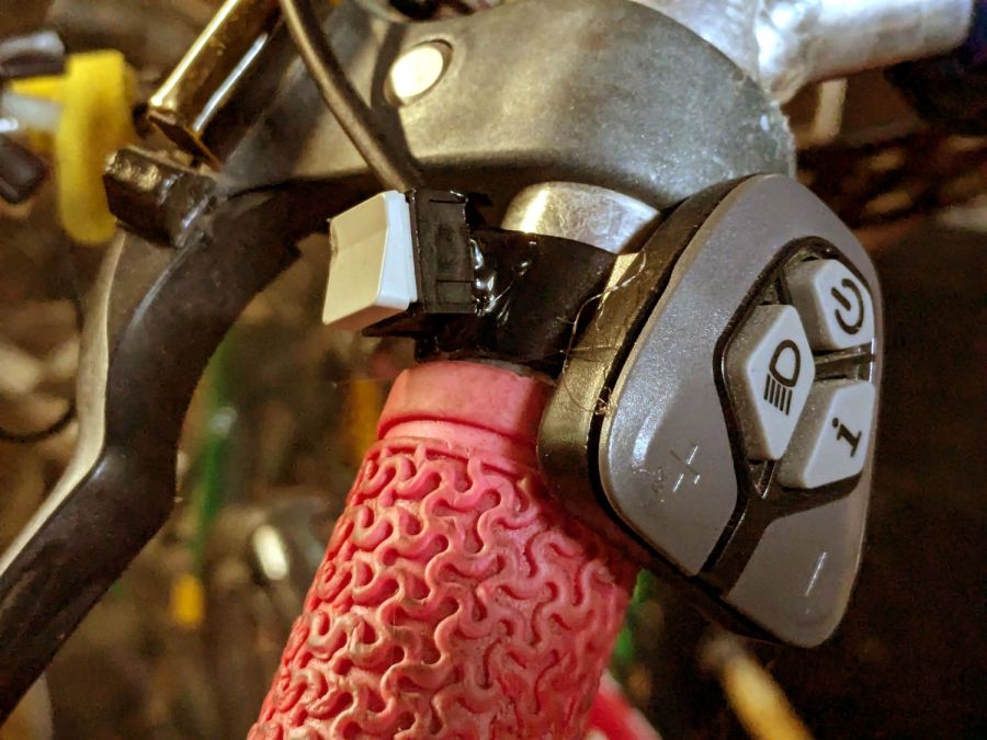
The replacement switch, also intended for indoor use on a keypad or some such device, pivots around the front edge and may be easier for her fingertip to activate:
New PTT Switch – installed
Hot melt glue seems vastly underrated for how wonderful a structural material it is.
If this one lasts five years, I’ll be perfectly happy.
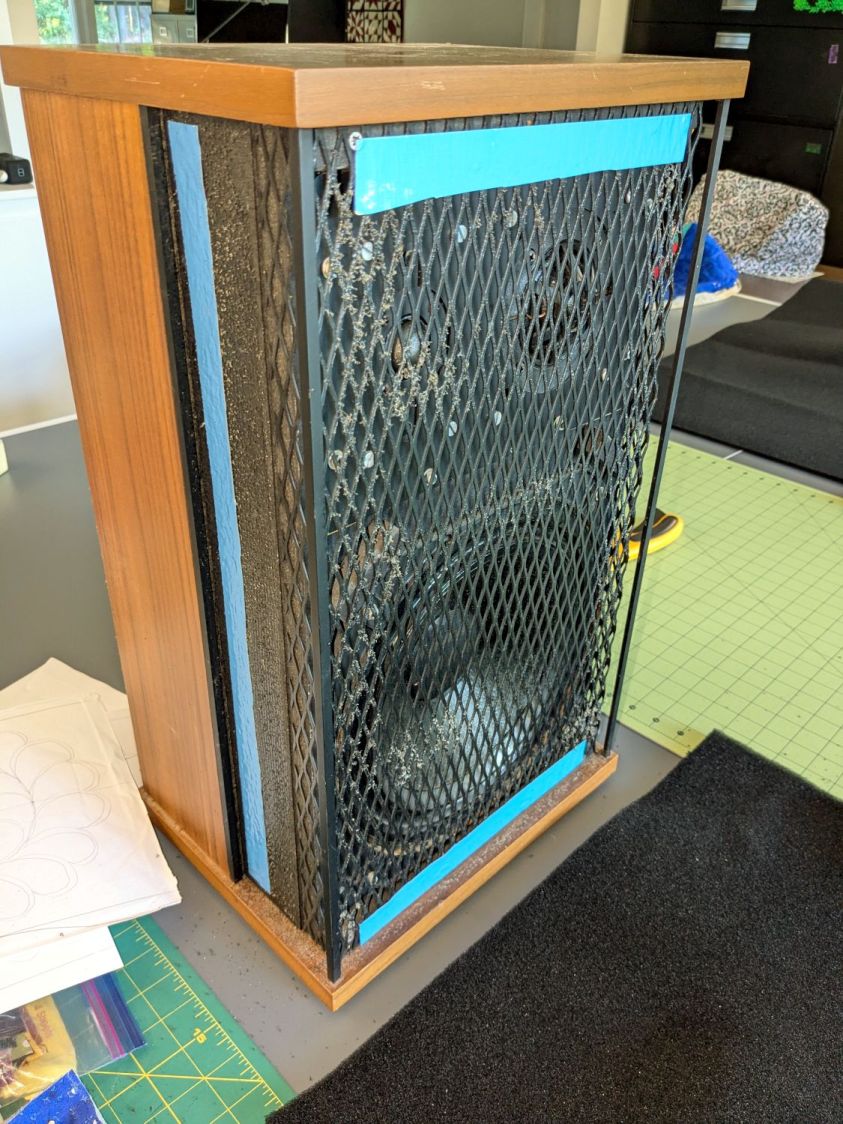
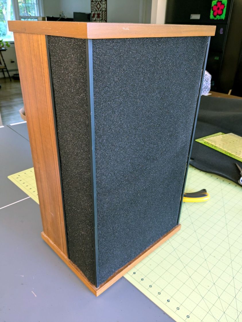
Having recently promoted a pair of Radford Tri-Star 90 speakers to the Sewing Room, it was time to make them presentable:
Radford Tri-Star 90 speakers – taped grill
The original foam grill covering had disintegrated and left fossilized adhesive over the metal gridwork. Being not much for historic accuracy, I used double-sided duct tape (the blue barrier film peels off) and stuck some allegedly acoustic foam in place:
Radford Tri-Star 90 speakers – re-covered
The foam is a single sheet wrapped around three sides and, after some whittling, measured 19.5 inches tall and 19.25 inches wide. The width surely depends on how snugly it’s stretched, so allow a bit more and trim to fit.
Duct tape probably isn’t the right adhesive for the job, but we’ll see how long it lasts. I really did not want to use spray glue and doubted my ability to slobber liquid stickum without oopsing the cones.
The speakers sounded great back in the day and they definitely sound much better than my deflicted ears can hear now. Mary thinks they’re OK and that’s all that matters.
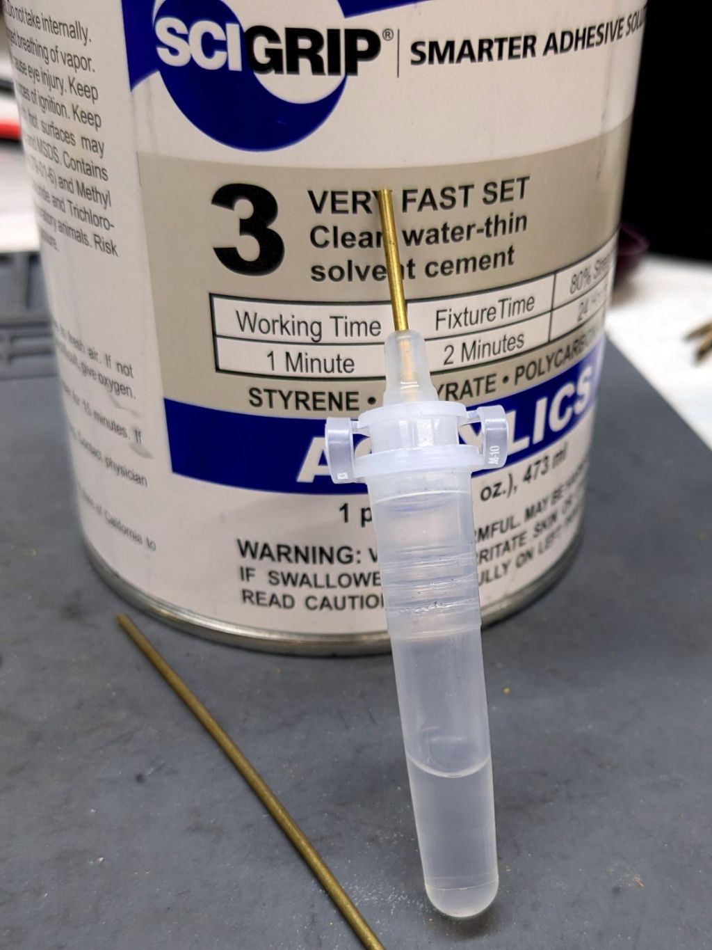
This seemed like a good idea for dispensing small drops of acrylic solvent while gluing spiders together:
COVID test Buffer Extraction Tube – adhesive hack
It’s the Buffer Extraction Tube from a COVID-19 rapid test kit with a short brass tube jammed in its dropper tip. The longer brass tube let me suck that dose of solvent into the tube without any of the hassle required to pour the liquid from a big can into a little tube.
Tell me you didn’t save those things because you thought they didn’t look like they might come in handy for something.
Well, that turned out to be a Bad Idea™, because whatever plastic that tube is made out of cracks when exposed to the hellish mixture in SCIGRIP #3 solvent adhesive. The tube didn’t dissolve or melt, it just cracked when you (well, I) squeezed the sides.
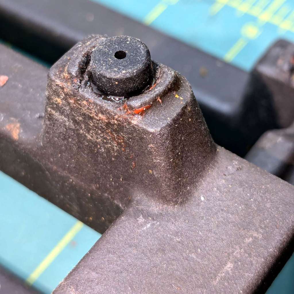
The Samsung range has ungainly cast-iron (or some such) grates that have long since worn out / lost their original Genuine Samsung rubber bumper feet. The grates had glued-on feet that looked very much like they belonged under something else, affixed with mystery adhesive that stuck firmly in some corners and let go in others:
Samsung grate – old foot
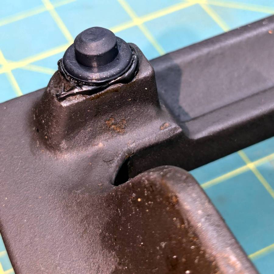
It seems Samsung no longer sells replacement feet, which may be an indication they don’t want customer complaints, so I got a bag of nominally compatible rubber feet from the usual source and broke out the cyanoacrylate glue:
Samsung grate – new foot
The red flecks are traces of a previous generation of adhesive, with the new cyanoacrylate peeking out around the base of the new foot.
The grates have holes for the stems of the feet, so in principle they have plenty of resistance to being shoved around. In practice, tipping the grates up to clean underneath them dislodged the feet with depressing regularity. The grates are too heavy and too awkward to remove and plunk somewhere else, which suggests this sort of range is better suited to a kitchen that’s never used or, perhaps, comes equipped with a support staff.
You’re supposed to use high-temperature adhesive and, in fact, the red flecks look remarkably like high-temp silicone gasket compound, but all the missing feet were along the back of the grates where the small & simmer burners live, so I figured cyanoacrylate was certainly worth a try.
When & if they fall out, I’ll know when they went in.
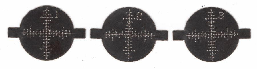
The dots just barely punch through the back side (open in a new tab & zoom for more dots):
Test paper – target patterns back side- 2024-07-03
The plastic coating chars and buckles with each pulse, but remains in place:
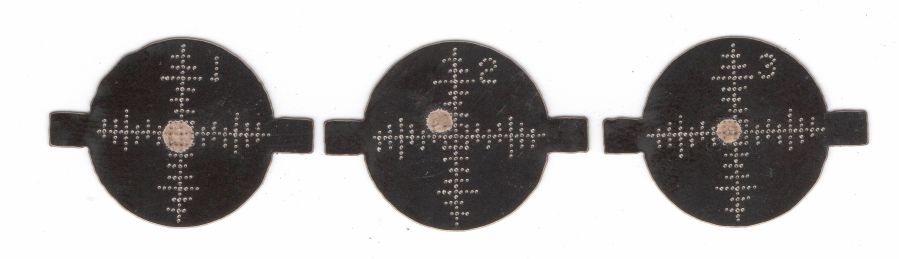
Test paper – 2 shot – uncleaned – 2024-07-03
Wiping the surface removes the loose coating / ash / debris to expose the underlying charred paper core:
Test paper – 2 shot – wiped – 2024-07-03
Those are two pulses marking the ends of each axis, so the machine remains well aligned after the fourth-quarter tweak.
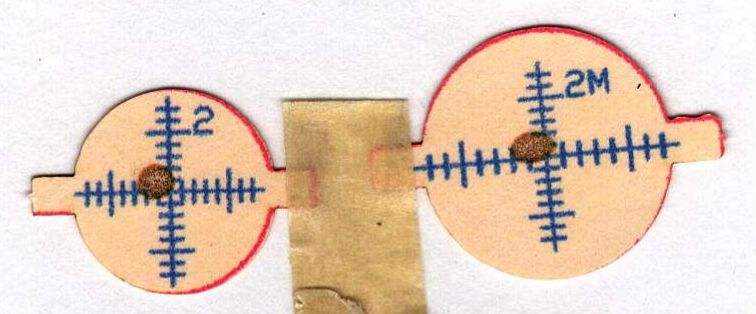
A single pulse shows the beam has a nice round shape with well-defined edges:
Test paper – 1 shot – wiped – 2024-07-03
In principle, the beam should be more intense toward the middle, but I suspect that’s beyond the paper’s ability to resolve the energy; the beam either burns through the coating or it doesn’t. In all those targets, the back surface of the paper remains undamaged.