Ed Nisley's Blog: Shop notes, electronics, firmware, machinery, 3D printing, laser cuttery, and curiosities. Contents: 100% human thinking, 0% AI slop.
The kitchen came with matched Samsung appliances dating back to 2018 and, on a frigid winter day, we piled the contents of the freezer on the porch and gave it a deep cleaning. While the empty freezer was cooling down from its adventure, I wondered:
Where were the condenser coils were located?
Did they need cleaning?
How does one do that?
The manual is strangely silent about even the existence of the coils, so evidently cleaning them wasn’t of any importance to Samsung.
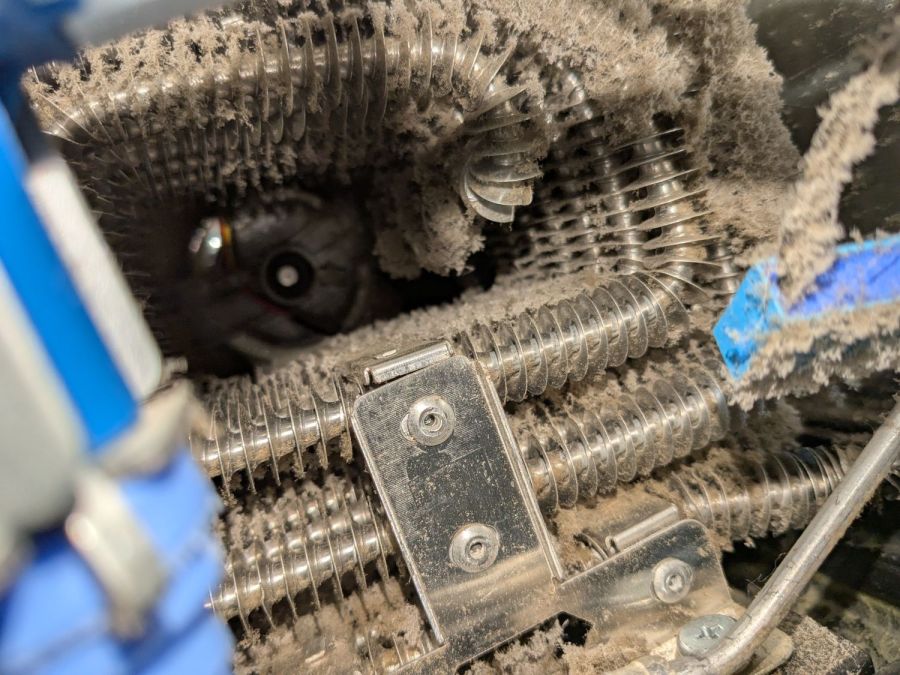
Rolling the refrigerator away from the wall just enough to get the phone camera down there suggests they exist and are in need of some attention:
Samsung refrigerator coils – first sight
Rolling the refrigerator out until the door handles met the countertop across the way let me climb over the counter and worm myself into the refrigerator-sized hole behind it, bringing along a screwdriver, the vacuum cleaner snout, and a few brushes.
Removing five screws released the back cover:
Samsung refrigerator coils – cover off
Looking into the intake end of those coils (on the right):
Samsung refrigerator coils – first intake view
So, yeah, I’m about to give them their first cleaning ever.
Five minutes of brushing fuzz, mostly into the vacuum, cleared a good bit of the exterior, but the interior needs more attention:
Samsung refrigerator coils – partial clean
Ten minutes later:
Samsung refrigerator coils – victory
Another five minutes:
Samsung refrigerator coils – intake cleaned
Making the coils cleanable and putting them where they could be cleaned were obviously not bullet-item goals for Samsung’s designers.
Although the coils are not perfectly clean, I don’t know how to get them any cleaner, despite knowing even a thin layer of fuzz kills the refrigerator’s much-touted energy efficiency. Perhaps blowing them off with compressed air, then cleaning a thin layer of dust off the entire kitchen, would help.
I think the refrigerator will be happier, at least for a while.
One of our regular walks takes us up the hill on Old Sivermine Place and, being that type of guy, I tend to look at the infrastructure. The LED streetlights along the road sit atop wood poles and are obviously retrofits. Placards on some poles announce “277 V”, which means they’re fed from one leg of a three-phase 480 V wye service, making their casual mid-air wire-nut spliced connections seem … inappropriate.
Anyhow, they’re supposed to look like this:
LED streetlight – D
In reality, having multiple emitters comes in handy:
LED streetlight – C
Typical 12 V systems have parallel strings of three LEDs in series, so you (well, I) often see automobiles with three adjacent dead LEDs. That turned out to be true with the 15 V (-ish) LEDs in the HQ Sixteen machine I’ve been refurbishing.
These streetlights apparently have individual LED drivers, allowing single LEDs to go dark without affecting the rest. This one has five deaders, so the rot is spreading:
LED streetlight – B
There seems no pattern to the failures:
LED streetlight – A
Those fixtures are in order from the top of the hill downward.
Each light has its own photosensor to decide when to turn on. We don’t go walking after dusk, but at least one light will always be glowing brightly in middday; the sensors aren’t doing well, either.
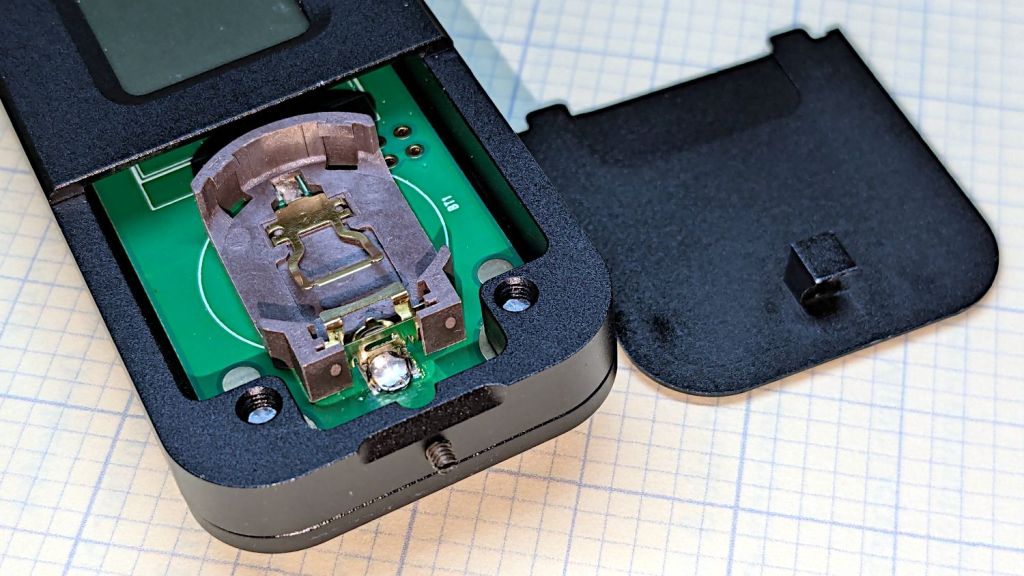
The manual does not exactly match the hardware. In particular, “so users won’t need any tools to replace the battery” is incorrect:
HLP-200B – battery lid screw
Until you loosen the M2 setscrew below the finger notch a couple of turns, “Use just fingers to remove the battery cover” will merely scuff your fingerprints. Apply a 1.5 mm or 1/16 inch straight screwdriver bit with no more than finger torque and, after two or three turns, the lid comes free.
The meter arrives without a battery, so you passed the first test.
Despite the “another screw hold (M4) is added”, there’s only one tapped hole in the case, as visible in the back panel photo. Seen from the front, it’s above the four digit LCD.
Operation is at best awkward and at worst hazardous:
Press the blue button to turn it on and hear a beep
It’s ready to measure within three seconds
Hit it with the laser beam until it beeps
The LCD shows the power for six seconds
It shuts off with a beep
Bonus: If the meter doesn’t detect any energy, it shuts off 20-ish seconds after the button press
Minus my power ears, the beeps are completely inaudible.
The meter is sensitive enough to respond to weak heat sources like LED bulbs and even fingertips, so you can test it without firing the laser. The numeric value shows the power from a CO₂ laser beam dumping an equivalent amount of energy into the sensor:
HLP-200B – finger heat response
The sensor target is 20 mm OD, although the instructions remind you to “Ensure the laser is emitted to the center of the sensor”. I suspect hitting the sensor with a focused laser spot will eventually damage the surface.
Making a real measurement requires:
Set the Pulse button for continuous output
Set the power level
Defeat the lid interlock switch on the laser cabinet
Push the blue button on the HLP-200B
Quickly position the meter target accurately in the beam path
Hold down the laser Pulse button
Freeze in that position until the meter beeps
Release the Pulse button
Quickly reorient the meter and read the display
I have a visceral reluctance concerning safety interlock overrides, misgivings about poking my head inside the cabinet, and no yearning to put one hand near the beam line with the other on the console. Yes, I have known-good laser safety glasses.
The meter generates plausible results for the (claimed) 60 W tube in my machine, but further tests await conjuring fixtures to keep various irreplaceable body parts out of harm’s way.
Mary’s Handi-Quilter HQ Sixteen is new-to-her, but it’s had two previous owners over the past two decades. Neither of them reported any particular problems with it, but it now displays an intermittent Motor Stall error on its LCD panel(s). This post summarizes what I know and guesstimate to date.
The Motor Stall error happens at the first motor motion after turning the machine on, upon pressing either the Needle Up/Down or Start/Stop button on the handlebars. The motor does not move at all during the slight pause between pushing the button and seeing the error message. Pressing either button again clears the error message, although I (obviously) do not know if doing so affects any of the microcontroller’s internal status flags; the error dependably reoccurs after doing so.
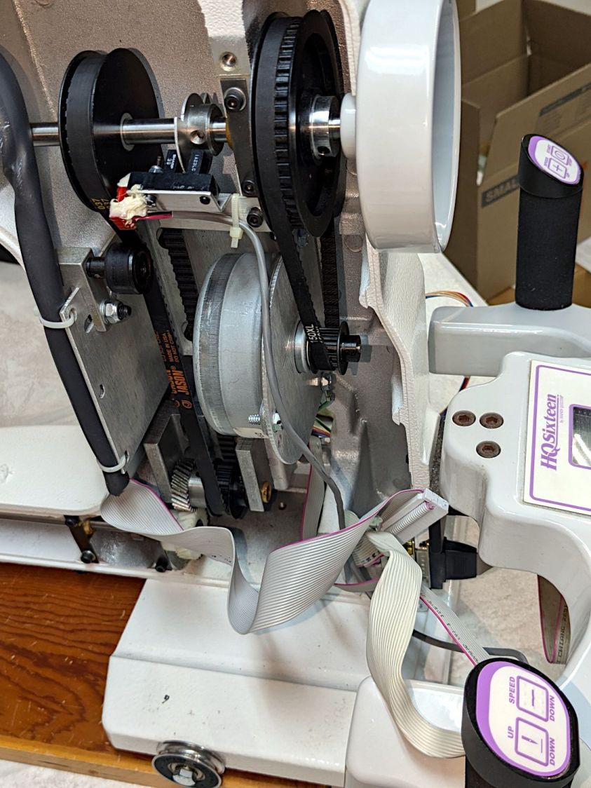
A separate sector disk on the machine’s shaft sets the needle-up and needle-down positions through an optointerrupter:
The white silicone snot on the interrupter connector is original.
After the error occurs, slowly turning the machine handwheel while pressing either button generally prevents the error message from reappearing, suggesting the “stalled” signal from the motor is working and the signal reaches the microcontroller.
Turning the handwheel while pressing the Up/Down button does not produce an error message due to the “motor” not stopping at the appropriate edge of the sector disk.
The InterWebs suggest a thread jam, crud in the bobbin, and a needle crash can trigger a Motor Stall. When the machine is operating correctly, running it at slow speed and stopping the handwheel by hand (it has little torque) triggers the Motor Stall error message. However, the controller will clear the message and the machine will resume normal operation thereafter.
Conversely, when the Motor Stall error occurs at startup, it remains absolutely consistent and survives the usual “Reboot that sucker!” power cycle. Leaving the machine turned off and untouched for a few hours / overnight may reset whatever is wrong, after which it will run normally through many power cycles.
Long enough, indeed, to finish an entire practice quilt over the course of several days:
HQ Sixteen – remounted handlebars in use
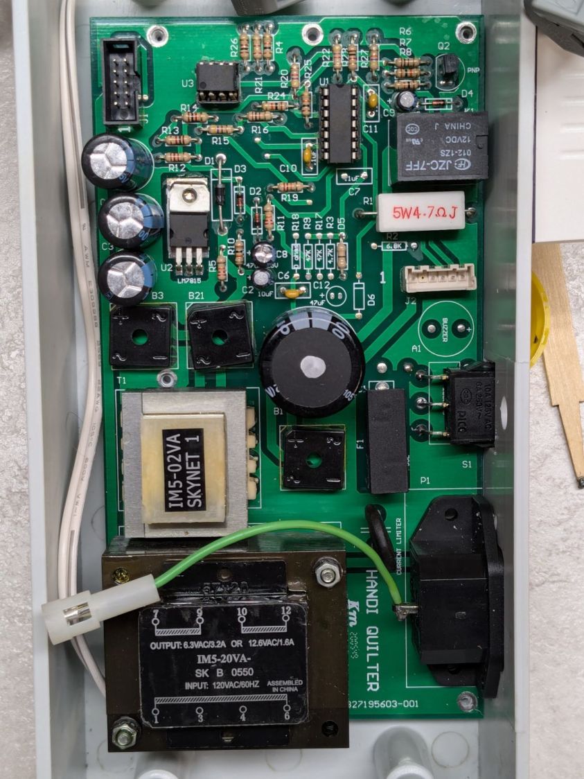
The component side of the power supply / motor interface PCB inside the pod:
Power PCB – components
Connections:
Microcontroller board at top left
BLDC shaft motor middle right
Frame ground on green wire
AC power input on the IEC jack
Power switch just above IEC jack
A closer view of the ICs:
Power PCB – IC detail
Some initial thoughts on the circuitry, without detailed PCB tracing …
Although the date codes suggest it was built in 2005, the electrolytic caps show no signs of The Plague.
The TO-220 package is a classic LM7815 regulator with its tab soldered to a copper pad. No extensive copper pour on either side serves as a heat spreader.
The 8 pin DIP is an MCT62 dual optoisolator handling the motor speed control and stall sense feedback.
The big transformer at the bottom sends raw DC to the microcontroller board through B3 and J1, filtered by two of the electrolytic caps along the left edge. I think the low side remains isolated from the power board’s common, thus isolating the microcontroller from the AC power line.
The Skynet (‽‽) transformer produces +15 V through the 7815 regulator and B21 bridge, filtered by the middle electrolytic cap along the left edge of the board. All of the circuitry on the board uses that supply, with the low side as circuit common.
The 160 VDC (!) supply for the BLDC motor comes directly from the AC power line with no isolation through the Current Limiter PTC, the B1 bridge, and the hulking electrolytic cap in the middle of the board. The relay in the upper right energizes just after the power goes on, connecting the motor power return lead to circuit common through the 5W 4.7Ω sandbox resistor. The “common” side of B1 is, thus, not connected to the neutral side of the power line and, more importantly, none of the circuitry on the PCB is isolated from the power line.
As a result, casually clipping a line-powered oscilloscope’s “ground” probe lead to what’s obviously the circuit “common” will, in the best case, turn the ground lead into a fuse. I’ve done this exactly once, deep in the past, with a Tektronix 7904 mainframe oscilloscope priced (with plugins) somewhat higher than the house we owned at the time; suffice it to say I learned from that mistake.
I think (part of) the LM339 quad comparator determines the relay’s time delay, perhaps in response to a signal from the microcontroller after it wakes up.
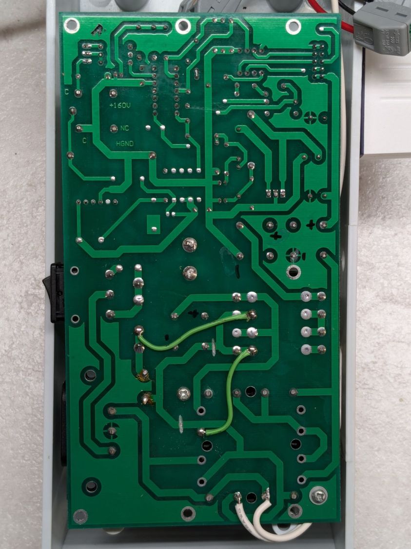
The solder side of the same board:
Power PCB – solder
The two green wires and trace cuts are original, apparently to power just B21 (the motor supply) from the AC line through the fuse + PTC, with the two transformers connected directly to the AC line through the switch & fuse. The two white wires on the bottom go to the power supply I added for the Chin Light; the Motor Stall problem predates that modification and the handlebar relocation.
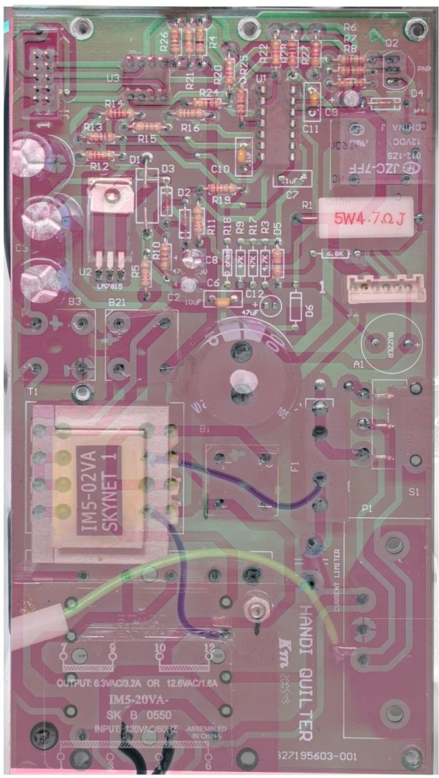
After cleanup / squaring / tweaking, the two images combine into an X-ray view:
Power PCB – overlaid
With all that in mind, some possible causes …
Taking the power supply and microcontroller pods off the machine and poking all the obvious spots has no effect. Not taking them off and not touching the machine may resolve the problem by the next day, after having it fail consistently during most of the previous day.
The motor label says DR-8538-937, which does not appear anywhere online, so this must be a unique Handi-quilter part. An overview of DR-8538 motors suggests they’re available with a variety of windings, none of which match the machine’s 160 VDC supply voltage. Because the PCB has no high-voltage / high-current switching components, other than the bulk DC supply, the motor contains the BLDC control & drive circuitry. The closest matching catalog page conspicuously does not identify the motor wiring connections.
This figure from another catalog suggests the motor accepts a DC speed control and outputs an open-collector “locked rotor” signal:
BLDC DR-8538-555 Motor pinout
The Handi-Quilter DR-8538-937 motor has five leads in the J2six pin header which could match thusly to the four pins in the figure:
Pin 1 = 160 VDC (pin 1 → 24 VDC )
Pin 2 = missing
Pin 3 = common (pin 2 → GND)
Pin 4 = ? (pin 3 → -On)
Pin 5 = ? (pin 4 → Lock ?)
Pin 6 = +Buzzer and elsewhere (?)
This will obviously require reverse engineering the schematic from the PCB traces, thus the X-ray view above.
The most obvious cause of a Motor Stall would be a defective / failing motor. Through a cosmic coincidence, a motor “removed from a working HQ Sixteen” was available on eBay when I looked. It behaves no differently than the original motor and, while it’s possible both motors have the same internal fault, that seems unlikely. The “new” motor now runs the machine, with the original motor neatly bagged in a box against future need.
Re-seating all the ICs on both boards produced ominous crunching sounds, but no improvement. Wiping DeoxIT on the leads of the two ICs on the power board had no effect.
Replacing the 10-conductor ribbon cable between the two boards had no effect. I knew I was saving those insulation displacement connectors for a good reason.
The MCT62 optoisolator has a minimum current transfer ratio of 100% at 10 mA diode current. A gimmicked test setup produced 8 mA in the output transistors with 6 mA through the diodes, which seems good enough.
The relay clicks audibly, even with my deflicted ears, suggesting that it’s working, although we have not had a motor failure while we were listening. It is possible the contacts are intermittent, letting the relay click without making contact; we’re now listening intently.
The machine lives upstairs, my instruments live in the basement, and I am unwilling to lug an awkward and invaluable 50 pound lump between the two. The next time the motor stalls, I must dismount the power pod from the side of the machine, haul a bunch of gear (including an isolation transformer!) upstairs, and probe various points while it remains defunct.
Things to find out:
What each of the five motor wires do
Discover the circuitry handling the optoisolator signals
What drives the relay?
Even though the machine ran perfectly for a week, a fundamental Debugging Rule applies: If you didn’t fix it, it ain’t fixed.
You’ve just seen more tech info on the HQ Sixteen than previously existed on The InterWebs.
These Dirac-delta pulses seem to be a new thing, with one “reader” hitting many posts, rather than many readers hitting a single post. I can’t tell if it’s a new way for search engines to scan pages or an entirely new algorithm doing the scanning.
Should you run across another blog with similar verbiage, you know where it started …
A flurry of alerts informed us about charges on an “inactive” credit card account: someone started using my card from a joint account with Mary. Our two cards have different numbers and security codes, although they produce charges to the same account.
The account was inactive for a simple reason: I’d never taken my card out of its mailer and never bought anything with that number. It was activated when Mary turned on her card, although it still carries that sticker:
Invalidated credit card
The customer service agent discovered Amazon had already issued a refund, so apparently the transaction tripped their fraud monitors.
He canceled that number and I’ll get another card, which I intend to continue not using, in a few days.
What I do not understand: how did my card number and security code end up in play, given that I never used it? AFAICT, the only two places that number appears are on the card and in the issuer’s database.
Do you know how such things work?
A casual web search for the (now invalidated) credit card number produces no hits. The simplest explanation: search engines don’t return results for sixteen digits resembling a credit card number.
Verily: just because you’re not paranoid doesn’t mean they’re not out to get ya!
Here’s what I think is going on, referring to the 4×8 foot (!) machine in that discussion and lightly edited to improve readability & fix minor errors …
Mirror 1 alignment gets the beam parallel to the Y axis, averaged over the gantry travel between front and rear. The path length variation on your machine is four feet.
Mirror 2 alignment gets the beam parallel to the X axis, averaged over the laser head travel from left to right. The path length variation on your machine is eight feet.
When the laser head is in the left rear corner, the total path length is maybe a foot or two. When it’s in the front right corner, the total path length is upwards of twelve feet.
The “Fourth Corner” problem comes from a slight angular misalignment of Mirror 1, because you (and I and everybody) must set it with a maximum path length around four feet (Mirror 1 to Mirror 2 with the gantry at the front end of the machine). But with the laser head in the right front corner, the path length (Mirror 1 to Mirror 3) is three times longer, so the error due to a slightly mis-set angle at Mirror 1 is correspondingly larger.
A tiny tweak to Mirror 1 changes the spot position at Mirror 2 by very little, but moves the spot at Mirror 3 by much more due to the longer path length.
Tweaking Mirror 1 cannot compensate for a warped machine frame, but it will get the beam alignment as good as it can be made.
The next point of contention was my “middle of the mirror” suggestion. AFAICT, the spot burned into the target at each mirror marks only the useful part of the beam with stray energy in a halo around it. Centering the spot keeps that stray energy away from the mirror mounts, so it doesn’t cause unnecessary heating. This will be particularly important with a high-power laser.
Angular adjustment of each mirror puts the beam parallel to the axes, but cannot also center it on the mirrors. After it’s aligned, the path from the laser tube through the nozzle depends on the position of the tube relative to the nozzle: moving the tube up/down and front/back moves the beam position on the mirrors and through the nozzle, but (in an ideal world) doesn’t change the angular alignment.
So after aligning the beam parallel to the axes, you must move the laser tube, the mirrors (up/down left/right front/back), and maybe the laser head to center the beam in the mirrors and also in the nozzle. Because we don’t live in an ideal world, moving any of those pieces wrecks their angular alignment, so it’s an iterative process.
The goal is to reach this point:
Beam Alignment – Mirror 3 detail – 2023-09-16
Those are five separate pulses, one each at the four corners and center of the platform.
The beam then goes pretty much through the center of the laser head and lens: