Ed Nisley's Blog: Shop notes, electronics, firmware, machinery, 3D printing, laser cuttery, and curiosities. Contents: 100% human thinking, 0% AI slop.
Every few days this month, a Korean company has sent identical spam email messages to a series of plausible, albeit unused, addresses at softsolder dot com:
As a forward-thinking hotel, we know you prioritize cleanliness and guest satisfaction. That’s why we’re excited to introduce Harington, an advanced sterilization device designed to provide 99.99% bacteria and germ elimination for toilets, ensuring the highest standards of hygiene for your guests.
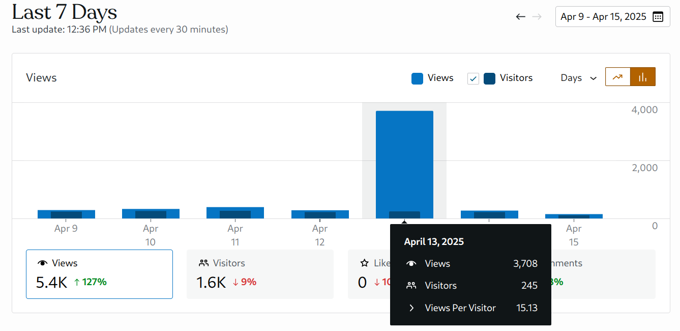
Typically, every day two or three hundred visitors read three or four hundred posts, about 1.4 posts/viewer. Nearly 4000 views from the same number of visitors is unusual. The whole blog has just over 5200 posts; perhaps they don’t want really old content.
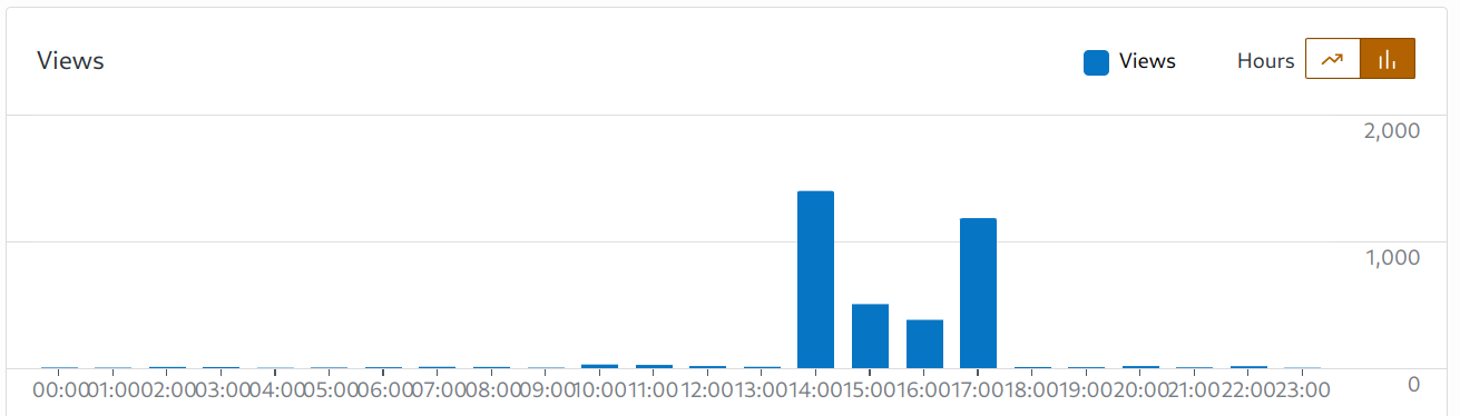
A look at the timing suggests what happened:
Site stats – 2025-04-13 detail
My guess: WordPress throttles aggressive scraping, so the program backed off for a couple of hours before finishing the job.
Long ago, a magazine editor told me I have the strongest writing voice he had ever encountered, so when an AI uses my blog as its training set the results should be obvious.
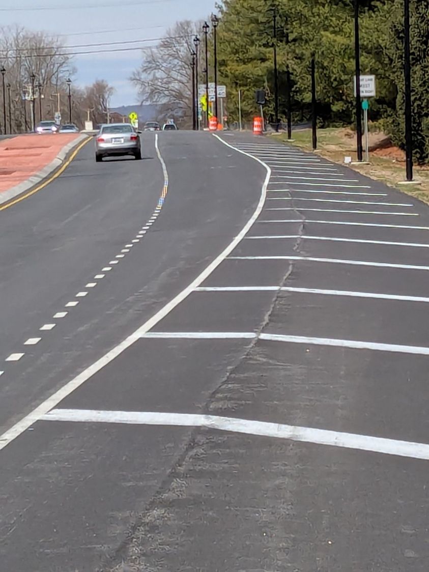
The previous layout of Rt 376 had two lanes approaching the Raymond Avenue intersection from the south (from the right in this rotated & ruthlessly contrast-blown Google Maps screenshot):
Rt 376 at Raymond – prior two-lane striping
The right lane is marked Only ↱ for the Raymond intersection, starting just past the Vassar Security Office entrance in the top middle of the screenshot.
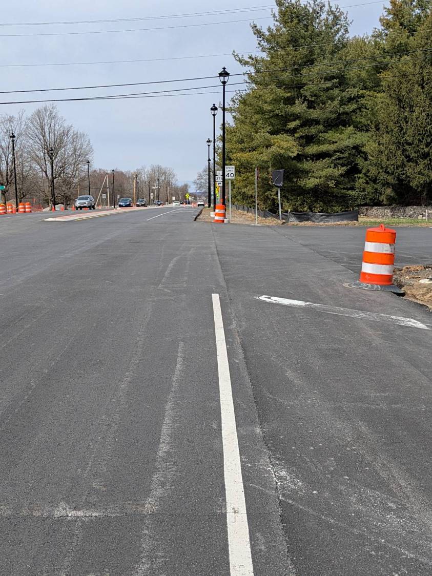
Given this preliminary striping with faded Only ↱ markings, one might assume a similar lane layout is in effect for the new traffic circle at the intersection:
Vassar Security Office Lane – A
The lighting poles may seem snugly placed, but not too much out of the ordinary:
Some drivers seem concerned at this point:
Vassar Security Office Lane – C
With any luck, they can swerve back into what is the only lane going all the way to the circle, because the right lane is dedicated to Vassar Security Office traffic:
Vassar Security Office Lane – D
If you happen to be walking southbound, toward the traffic, in the middle of the shoulder beyond the turn lane, you will look that driver directly in the eye, as happened to me while walking back from Mary’s garden.
As I mentioned last week, my money says that first lamp post, the one with the barrel guarding it, won’t survive the year.
Given the utter lack of pedestrian facilities (f.k.a. “sidewalks”) south of the circle, I can only hope the road furniture will absorb all the damage / fatalities.
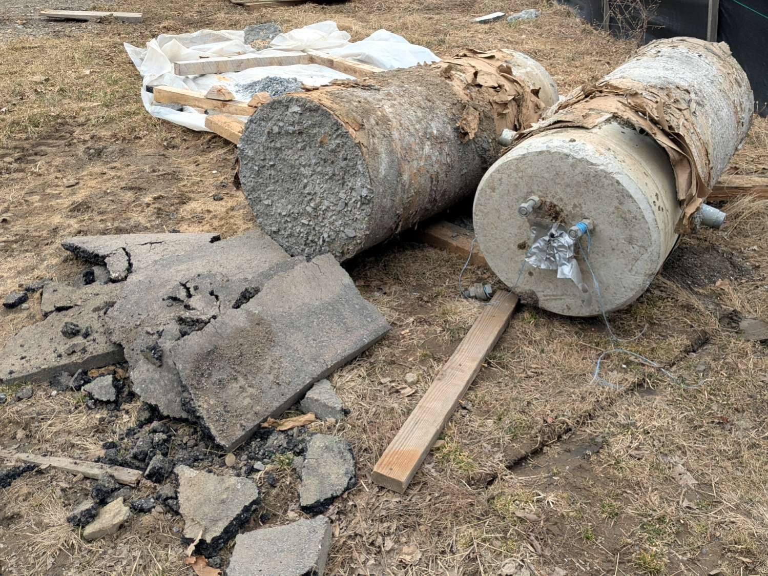
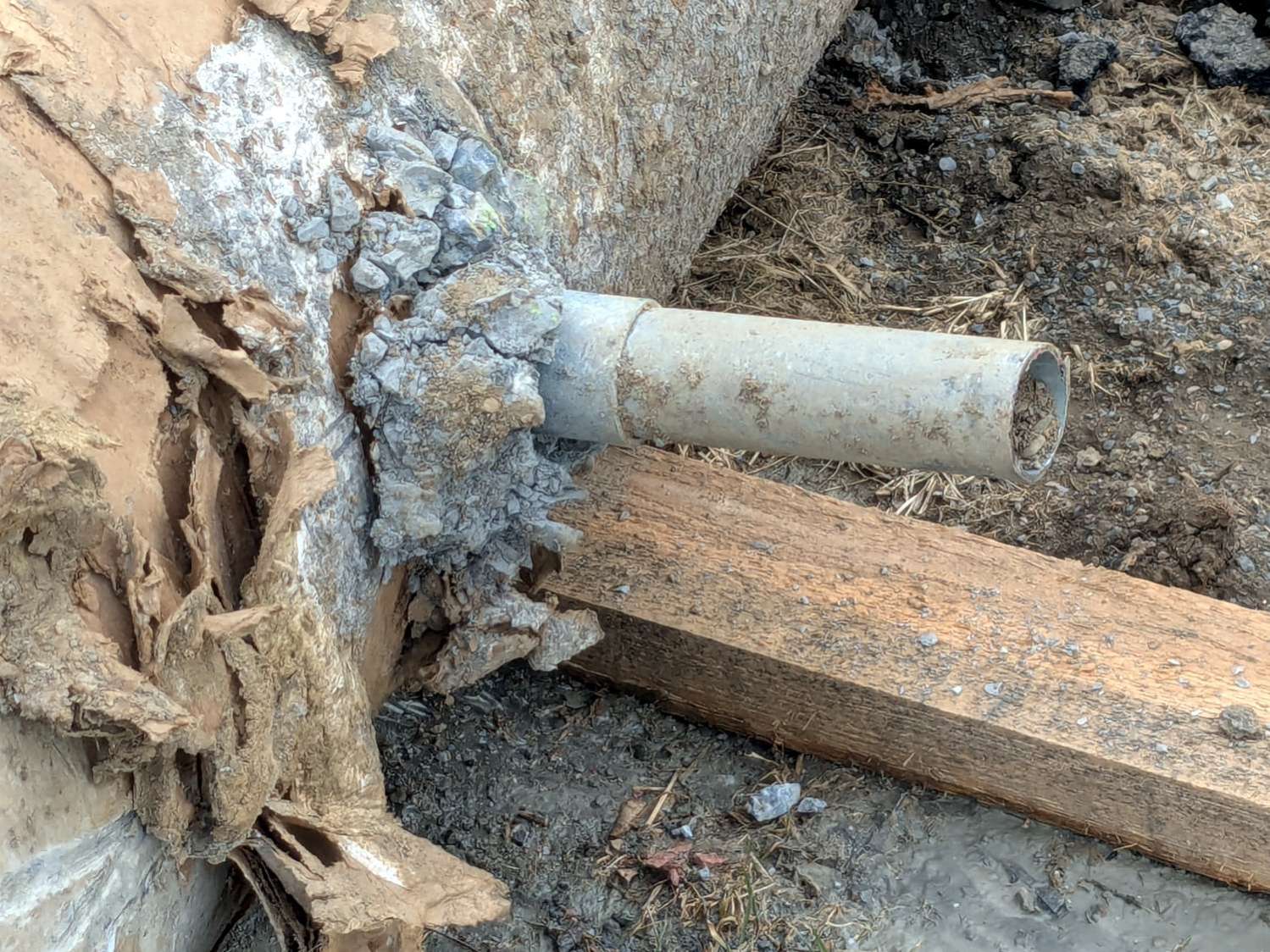
Apparently they excavated around the smashed bases and sawed off the conduits:
Street Lamp Base – sawed conduit
Then they yoinked the concrete cylinders, installed new bases, re-connected the conduits, cast more concrete, and installed the posts:
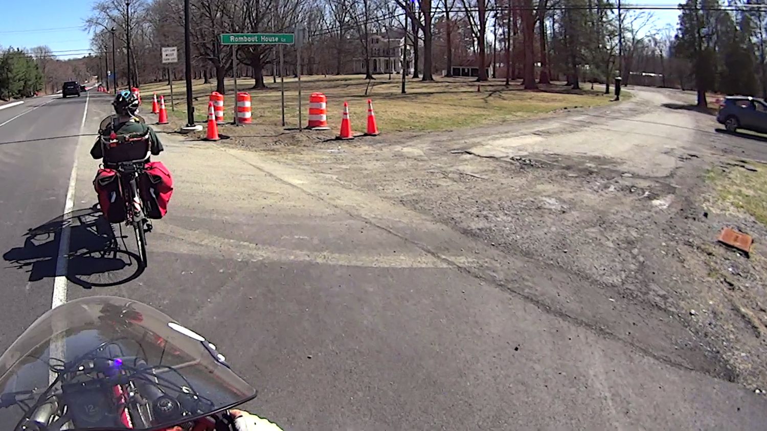
Street Lamp Base – Rombout House Ln – detail
I think the two “Signal” box covers flush with the surface on either side of Rombout House Lane lie just beyond the edges of what will eventually be the repaved road at the intersection.
Street Lamp Base – Rombout House Ln – overview
Given how much damage the base at that intersection encountered, my visualization of the Cosmic All says that pole will not survive the year unless they install a few well-spaced bollards.
There’s another pole on the other side of the road I expect will have a full-on collision, too.
I always suspect there’s a reason behind a missing price label on a shelf, so I waved a half-gallon of milk under a nearby price scanner:
Shop-Rite Scanner FAIL
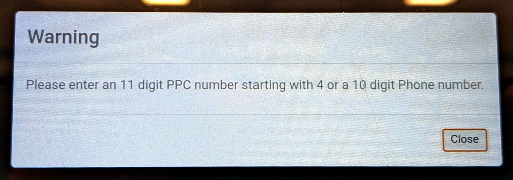
If you’re thinking that white rectangle doesn’t look like a price, you’re right:
Shop-Rite Scanner FAIL – Warning pop-up
A 10 digit Phone number?
I’m don’t know what a “PPC number” is, although the UPC on the milk carton seems perfectly normal:
Shop-Rite Scanner FAIL – offending bar code
Admittedly, the number starts with a zero and has 12 digits, so it’s definitely not what the price scanner wants. On the other paw, why is a price scanner not looking for a UPC?
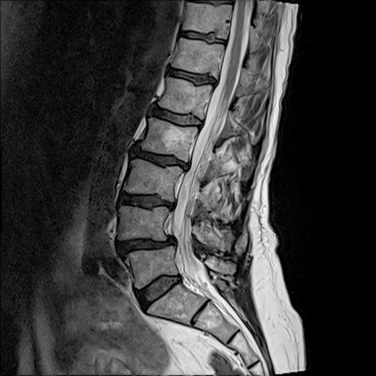
I asked for the images from recent X-ray and MRI sessions, whereupon a CD arrived in the mail. Popping it into my desktop Linux box produced this directory listing:
ll /run/media/ed/Feb\ 21\ 2025/
total 146M
dr-xr-xr-x  2 ed   ed    136 Feb 21 13:14 ./
drwxr-x---+ 3 root root   60 Mar  2 13:40 ../
-r--r--r--  1 ed   ed   146M Feb 21 13:14 -NISLEY-DMBG8yMQcf8qXcVj.iso
It seems whoever / whatever produced the CD copied the ISO image to the CD, rather than burning the ISO directly to the CD. As a result, the CD has one file.
Raise your hand if you’ve never done that.
Well, I was going to save the CD as an ISO file anyway, so I just copied it to the file server.
Attempting to mount it produces an odd result:
sudo mount -o loop "-NISLEY-DMBG8yMQcf8qXcVj.iso" /mnt/loop/
[sudo] password for ed: <make up your own>
mount: failed to set target namespace to ISLEY-DMBG8yMQcf8qXcVj.iso: No such file or directory
Oh, right, starting a filename with a leading dash is never a Good Idea™.
Rename it:
mv -NISLEY-DMBG8yMQcf8qXcVj.iso NISLEY-DMBG8yMQcf8qXcVj.iso
mv: invalid option -- 'N'
Try 'mv --help' for more information.
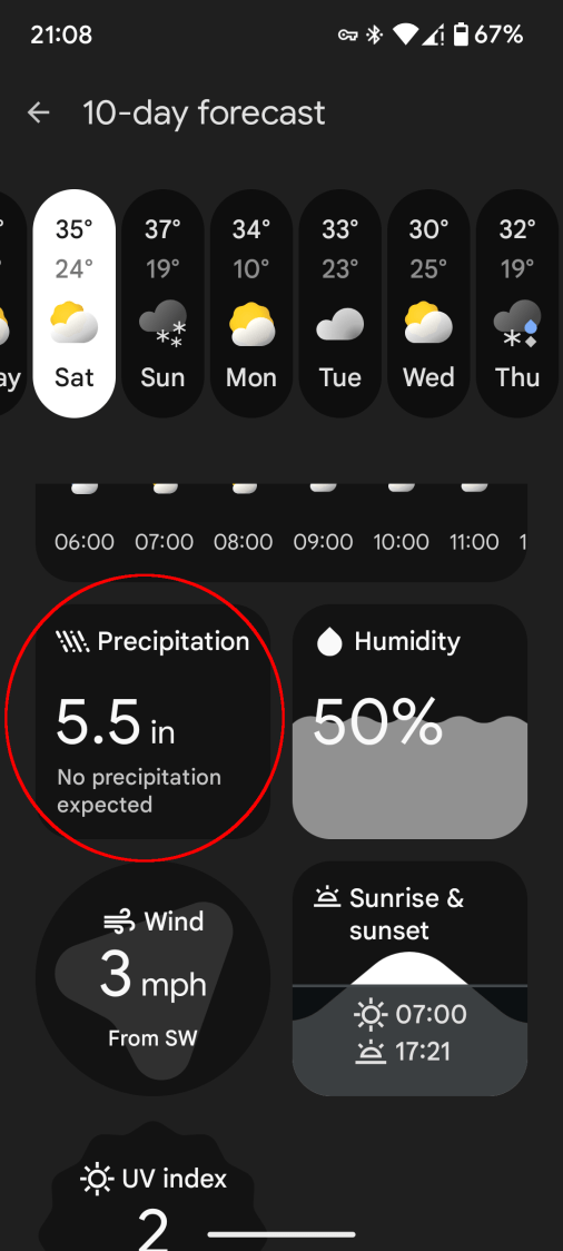
We didn’t get half a foot of any precipitation that day.
That is apparently the “Pixel At a Glance” app using info scraped from weather-dot-com. The other Google Weather app, the one that may or may not still have the Weather Frog, scrapes info from noaa-dot-gov and seems somewhat less uncoordinated.
The two apps generally disagree on what kind and how much precipitation will occur, sometimes absurdly, and rarely agree with the official National Weather Service forecast.
Sometimes the forecasts have not converged by the time the weather arrives outside the window.