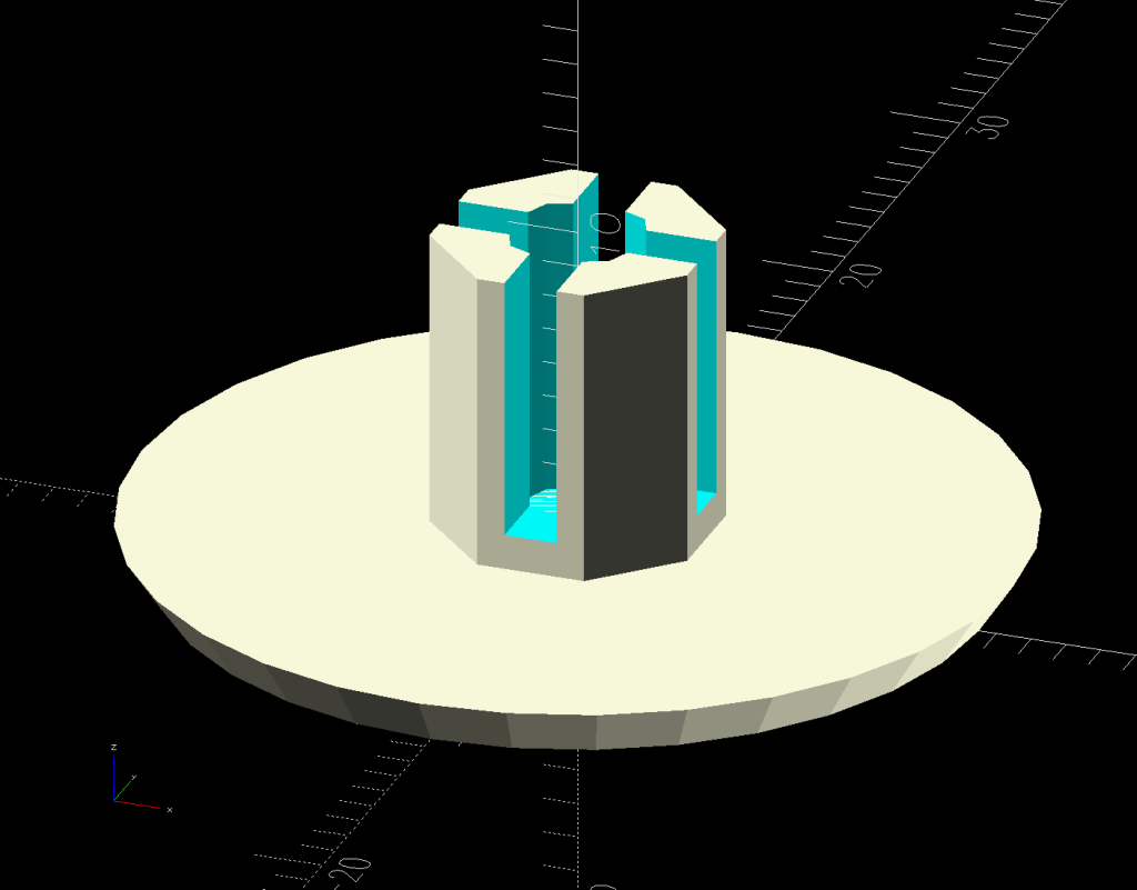
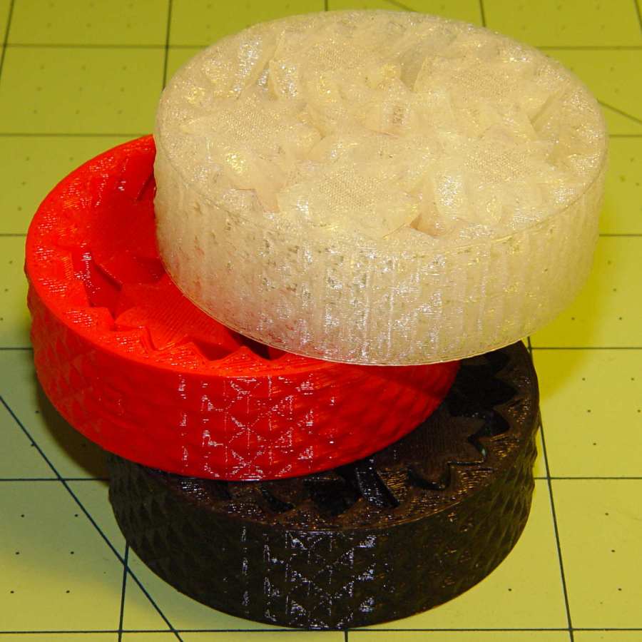
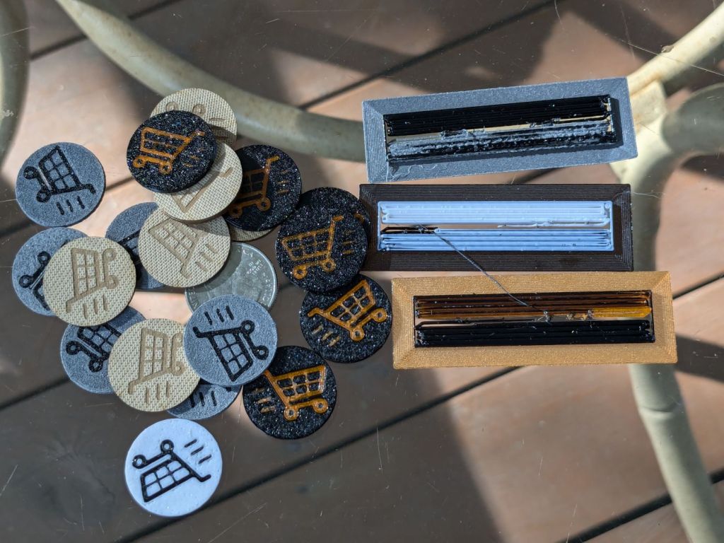
A special request came in for cart coins with a handle:

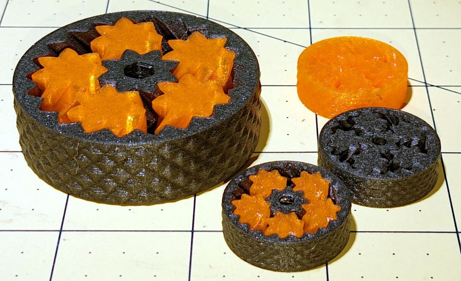
That’s in gray PETG-CF (carbon fiber) with Extrusion Multiplier = 1.0 based on the Pill Tube tests and and slightly lower temperatures based on the temperature tower. It definitely looks overstuffed and so does the Wipe Tower for that set of six coins:

The orange threads off to the right suggest something went terribly wrong with the top layer, which corresponds to the somewhat recessed cart image in the coin, but there were no other symptoms.
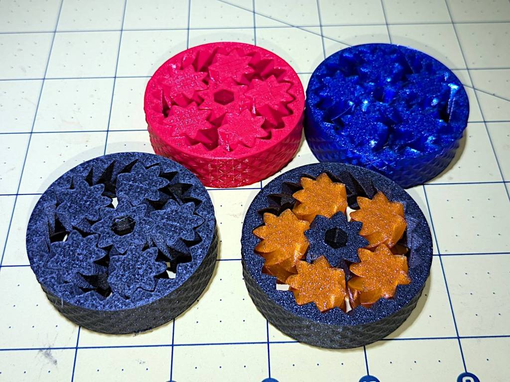
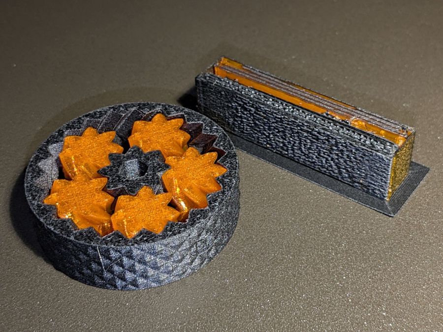
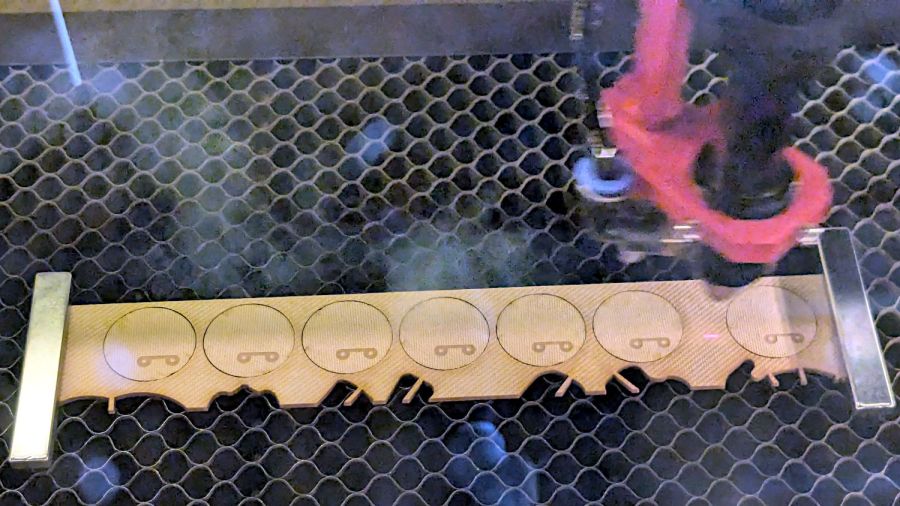
All six of the next set failed completely:

Apparently the nozzle hit the clotted gray filament in the Wipe Tower and stalled the X axis motor:

That suggests the same thing happened to the first set during the last pass over the Wipe Tower, causing a less obvious failure.
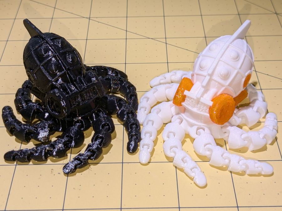
Setting the Extrusion Multiplier = 0.65 produced a better result:

Albeit with a slightly understuffed top layer:
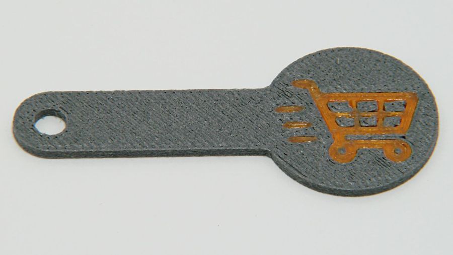
But not by much:

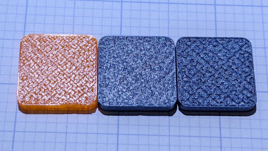
So the answer depends slightly on the PETG-CF filament color, but not by enough to justify defining three different filament types.
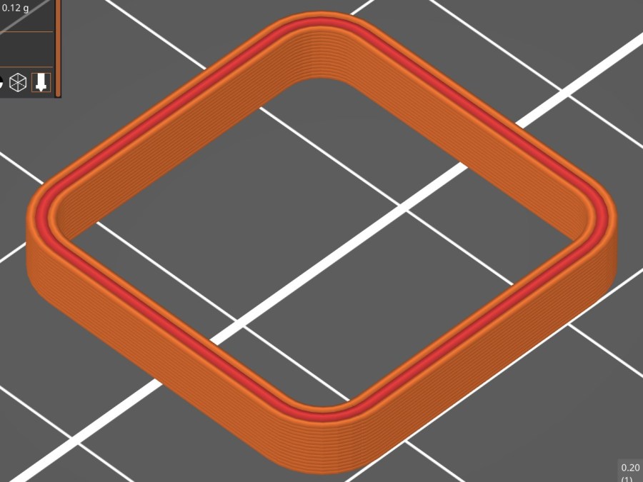
Cart coins are essentially solid plastic layers with no empty infill, so they have nowhere for excess filament to hide. The Wipe Tower should have plenty of room, but even at EM=0.65 the tower looks overstuffed on the side with the carbon fiber purge lines:

The default 110% line spacing in the tower seems too small for PETG-CF, so I’ll increase it to 150% to see if that reduces the clumping.
Judged by the surface finish, a 0.65 Extrusion Multiplier is too low, so I’ll try a set of coins at 0.80.