The Smell of Molten Projects in the Morning

Ed Nisley's Blog: Shop notes, electronics, firmware, machinery, 3D printing, laser cuttery, and curiosities. Contents: 100% human thinking, 0% AI slop.

Tag: Memo to Self

Maybe next time I’ll get it right

  • Vacuum Tube Lights: Triode

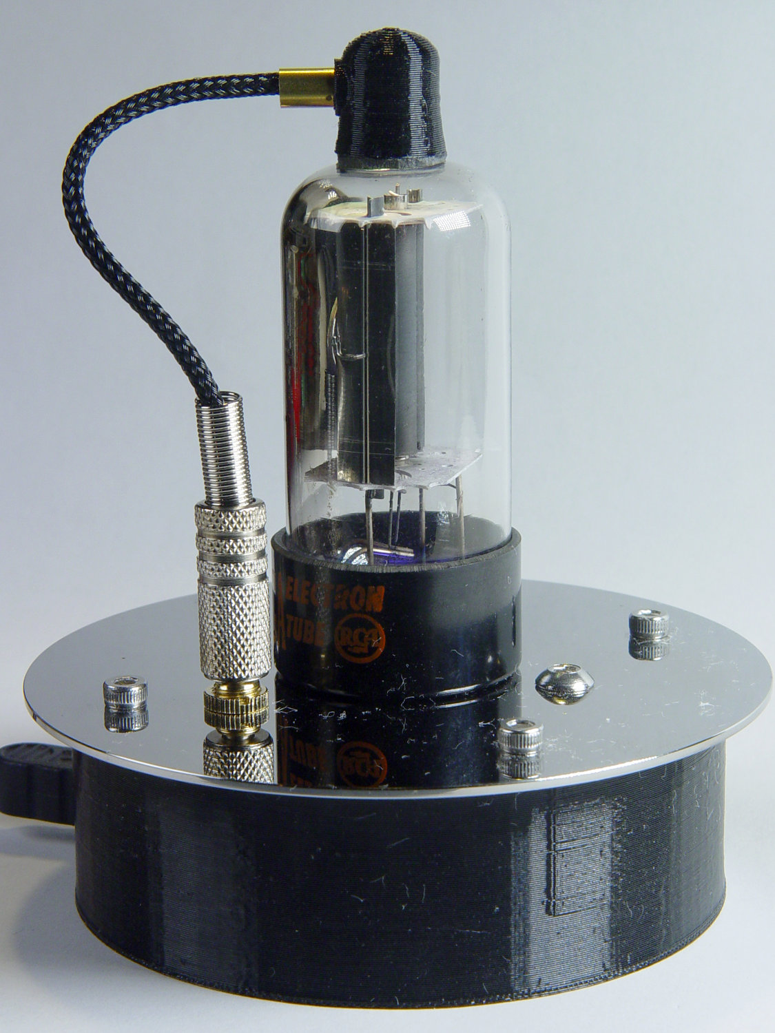
    With the wrecked 5U4GB safely in the trash, I popped a smaller, somewhat less stately triode from the Big Box o’ Hollow-State Electronics and wired it up with a pair of SK6812 RGBW LEDs:

    Triode - Purple-green phase
    Triode – Purple-green phase

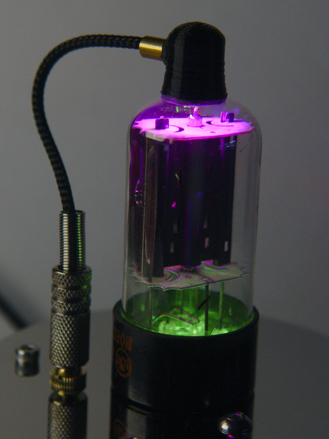
    The tube’s markings have long since vanished, but, at this late date, all that matters is an intact glass envelope!

    After two years, the ordinary white foam tape holding the knockoff Arduino Nano lost most of its sticktivity and easily popped off the 3D printed base:

    Triode - Nano PCB - white strips
    Triode – Nano PCB – white strips

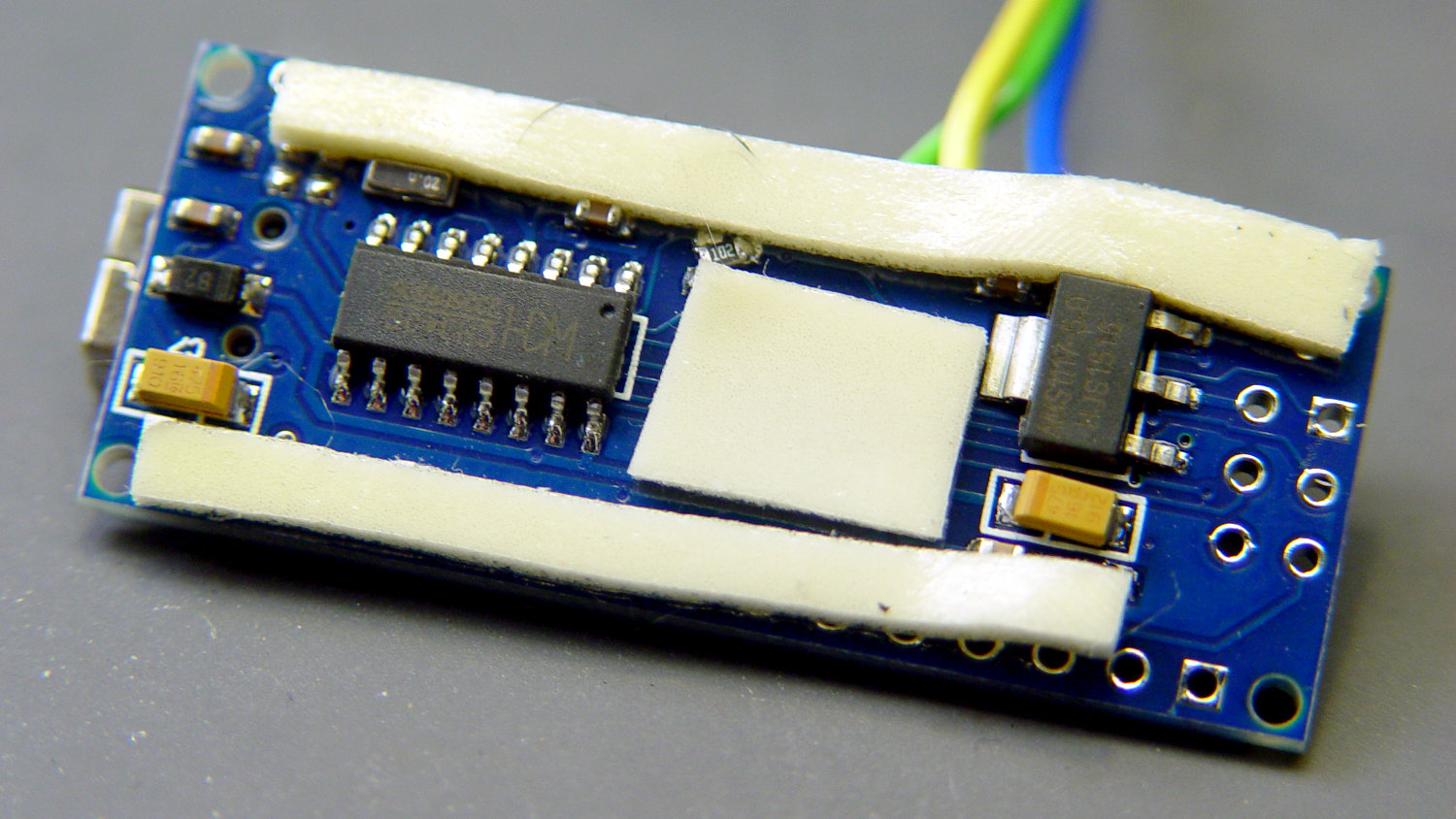
    Two layers of 3M outdoor-rated foam tape clear the bottom-side components and, based on current evidence, its stickiness should stick forever more:

    Triode - Nano PCB - 3M strips
    Triode – Nano PCB – 3M strips

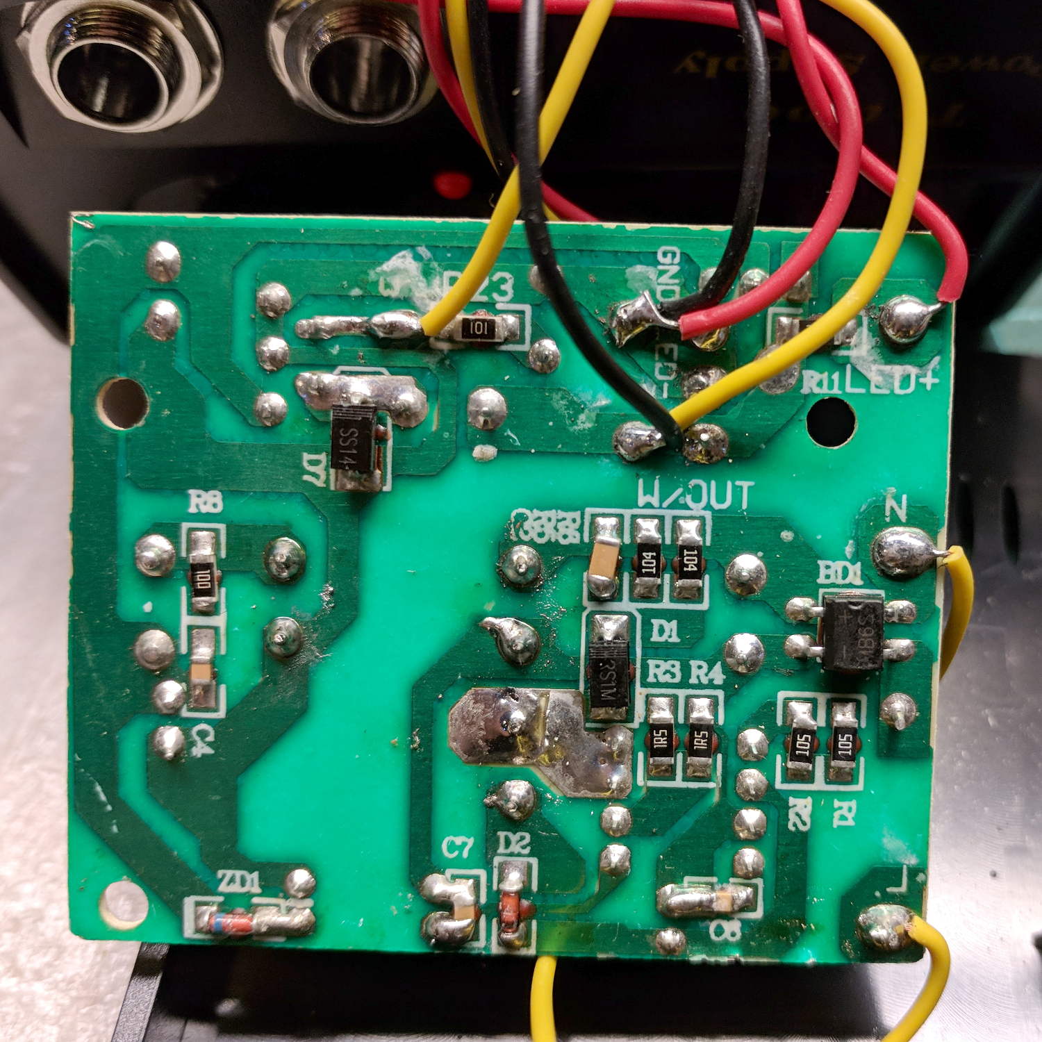
    The alert reader will notice the mis-soldered 1 kΩ SMT resistor above-and-right of the CH340 USB interface chip. I think those two resistors are the isolators between the 328P microcontroller and the CH340, letting you use the TX and RX lines as ordinary I/O without killing either chip.

    Despite the mis-soldering, it evidently passed their QC and works fine. Seeing as how I didn’t notice it until just now, it’ll remain in place until I must open the lamp base for some other reason, which may never happen.

    The data output is now on pin A5, to match the rest of the glowing widgetry:

    Triode - Nano installed
    Triode – Nano installed

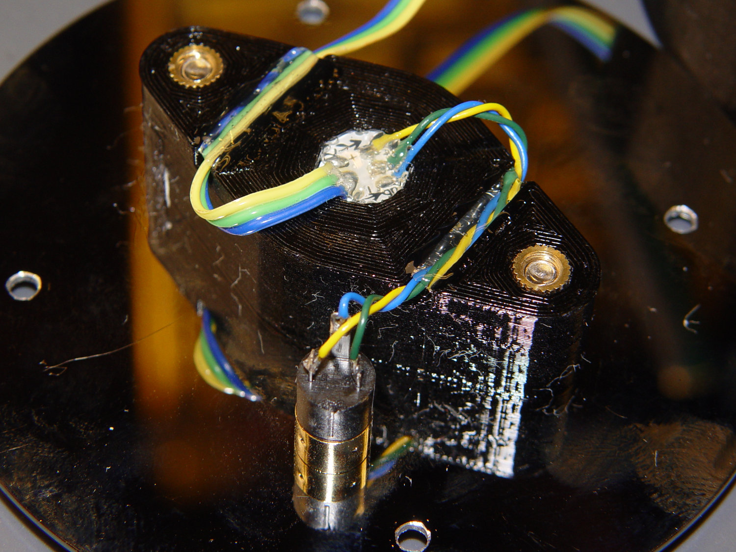
    Blobs of hot melt glue affix the SK6812 and wiring to the socket:

    Triode - socket wiring
    Triode – socket wiring

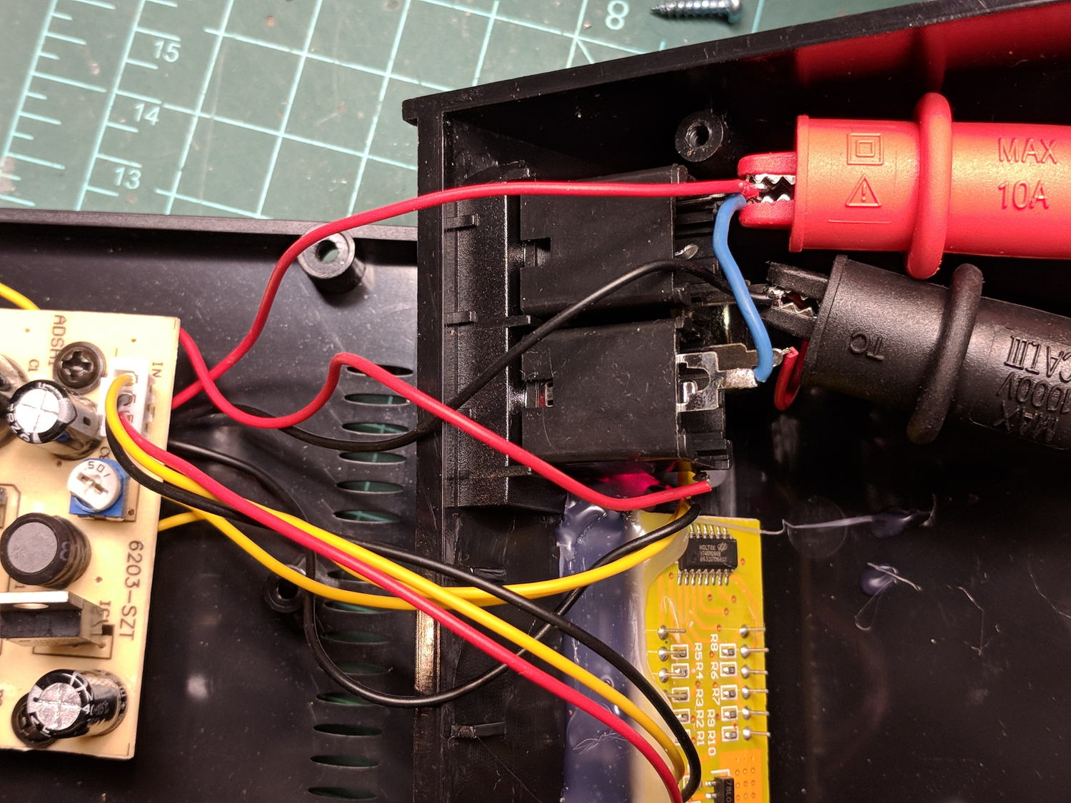
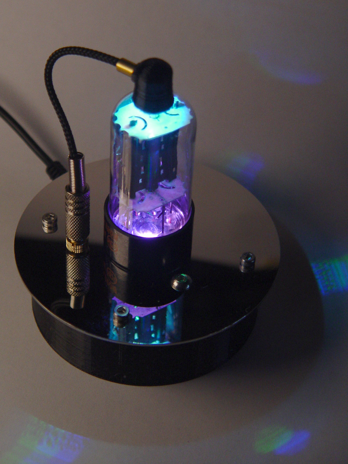
    The original “plate cap” wiring ran directly through a hole in the hard drive platter, which I embiggened for a 3.5 mm panel-mount headphone jack. The knurled metal plug looms next to this smaller tube, but it looks better (in a techie sense) than the raw hole:

    Triode - plate cap plug
    Triode – plate cap plug

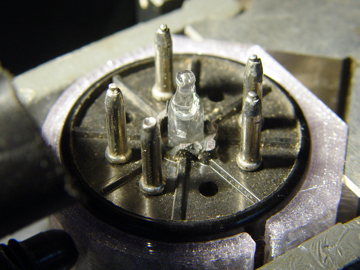
    Octal tubes have an opaque Bakelite base, so I devoted some Quality Shop Time™ to the post:

    Triode - base tip exposed
    Triode – base tip exposed

    Although I’d made a shell drill for 5U4’s base, this base was so crumbly I simply joysticked the spinning cutter around to knock off the rest of the post:

    Triode - finished base
    Triode – finished base

    The shell drill would open the bottom to admit a bit more light. I may do that to see if it makes any visible difference.

    I didn’t expect the serrations in the top mica plate to cast interesting patterns around the platter:

    Triode - cyan-purple phase
    Triode – cyan-purple phase

    Memo to Self: use the shell drill to avoid nicking the evacuation tip!

  • Injured Arm Support Table: Narrow Version

    For reasons not relevant here, I recently conjured a pair of tables to support an injured arm (ours are OK!) in the bathroom: one table fitting in the narrow space adjacent to a toilet and the other across the threshold of a walk-in / sit-down shower.

    The raw material came from a plastic side table intended for outdoor use:

    Arm Supports - OEM Patio table
    Arm Supports – OEM Patio table

    That’s the Patriotic Blue version, which seemed the least offensive of the colors on offer at the local store.

    The plastic pieces unsnap easily enough:

    Arm Supports - top panel disassembly
    Arm Supports – top panel disassembly

    The legs also come apart by pulling outward at the crossover points. You may need to clean the flashing from all the joints, as they’re only as finished as absolutely necessary.

    A table about half the width seemed about right, so I sawed the two top plates off their struts, then angled the strut ends to match the new leg angle:

    Arm Supports - trimming table struts
    Arm Supports – trimming table struts

    Because it’s now completely floppy, I drilled holes for 5 mm screws through the struts:

    Arm Supports - cross-drilling struts
    Arm Supports – cross-drilling struts

    In the process, I discovered stainless steel nyloc nuts tend to gall on stainless steel screws:

    Galled stainless steel cap screw and nyloc nut
    Galled stainless steel cap screw and nyloc nut

    I lost a pair of screws + nuts before I got a clue and began adding a drop of machine oil to each screw before tightening the nuts. Haven’t had that problem with the 3 mm SS screws, so there’s always something new to learn.

    With all the screws in place, the half-table becomes a rigid contraption:

    Arm Supports - narrow table - bottom view
    Arm Supports – narrow table – bottom view

    The top looks like it’s suffering from severe barrel distortion, but it really started out looking that way:

    Arm Supports - narrow table - overview
    Arm Supports – narrow table – overview

    The slat sides are all curved, except the far edge that was once in the middle of the table and now fits against the wall.

    It may be slightly too short, but we can stack foam slabs on the top, probably held in place with cable ties.

    Memo to Self: lube all the stainless steel screws!

  • Just A Typo. It Could Happen To Anyone: Capacitor Edition

    A bag of 100 nF ceramic caps arrived from across the continent (“US Stock”) and failed incoming inspection:

    Mislabeled 100 nF ceramic capacitor - actual 50 nF
    Mislabeled 100 nF ceramic capacitor – actual 50 nF

    The capacitor mark says 104, which is what you’d expect on a 100 nF cap, but the first half-dozen out of the bag measured around 55 nF, far outside even the loosest -20%/+50% tolerance.

    Stipulated: the factory can ship every capacitor it makes with a proper mark.

    Given their (lack of) provenance, they could be mis-marked 47 nF caps.

    Somewhat to my surprise, a refund occurred instantly after I reported the problem.

    Trust, but verify.

  • Tek A6302 Current Probe Derating

    Most currents around here come in tens-of-milliamps, maybe a few hundred, tops, but it’s worth noting some curves from the Tektronix AM503 current amplifier manual for A6302 Hall effect probes:

    Tek A6302 Calibration Setup
    Tek A6302 Calibration Setup

    The maximum current drops from 20 A for frequencies above 20 kHz:

    Tek A6302 Current Probe - Max Current Frequency Derating
    Tek A6302 Current Probe – Max Current Frequency Derating

    There’s a 100 A·μs pulse charge limit:

    Tek A6302 Current Probe - Specified Operating Area
    Tek A6302 Current Probe – Specified Operating Area

    Because the probe is actually a pulse transformer, its internal termination imposes a (small) load on the input circuit:

    Tek A6302 Current Probe - Insertion Impedance
    Tek A6302 Current Probe – Insertion Impedance

    The specs are 100 mΩ at 1 MHz and 500 mΩ at 50 MHz, which means the load is essentially zilch for the circuits and signals I deal with.

    The Tektronix Probes for Current Measurement Systems has some useful descriptions.

    Memo to Self: Should any of those limits matter, rethink what you’re doing.

    An interesting story about the AM503 design from someone who lived through it.

  • Ortlieb Backroller Pack Drop

    Although the pair of Ortlieb Back-Roller packs on Mary’s bike make her look like a long-distance tourist, we’re actually on our way to her garden plot:

    AS30V-0285
    AS30V-0285

    The left-side pack suddenly seemed unusually floppy:

    AS30V-0300
    AS30V-0300

    One second later:

    AS30V-0360
    AS30V-0360

    Another second and it’s visible under my right hand:

    AS30V-0420
    AS30V-0420

    The view from her bike at about the same time:

    Ortlieb-0158
    Ortlieb-0158

    I’m expecting to fall to my right, but it’d have been better if I hadn’t kicked the bag:

    Ortlieb-0169
    Ortlieb-0169

    The pack went under the rear wheel and out the far side:

    Ortlieb-0185
    Ortlieb-0185

    Where it came to rest in the middle of the trail:

    Ortlib pack drop - aftermath
    Ortlib pack drop – aftermath

    Elapsed time from the first picture: just under 5 s.

    Did you notice the other cyclist in the other pictures? She’s why I veered so hard to my right!

    A pair of these latches hold the pack onto the rear rack:

    Ortlieb pack drop - QL latch detail
    Ortlieb pack drop – QL latch detail

    When they’re properly engaged, they look like this:

    Ortlieb pack drop - QL latch - secure
    Ortlieb pack drop – QL latch – secure

    When they’re not, they look like this:

    Ortlieb pack drop - QL latch - whoopsie
    Ortlieb pack drop – QL latch – whoopsie

    Which is obvious in the picture and inconspicuous in real life.

    The strap emerging from the top of the latch serves as both a carrying handle and latch release: pull upward to open the latches and release them from the bar, lift to remove the pack, and carry it away as you go. Installing the pack proceeds in reverse: lower the pack onto the rack bar, release the handle, and the latches engage.

    Unless the pack is empty enough to not quite fully open the latches as you carry it, in which case the closed latches simply rest on the bar. We’ve both made that mistake and I generally give her packs a quick glance to ensure sure they’re latched. In this case, the plastic drawer atop the racks (carrying seedling pots on their way to the garden) completely concealed the pack latches.

    Tree roots have been creasing the asphalt along that section of the rail trail: the bike finally bounced hard enough to lift the drawer and fall off the rack rod.

    Memo to Self: In addition to the visual check, lift the packs using the strap across the middle holding the rolled-down top in place. Remember, don’t check by lifting the carrying handle, because it just releases the latches; another easy mistake to make.

    Whew!

  • Digital Tattoo Power Supply: Polarity Doesn’t Matter

    When I rewired the guts of the digital tattoo power supply to eliminate the series foot switch, I kept the original wiring polarity, with the black wire to the sleeve and the red wire to the tip:

    Tattoo Digital Power Supply - internal view
    Tattoo Digital Power Supply – internal view

    It’s the same color code I (strongly) recommend in the Squidwrench Electronics Workshops: use any color for the ground / common wire as long as it’s black, then, if you have a red wire, use it for the positive supply. You can use yellow for the higher supply voltage, but stop being clever.

    I put suitably colored Powerpoles on the far end of the cable to replace the standard tattoo machine spring clip connector, so I can attach clip leads, battery test fixtures, and so forth and so on.

    We wired the supply into a clip-leaded diode measurement setup with a current limiting resistor and a pair of multimeters to measure the diode current and forward voltage, whereupon we noticed all the meters displayed negative voltages and currents.

    After a frenzy of wire-checking verified their setup was all good, I forced the simplest possible test, herein recreated on my bench:

    Tattoo Digital Power Supply - polarity test
    Tattoo Digital Power Supply – polarity test

    Which produced this display:

    Tattoo Digital Supply - reverse polarity
    Tattoo Digital Supply – reverse polarity

    Huh.

    After a brief exploration of “Trust, but verify” territory, we swapped the clip leads from the power supply and continued the mission.

    Back on my bench, I pulled the supply apart and measured the voltage at the jack terminals:

    Tattoo Digital Power Supply - jack wiring
    Tattoo Digital Power Supply – jack wiring

    Still negative. Huh.

    The bottom of the power supply PCB shows exactly what you should expect by now:

    Tattoo Digital Power Supply - reversed color code
    Tattoo Digital Power Supply – reversed color code

    The red wire near the top of the board is, indeed, soldered to the trace labeled GND and goes to the jack’s tip terminal; the adjacent black wire goes to the front-panel LED. Similarly, the black wire just below it, soldered to the same trace as the yellow wire, goes to the jack’s sleeve terminal; that trace also connects to a resistor leading to the trace labeled LED+ and the LED’s red wire.

    Although tattoo machines run from DC supplies, their motors or vibrators don’t depend on any particular polarity and will run fine with a backwards supply.

    Resoldering the red and black wires where they should go produces the expected sign at the jack:

    Tattoo Digital Supply - meter leads
    Tattoo Digital Supply – meter leads

    Although measuring and plotting diode voltages and currents may seem tedious, actually wiring stuff together and taking data reveals how difficult the real world can be.

    I trusted the supply’s internal color code and, although I’m certain I tested the Powerpoles, I obviously didn’t notice the meter’s sign.

    Memo to self: Sheesh.

  • Tour Easy: Front Derailleur Cable Angle

    Spotted while in the midst of replacing my Tour Easy’s rear grip shifter:

    Tour Easy - front derailleur cable angle
    Tour Easy – front derailleur cable angle

    As you might expect, the cable saws through the side of its ferrule and the brazed-on frame fitting, because it’s been basically impossible (for me, anyhow) to find a replacement derailleur duplicating whatever the good folks at Easy Racers shipped back in 2001.

    On the upside, this derailleur’s cable entry has a nicely rounded ramp eliminating the need for my brass cable pulley widget.

    Memo to Self: Perhaps running the cable around a bearing anchored to the frame fitting would help?

    I’ve obviously forgotten to fix this for several years, so putting it here may serve as a Round Tuit.