The Smell of Molten Projects in the Morning

Ed Nisley's Blog: Shop notes, electronics, firmware, machinery, 3D printing, laser cuttery, and curiosities. Contents: 100% human thinking, 0% AI slop.

Tag: M2

Using and tweaking a Makergear M2 3D printer

  • Eagle HAL Configuration: Sherline HAL File

    More hal-config.lbr tweakage produced enough HAL blocks to completely define the Sherline CNC mill’s HAL connections, all wired up in a multi-page schematic (Eagle-LinuxCNC-Sherline.zip.odt) that completely replaces all the disparate *.hal files I’d been using, plus a new iteration of the hal-write-2.5.ulp Eagle-to-HAL conversion script.

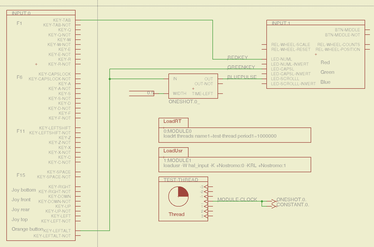
    The first sheet (clicky for more dots) defines the manually configured userspace and realtime modules:

    Sherline Schematic - 1
    Sherline Schematic – 1

    That sheet has three types of Eagle devices:

    • Generalized LoadRT – devices like trivkins that require only a loadrt line
    • Dedicated LoadRT – devices like motion that require functions connected to a realtime thread
    • Generalized LoadUsr – devices like hal_input with a HAL device, but no function pins

    The device’s NAME field contains either the module name (for the specialized devices with functions) or a generic MODULE for everything else, preceded by an optional index that imposes an ordering on the output lines. The device’s VALUE field contains the text that will become the loadrt or loadusr line in the HAL file. Trailing underscores act as separators, but are discarded by the conversion script.

    The immensely long line is the VALUE field that plugs a bunch of variables from the Sherline.ini file into the motion controller.

    The conversion script doesn’t do anything special for those devices, other than transfer the VALUE field to the HAL file. Ordinary HAL devices, the ones with functions that don’t require any special setup, must appear in the conversion script’s list of device names, so that it can recognize them and deal with their connections.

    That sheet produces this part of the HAL file:

    ####################################################
    # Load realtime and userspace modules
    loadrt trivkins
    loadrt [EMCMOT]EMCMOT key=[EMCMOT]SHMEM_KEY num_joints=[TRAJ]AXES base_period_nsec=[EMCMOT]BASE_PERIOD servo_period_nsec=[EMCMOT]SERVO_PERIOD traj_period_nsec=[EMCMOT]SERVO_PERIOD
    loadrt probe_parport
    loadrt hal_parport cfg="[PARPORT]ADDRESS out"
    loadrt stepgen step_type=0,0,0,0
    loadrt pwmgen output_type=0
    loadusr -W hal_manualtoolchange
    loadusr -W hal_input -KA Dual
    loadrt logic count=1 personality=0x104
    

    The conversion script counts the other schematic devices and automagically produces these lines to load their corresponding modules:

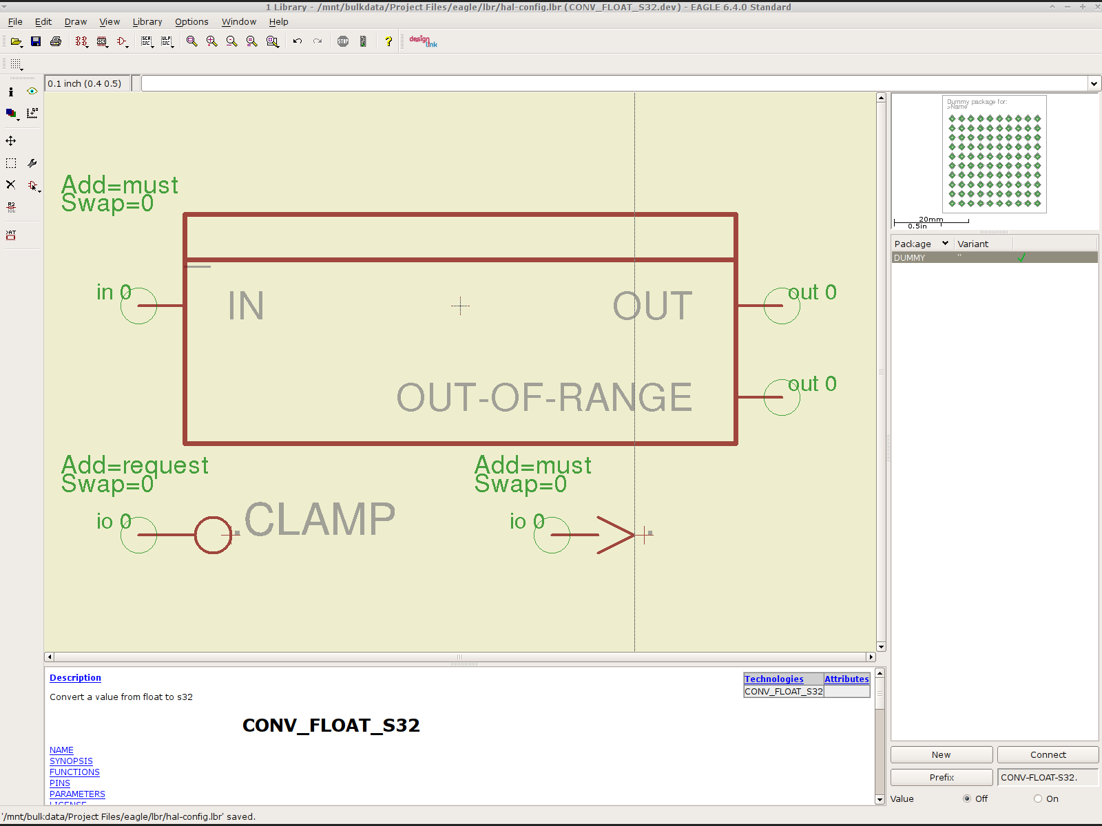
    loadrt constant		count=13
    loadrt and2		count=17
    loadrt conv_float_s32		count=1
    loadrt flipflop		count=4
    loadrt mux2		count=5
    loadrt mux4		count=1
    loadrt not		count=8
    loadrt or2		count=14
    loadrt scale		count=7
    loadrt timedelay		count=1
    loadrt toggle		count=1
    

    Next, the parallel port configuration, which uses the D525’s system board hardware:

    Sherline Schematic - 2
    Sherline Schematic – 2

    The stepconf configuration utility buries the parallel port configuration values in the default HAL file as magic numbers. I moved them to a new stanza in the INI file, although the syntax may not be robust enough to support multiple cards, ports, and configurations. This, however, works for now:

    [PARPORT]
    ADDRESS = 0x378
    RESET_TIME = 10000
    STEPLEN = 25000
    STEPSPACE = 25000
    DIRSETUP = 50000
    DIRHOLD = 50000
    

    That LOGIC block is new and serves as an AND gate that produces a combined enable signal for the parallel port. The stepconf utility uses the X axis enable signal, but, seeing as how the Sherline controller doesn’t use the result, none of that matters on my system.

    The tool height probe and manual tool change wiring:

    Sherline Schematic - 3
    Sherline Schematic – 3

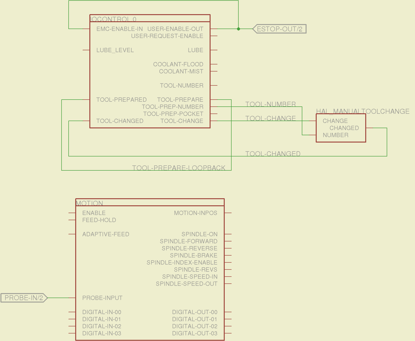
    I’m not convinced the Emergency Stop polarity is correct, but it matches what was in the original HAL file. As before, the Sherline driver box ignores that output, so none of that matters right now.

    Four very similar pages define the XYZA step-and-direction generators. This is the X axis driver:

    Sherline Schematic - 4
    Sherline Schematic – 4

    You can imagine what the next three pages for the YZA logic look like, right? There are also a few blank pages in the schematic, so the numbers jump abruptly.

    The magic part of this is having Eagle manage all the tedious renumbering and counting. If you remember to adjust the name of the first module from, say, AXIS.1 to AXIS.0, then the rest get the proper numbers as you go along.

    The remainder of the schematic implements the Joggy Thing’s logic, much as described there. I discovered, quite the hard way, that copy-and-pasting an entire schematic from elsewhere does horrible things to the device numbering, but I’m not sure how to combine two schematics to limit the damage. In any event, manually adjusting a few pages wasn’t the worst thing I’ve ever had to do; starting with a unified schematic should eliminate that task in the future.

    The miscellaneous buttons:

    Sherline Schematic - 11
    Sherline Schematic – 11

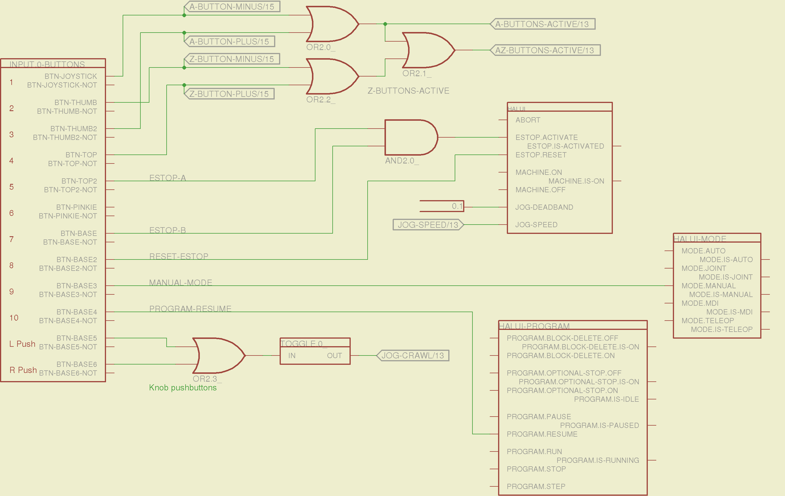
    The joystick and hat values:

    Sherline Schematic - 12
    Sherline Schematic – 12

    The joystick deadband logic now uses the (new with HAL 2.5, I think) input.n.abs-x-flat pins, which eliminated a tangle of window comparator logic.

    The jog speed adjustment logic that sets the fast and crawl speeds:

    Sherline Schematic - 13
    Sherline Schematic – 13

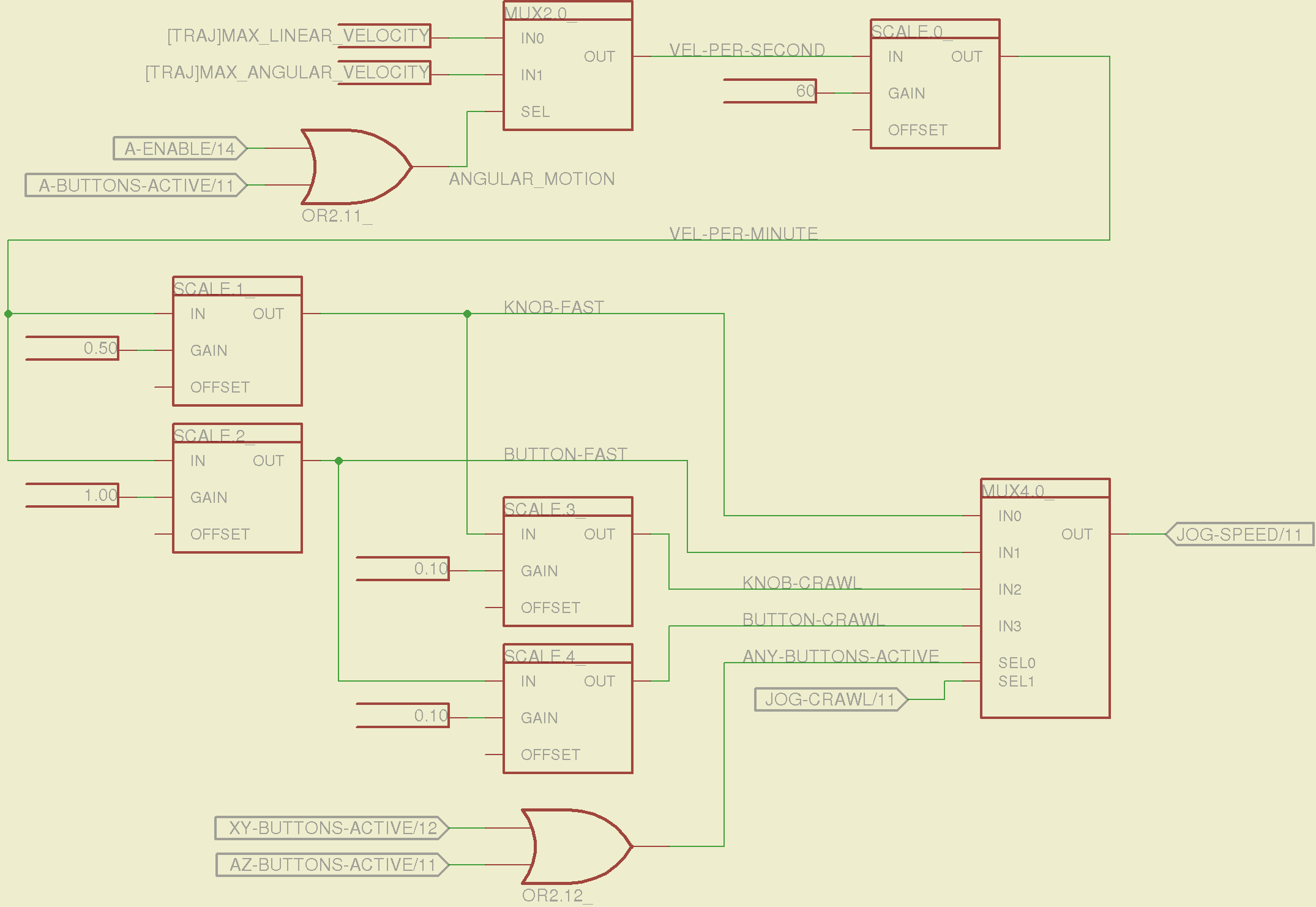
    I should probably put the speed ratios in the INI file, but that’s in the nature of fine tuning.

    The lockout logic that remembers which axis started moving first on a given joystick and locks out the other axis, which greatly simplifies jogging up to an edge without bashing into something else:

    Sherline Schematic - 14
    Sherline Schematic – 14

    Combine all those signals into values that actually tell HAL to jog the axes:

    Sherline Schematic - 15
    Sherline Schematic – 15

    The last page connects all the realtime function pins to the appropriate threads:

    Sherline Schematic - 16
    Sherline Schematic – 16

    The LinuxCNC documentation diverges slightly from the implementation, but a few iterations resolved all the conflicts and had the additional benefit that I had to carefully think through what was actually going on.

    A deep and sincere tip o’ the cycling helmet to the folks making LinuxCNC happen!

    Although the Sherline mill doesn’t have more than a few minutes of power-on time with the new HAL file, the Joggy Thing behaves as it used to and the axes move correctly, so I think the schematic came out pretty close to the original HAL file.

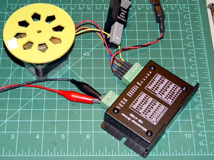
    The next step: draw a new schematic to bring up and exercise a different set of steppers…

  • Eagle HAL Configuration: Nostromo N52 Controller

    Combining some of the pin names generated by hal_input with the recipe for creating HAL devices, here’s a test configuration that hitches an old Nostromo N52 controller to a LinuxCNC system (clicky for more dots):

    Nostromo N52 Controller - HAL config
    Nostromo N52 Controller – HAL config

    The F01 key lights the red LED, the Orange Button lights the green LED, and a oneshot timer pulses the blue LED for half a second after the Button closes. The Thread block defines the connections from the functions to the main timing routine, and the loadrt block defines the thread timing. The hal_input module takes care of its own input sampling in userspace.

    Now, for the classic embedded system “Hello, world!” test:

    Nostromo N52 Controller - F01 test
    Nostromo N52 Controller – F01 test

    It’s amazing how good an LED can make you feel…

    A halscope shot shows the timing relation between the Orange Button (confusingly hitched to the greenkey signal) and the oneshot pulse:

    HalScope - oneshot triggering
    HalScope – oneshot triggering

    That schematic produces this HAL configuration file:

    # HAL config file automatically generated by Eagle-CAD ULP:
    # [/mnt/bulkdata/Project Files/eagle/ulp/hal-write-2.5.ulp]
    # (C) Martin Schoeneck.de 2008
    # Charalampos Alexopoulos 2011
    # Mods Ed Nisley KE4ZNU 2010 2013
    # Path        [/mnt/bulkdata/Project Files/eagle/projects/LinuxCNC HAL Configuration/]
    # ProjectName [Nostromo]
    # File name   [/mnt/bulkdata/Project Files/eagle/projects/LinuxCNC HAL Configuration/Nostromo.hal]
    # Created     [12:28:04 14-Feb-2013]
    
    ####################################################
    # Load realtime and userspace modules
    loadrt threads name1=test-thread period1=1000000
    loadusr -W hal_input -K +Nostromo:0 -KRL +Nostromo:1
    loadrt constant		count=1
    loadrt oneshot		count=1
    
    ####################################################
    # Hook functions into threads
    addf oneshot.0		test-thread
    addf constant.0		test-thread
    
    ####################################################
    # Set parameters
    
    ####################################################
    # Set constants
    setp constant.0.value	0.5
    
    ####################################################
    # Connect Modules with nets
    net bluepulse input.1.led-scrolll oneshot.0.out
    net duration constant.0.out oneshot.0.width
    net greenkey input.0.key-leftalt oneshot.0.in input.1.led-capsl
    net redkey input.0.key-tab input.1.led-numl
    

    A snapshot of the Nostromo.sch, Nostromo.hal, hal_config.lbr, and hal-write-2.5.ulp files is in Nostromo-N52.zip.odt. Rename it to get rid of the ODT suffix, unzip it, and there you go.

  • Gratuitous Engine Jeweling

    While pondering whether I should use the carcass of an old Dell PC to house the stepper drivers and control logic for the LinuxCNC M2 project, I bandsawed a scrap of aluminum sheet to about the right size. It had some truly nasty gouges and bonded-on crud, so I chucked up a wire brush cup in the drill press and had at it:

    Machine jeweled baseplate
    Machine jeweled baseplate

    It’s obvious I haven’t done jeweling in a long time, isn’t it? Even a crude engine jeweling job spiffs things right up, though, even if a cough showcase job like this deserves straighter lines and more precise spacing. The aluminum sheet is far too large for the Sherline, which put CNC right out of consideration, and I’m not up for sufficient crank spinning on the big manual mill.

    I match-marked mounting holes directly from the harvested motherboard and drilled them, whereupon I discovered that the aluminum is a dead-soft gummy alloy that doesn’t machine cleanly: it won’t become the final baseplate.

    Memo to Self: Use the shop vacuum with the nozzle spinward of the brush, fool.

  • Eagle 6.4 Schematics for LinuxCNC 2.5 HAL Configuration: Device Creation Checklist

    I’m updating the Eagle-to-HAL script and library I used to get the Joggy Thing working, with the intent of getting a Nostromo N52 working on another LinuxCNC box.

    To that end, here’s a checklist for creating a new Eagle device corresponding to a HAL module.

    Remember: although this process has a tremendous number of moving parts, you do it exactly once when you need a device that doesn’t already exist. After that, you just click to add an existing device to your schematic, wire it up, then the tedious write-only HAL overhead happens automagically.

    Cross-check the documentation with the actual component code!

    The man page lists the names, pins, parameters, and suchlike, but may have typos. This isn’t a criticism, it’s a fact of life.

    Before investing a ton o’ time creating an Eagle device, load the module and find out what’s really there:

    halrun
    halcmd: loadrt conv_float_s32
    halcmd: show all
    Loaded HAL Components:
    ID      Type  Name                                      PID   State
         4  RT    conv_float_s32                                  ready
         3  User  halcmd2395                                 2395 ready
    
    Component Pins:
    Owner   Type  Dir         Value  Name
         4  float IN              0  conv-float-s32.0.in
         4  s32   OUT             0  conv-float-s32.0.out
         4  bit   OUT         FALSE  conv-float-s32.0.out-of-range
    
    ... snippage ...
    
    Parameters:
    Owner   Type  Dir         Value  Name
         4  bit   RW          FALSE  conv-float-s32.0.clamp
         4  s32   RO              0  conv-float-s32.0.time
         4  s32   RW              0  conv-float-s32.0.tmax
    
    ... snippage ...
    
    Exported Functions:
    Owner   CodeAddr  Arg       FP   Users  Name
     00004  fc0a9000  fc0630b8  YES      0   conv-float-s32.0
    ... snippage ...
    

    Achtung!

    • The module name uses underscores as separators: loadrt conv_float_s32
    • The function name uses h-y-p-h-e-n-s as separators: conv-float-s32.0
    • Unlike in the Linux kernel, the two characters are not equivalent

    Add the HAL Module to the Conversion Script

    The hal-write.ulp script contains a table of all the module names, so you must update the script in parallel with the hal-config.lbr Eagle library.

    However, you can create an Eagle device that is not a HAL module by omitting it from the script. In that case, the Eagle device name will become part of the net names that define and interconnect the pins, but the script will not create a statement to load a module. For example, the hal_input userspace program creates a set of pins for each input device that start with input.n, but there’s no corresponding HAL module. I’ll put up an example of all this in a bit.

    Create a Schematic Symbol

    • The name of the symbol is not critical: CONVERT.sym
      • use either dashes or hyphens as you prefer
    • The >NAME string must be on layer 95-Names
    • No need for a >VALUE string, but put it on layer 96-Values if present
    • HAL pins become symbol pins
      • Use the HAL pin name, with hyphens
      • Set Visibility to Pin
      • Set Direction to in / out / io to match the HAL description
      • Set Function to None to indicate an ordinary net connection
    • Verify the pins against the HAL device!

    Create a HAL Schematic Device

    • The new device name must match the HAL module name, with underscores, as entered in the conversion script table
      • CONV_FLOAT_S32.dev
    • Set the Prefix to the HAL function name, plus a trailing period, with hyphens
      • CONV-FLOAT-S32.
    • Create the Description using copy-and-paste from the HTML source: use the man page in the LinuxCNC doc
      • Ctrl-U in Firefox reveals the HTML source, Ctrl-A and Ctrl-C, flip windows, then Ctrl-V
      • Delete all the boilerplate at the top, leave the centered Title, ditch the reference links
    • Add the symbol you created earlier or reuse an existing symbol
      • Set the symbol NAME to a single underscore: _
      • Change the Add level to must
    • Add a PIN_FUNCTION symbol to the device
      • Change the symbol name from G$1 (or whatever) to a single period: .
      • Change the Add Level to must
    • Add PIN_PARAMETER symbols as needed
      • Change the symbol name from G$1 (or whatever) to the parameter name preceded by a single period: .CLAMP
      • Change the Add Level to request
      • Change the Direction as needed
    • Add the DUMMY physical package, then connect all the pins to pads

    Create a non-HAL Schematic Device

    • The new device name may be anything that’s not in the conversion script table
    • The Prefix must match the desired pin names, plus a trailing period. For hal_input pins:
      • INPUT.
    • Create the Description as above
    • Add the symbol you created earlier
      • Set the symbol NAME to a single underscore: _
      • Change the Add level to must
    • Do not add a PIN_FUNCTION symbol, because it has no corresponding module
    • Add PIN_PARAMETER symbols as needed
      • Change the symbol name from G$1 (or whatever) to the parameter name preceded by a single period: .CLAMP
      • Change the Add Level to request
      • Change the Direction as needed
    • Add the DUMMY physical package, then connect all the pins to pads

    Devices may have multiple Symbols, with different Add Level options; can seems appropriate. As nearly as I can tell, you must name each Symbol as a suffix to the full name to differentiate them within the Device; I use a hyphen before the suffix, so that -KEYS generates INPUT.0-KEYS. Those suffixes don’t appear elsewhere in the generated HAL configuration file.

    Save the library, update it in the schematic editor (Library → Update ...), and you’re set.

    Although it’s tempting, do not include a version number in the library file name, because Eagle stores the file name inside the schematic file along with the devices from that file. As a result, when you bump the library version number and use devices from the new library file, the schematic depends on both library files and there’s no way within Eagle to migrate devices from one library to the other; you must delete the existing devices from the schematic and re-place them from the new library. Or you can do like I did: hand-edit the XML fields inside the library file.

    Eagle HAL Device
    Eagle HAL Device

    You’ll almost certainly drive this procedure off the rails, so let me know what I’ve screwed up. It does, in fact, work wonderfully well and, as far as I’m concerned, makes HAL usable, if only because HAL is a write-only language to start with and now you need not read it to modify it.

  • HB-415M Stepper Driver Heatsinking: Lack Thereof

    Just to see what’s inside, I took those HB-415M drivers apart. They’re not all identical inside:

    HB-415M Driver - interior top
    HB-415M Driver – interior top

    The other side shouldn’t come as much of a surprise:

    HB-415M Driver heatsinking
    HB-415M Driver heatsinking

    Now, admittedly, I’ve applied a heatsink to the top of an epoxy package, but that DIP package has thermal tabs that should connect to the heatsink through a low-thermal-resistance path. A dab (!) of heatsink grease and what might be a thermally conductive plastic sheet atop the package seem, well, insufficient.

    The driver chip sports an Allegro A3992 marking that might be genuine. The datasheet goes into some detail as to how you should lay out the PCB; none of its recommendations made it into the finished product. In particular, the hulking current sense resistors surely have more inductance than you’d like.

    The resistor color code seems odd: black red red silver brown.

    HB-415M current sense resisors
    HB-415M current sense resisors

    Using black as the first band is unexpected, but it’s probably the only way to indicate a low-value resistance without printing the numbers: 0.22 Ω ±1%.

    Ah, well, the peak current isn’t as high as they claim, so it all probably works out in the end.

  • LinuxCNC HAL Pin Names: Belkin Nostromo N52 SpeedPad

    A (formerly Belkin, now Razer, which is evidently unrelated to Mazer Rackham) Nostromo N52 SpeedPad might not be a perfect CNC pendant, but it does have plenty of buttons and an (oddly oriented) XY joypad that might be useful for, say, a 3D printer controller running LinuxCNC.

    Belkin Nostromo N52 SpeedPad
    Belkin Nostromo N52 SpeedPad

    Following the same path as with the Logitech Dual Action Gamepad that became the Joggy Thing, we find that the N52 reports itself as a keyboard and a mouse:

    less /proc/bus/input/devices
    
    ... snippage ...
    I: Bus=0003 Vendor=050d Product=0815 Version=0110
    N: Name="Honey Bee  Nostromo SpeedPad2 "
    P: Phys=usb-0000:00:02.0-10/input0
    S: Sysfs=/devices/pci0000:00/0000:00:02.0/usb2/2-10/2-10:1.0/input/input3
    U: Uniq=
    H: Handlers=kbd event3
    B: EV=100013
    B: KEY=e080ffdf 1cfffff ffffffff fffffffe
    B: MSC=10
    
    I: Bus=0003 Vendor=050d Product=0815 Version=0110
    N: Name="Honey Bee  Nostromo SpeedPad2 "
    P: Phys=usb-0000:00:02.0-10/input1
    S: Sysfs=/devices/pci0000:00/0000:00:02.0/usb2/2-10/2-10:1.1/input/input4
    U: Uniq=
    H: Handlers=mouse1 event4
    B: EV=20017
    B: KEY=70000 0 0 0 0 0 0 0 0
    B: REL=103
    B: MSC=10
    B: LED=7
    

    The corresponding device files belong to the root user:

    ll /dev/input
    ... snippage ...
    crw-r-----  1 root root 13, 67 2013-02-08 11:06 event3
    crw-r-----  1 root root 13, 68 2013-02-08 11:06 event4
    ... snippage ...
    crw-r-----  1 root root 13, 33 2013-02-08 11:06 mouse1
    

    Which calls for some udev trickery to change the owner & permissions during boot / hotplugging so that it becomes available to mere mortals such as I.

    First, get the bus connection information:

    lsusb
    ... snippage ...
    Bus 002 Device 004: ID 050d:0815 Belkin Components Nostromo n52 HID SpeedPad Mouse Wheel
    ... snippage ...
    

    Then dump the attributes:

    udevadm info --query=all --attribute-walk --name=/dev/bus/usb/002/004
    
    Udevadm info starts with the device specified by the devpath and then
    walks up the chain of parent devices. It prints for every device
    found, all possible attributes in the udev rules key format.
    A rule to match, can be composed by the attributes of the device
    and the attributes from one single parent device.
    
      looking at device '/devices/pci0000:00/0000:00:02.0/usb2/2-10':
        KERNEL=="2-10"
        SUBSYSTEM=="usb"
        DRIVER=="usb"
        ATTR{configuration}==""
        ATTR{bNumInterfaces}==" 2"
        ATTR{bConfigurationValue}=="1"
        ATTR{bmAttributes}=="80"
        ATTR{bMaxPower}==" 90mA"
        ATTR{urbnum}=="1354"
        ATTR{idVendor}=="050d"
        ATTR{idProduct}=="0815"
        ATTR{bcdDevice}=="0210"
        ATTR{bDeviceClass}=="00"
        ATTR{bDeviceSubClass}=="00"
        ATTR{bDeviceProtocol}=="00"
        ATTR{bNumConfigurations}=="1"
        ATTR{bMaxPacketSize0}=="8"
        ATTR{speed}=="1.5"
        ATTR{busnum}=="2"
        ATTR{devnum}=="4"
        ATTR{version}==" 1.10"
        ATTR{maxchild}=="0"
        ATTR{quirks}=="0x0"
        ATTR{authorized}=="1"
        ATTR{manufacturer}=="Honey Bee "
        ATTR{product}=="Nostromo SpeedPad2 "
    
    ... snippage ...
    

    Note the trailing blank in the manufacturer and product values.

    Create a new rules file /etc/udev/rule/90-Nostromo.rules to change the group and permissions:

    # Belkin Nostromo N52 SpeedPad controller for LinuxCNC
    # Ed Nisley - KE4ZNU - February 2013
    
    ATTRS{product}=="Nostromo SpeedPad2",GROUP="plugdev",MODE="0660"
    

    Note that the file name must start with a number around 90- to avoid being clobbered by a rule in /lib/udev/rules.d/50-udev-default.rules that (re)sets the permissions to 0640; the doc suggests that rules without numbers happen after all the number rules, so perhaps you could just use meaningful names. That took an embarrassingly long time to figure out…

    There’s no need for the trailing blank in that rule, as the match proceeds left-to-right and stops at the end of the test string.

    You must, perforce, be in the plugdev group. If not, add yourself.

    You need not unplug the N52 to test the rule. Just use:

    sudo udevadm trigger
    

    Which produces the desired result:

    crw-rw----  1 root plugdev 13, 67 2013-02-08 15:09 event3
    crw-rw----  1 root plugdev 13, 68 2013-02-08 15:09 event4
    ... snippage ...
    crw-rw----  1 root plugdev 13, 33 2013-02-08 15:09 mouse1
    

    Poking around using, among other things, xev reveals:

    • Main keypad is the left half of a standard QWERTY keyboard
    • Joypad returns cursor keys, center push = nothing
    • Orange button is, weirdly, the Left-Alt key
    • Wheel is a mouse scroll wheel
    • Push wheel = middle mouse button
    • Thumb pad = space
    • RGB LEDs are, respectively, num-, caps-, and scroll-lock

    Then load HAL:

    halrun
    loadusr -W hal_input -K +Nostromo:0 -KRL +Nostromo:1
    show pin input.*
    loadusr halmeter
    

    The + prefix tells HAL to capture the named device and prevent its events from reaching X. The KRL codes suggest which functions you’re interested in for that particular device. The suffix digit selects successive devices for multiple gadgets matching the same name string.

    Apparently, the N52 reports it can produce all the usual keyboard and mouse values & buttons, even if they’re not connected to physical hardware. I suspect it has generic keyboard / mouse controllers inside, with just a few of the usual matrix crosspoints connected to switches.

    The basic key mapping, sorted by the Nostromo functions:

    Type Dir Name Nostromo key
    bit OUT input.0.key-tab F1
    bit OUT input.0.key-q F2
    bit OUT input.0.key-w F3
    bit OUT input.0.key-e F4
    bit OUT input.0.key-r F5
    bit OUT input.0.key-capslock F6
    bit OUT input.0.key-a F7
    bit OUT input.0.key-s F8
    bit OUT input.0.key-d F9
    bit OUT input.0.key-f F10
    bit OUT input.0.key-leftshift F11
    bit OUT input.0.key-z F12
    bit OUT input.0.key-x F13
    bit OUT input.0.key-c F14
    bit OUT input.0.key-space F15
    bit OUT input.0.key-leftalt Orange button
    bit OUT input.0.key-right Pad bottom
    bit OUT input.0.key-down Pad front
    bit OUT input.0.key-up Pad rear
    bit OUT input.0.key-left Pad top
    bit OUT input.1.btn-middle Wheel press
    s32 OUT input.1.rel-wheel-counts Scroll wheel
    bit IN input.1.led-numl Red LED
    bit IN input.1.led-capsl Green LED
    bit IN input.1.led-scrolll Blue LED

    The bit pins also have inverted values available on the corresponding -not pins. The LEDs have an -invert that flips the sense of the input pin. The rel-wheel pin has other useful tidbits as suffixes; the count changes by ±1 for each wheel detent.

    The Tab key and all the letters auto-repeat, the various Shift and Alt keys do not. That seems to make no difference to the bit values reported by HAL.

    The complete table, sorted by HAL pin name:

    Type Dir Name Nostromo key
    bit OUT input.0.key-0
    bit OUT input.0.key-0-not
    bit OUT input.0.key-1
    bit OUT input.0.key-1-not
    bit OUT input.0.key-102nd
    bit OUT input.0.key-102nd-not
    bit OUT input.0.key-2
    bit OUT input.0.key-2-not
    bit OUT input.0.key-3
    bit OUT input.0.key-3-not
    bit OUT input.0.key-4
    bit OUT input.0.key-4-not
    bit OUT input.0.key-5
    bit OUT input.0.key-5-not
    bit OUT input.0.key-6
    bit OUT input.0.key-6-not
    bit OUT input.0.key-7
    bit OUT input.0.key-7-not
    bit OUT input.0.key-8
    bit OUT input.0.key-8-not
    bit OUT input.0.key-9
    bit OUT input.0.key-9-not
    bit OUT input.0.key-a F7
    bit OUT input.0.key-a-not
    bit OUT input.0.key-apostrophe
    bit OUT input.0.key-apostrophe-not
    bit OUT input.0.key-b
    bit OUT input.0.key-b-not
    bit OUT input.0.key-backslash
    bit OUT input.0.key-backslash-not
    bit OUT input.0.key-backspace
    bit OUT input.0.key-backspace-not
    bit OUT input.0.key-c F14
    bit OUT input.0.key-c-not
    bit OUT input.0.key-capslock F6
    bit OUT input.0.key-capslock-not
    bit OUT input.0.key-comma
    bit OUT input.0.key-comma-not
    bit OUT input.0.key-compose
    bit OUT input.0.key-compose-not
    bit OUT input.0.key-d F9
    bit OUT input.0.key-d-not
    bit OUT input.0.key-delete
    bit OUT input.0.key-delete-not
    bit OUT input.0.key-dot
    bit OUT input.0.key-dot-not
    bit OUT input.0.key-down Pad left
    bit OUT input.0.key-down-not
    bit OUT input.0.key-e F4
    bit OUT input.0.key-e-not
    bit OUT input.0.key-end
    bit OUT input.0.key-end-not
    bit OUT input.0.key-enter
    bit OUT input.0.key-enter-not
    bit OUT input.0.key-equal
    bit OUT input.0.key-equal-not
    bit OUT input.0.key-esc
    bit OUT input.0.key-esc-not
    bit OUT input.0.key-f F10
    bit OUT input.0.key-f-not
    bit OUT input.0.key-f1
    bit OUT input.0.key-f1-not
    bit OUT input.0.key-f10
    bit OUT input.0.key-f10-not
    bit OUT input.0.key-f11
    bit OUT input.0.key-f11-not
    bit OUT input.0.key-f12
    bit OUT input.0.key-f12-not
    bit OUT input.0.key-f2
    bit OUT input.0.key-f2-not
    bit OUT input.0.key-f3
    bit OUT input.0.key-f3-not
    bit OUT input.0.key-f4
    bit OUT input.0.key-f4-not
    bit OUT input.0.key-f5
    bit OUT input.0.key-f5-not
    bit OUT input.0.key-f6
    bit OUT input.0.key-f6-not
    bit OUT input.0.key-f7
    bit OUT input.0.key-f7-not
    bit OUT input.0.key-f8
    bit OUT input.0.key-f8-not
    bit OUT input.0.key-f9
    bit OUT input.0.key-f9-not
    bit OUT input.0.key-g
    bit OUT input.0.key-g-not
    bit OUT input.0.key-grave
    bit OUT input.0.key-grave-not
    bit OUT input.0.key-h
    bit OUT input.0.key-h-not
    bit OUT input.0.key-home
    bit OUT input.0.key-home-not
    bit OUT input.0.key-i
    bit OUT input.0.key-i-not
    bit OUT input.0.key-insert
    bit OUT input.0.key-insert-not
    bit OUT input.0.key-j
    bit OUT input.0.key-j-not
    bit OUT input.0.key-k
    bit OUT input.0.key-k-not
    bit OUT input.0.key-kp0
    bit OUT input.0.key-kp0-not
    bit OUT input.0.key-kp1
    bit OUT input.0.key-kp1-not
    bit OUT input.0.key-kp2
    bit OUT input.0.key-kp2-not
    bit OUT input.0.key-kp3
    bit OUT input.0.key-kp3-not
    bit OUT input.0.key-kp4
    bit OUT input.0.key-kp4-not
    bit OUT input.0.key-kp5
    bit OUT input.0.key-kp5-not
    bit OUT input.0.key-kp6
    bit OUT input.0.key-kp6-not
    bit OUT input.0.key-kp7
    bit OUT input.0.key-kp7-not
    bit OUT input.0.key-kp8
    bit OUT input.0.key-kp8-not
    bit OUT input.0.key-kp9
    bit OUT input.0.key-kp9-not
    bit OUT input.0.key-kpasterisk
    bit OUT input.0.key-kpasterisk-not
    bit OUT input.0.key-kpdot
    bit OUT input.0.key-kpdot-not
    bit OUT input.0.key-kpenter
    bit OUT input.0.key-kpenter-not
    bit OUT input.0.key-kpminus
    bit OUT input.0.key-kpminus-not
    bit OUT input.0.key-kpplus
    bit OUT input.0.key-kpplus-not
    bit OUT input.0.key-kpslash
    bit OUT input.0.key-kpslash-not
    bit OUT input.0.key-l
    bit OUT input.0.key-l-not
    bit OUT input.0.key-left Pad top
    bit OUT input.0.key-left-not
    bit OUT input.0.key-leftalt Orange button
    bit OUT input.0.key-leftalt-not
    bit OUT input.0.key-leftbrace
    bit OUT input.0.key-leftbrace-not
    bit OUT input.0.key-leftctrl
    bit OUT input.0.key-leftctrl-not
    bit OUT input.0.key-leftmeta
    bit OUT input.0.key-leftmeta-not
    bit OUT input.0.key-leftshift F11
    bit OUT input.0.key-leftshift-not
    bit OUT input.0.key-m
    bit OUT input.0.key-m-not
    bit OUT input.0.key-minus
    bit OUT input.0.key-minus-not
    bit OUT input.0.key-n
    bit OUT input.0.key-n-not
    bit OUT input.0.key-numlock
    bit OUT input.0.key-numlock-not
    bit OUT input.0.key-o
    bit OUT input.0.key-o-not
    bit OUT input.0.key-p
    bit OUT input.0.key-p-not
    bit OUT input.0.key-pagedown
    bit OUT input.0.key-pagedown-not
    bit OUT input.0.key-pageup
    bit OUT input.0.key-pageup-not
    bit OUT input.0.key-pause
    bit OUT input.0.key-pause-not
    bit OUT input.0.key-q F2
    bit OUT input.0.key-q-not
    bit OUT input.0.key-r F5
    bit OUT input.0.key-r-not
    bit OUT input.0.key-right Pad bottom
    bit OUT input.0.key-right-not
    bit OUT input.0.key-rightalt
    bit OUT input.0.key-rightalt-not
    bit OUT input.0.key-rightbrace
    bit OUT input.0.key-rightbrace-not
    bit OUT input.0.key-rightctrl
    bit OUT input.0.key-rightctrl-not
    bit OUT input.0.key-rightmeta
    bit OUT input.0.key-rightmeta-not
    bit OUT input.0.key-rightshift
    bit OUT input.0.key-rightshift-not
    bit OUT input.0.key-s F8
    bit OUT input.0.key-s-not
    bit OUT input.0.key-scrolllock
    bit OUT input.0.key-scrolllock-not
    bit OUT input.0.key-semicolon
    bit OUT input.0.key-semicolon-not
    bit OUT input.0.key-slash
    bit OUT input.0.key-slash-not
    bit OUT input.0.key-space F15
    bit OUT input.0.key-space-not
    bit OUT input.0.key-sysrq
    bit OUT input.0.key-sysrq-not
    bit OUT input.0.key-t
    bit OUT input.0.key-t-not
    bit OUT input.0.key-tab F1
    bit OUT input.0.key-tab-not
    bit OUT input.0.key-u
    bit OUT input.0.key-u-not
    bit OUT input.0.key-up Pad right
    bit OUT input.0.key-up-not
    bit OUT input.0.key-v
    bit OUT input.0.key-v-not
    bit OUT input.0.key-w F3
    bit OUT input.0.key-w-not
    bit OUT input.0.key-x F13
    bit OUT input.0.key-x-not
    bit OUT input.0.key-y
    bit OUT input.0.key-y-not
    bit OUT input.0.key-z F12
    bit OUT input.0.key-z-not
    bit OUT input.1.btn-middle Wheel press
    bit OUT input.1.btn-middle-not  … inverted
    bit OUT input.1.btn-mouse
    bit OUT input.1.btn-mouse-not
    bit OUT input.1.btn-right
    bit OUT input.1.btn-right-not
    bit IN input.1.led-capsl Green LED
    bit IN input.1.led-capsl-invert
    bit IN input.1.led-numl Red LED
    bit IN input.1.led-numl-invert
    bit IN input.1.led-scrolll Blue LED
    bit IN input.1.led-scrolll-invert
    s32 OUT input.1.rel-wheel-counts Scroll wheel
    float OUT input.1.rel-wheel-position  =count/scale
    bit IN input.1.rel-wheel-reset Clear pos’n
    float IN input.1.rel-wheel-scale  count→pos’n
    s32 OUT input.1.rel-x-counts
    float OUT input.1.rel-x-position
    bit IN input.1.rel-x-reset
    float IN input.1.rel-x-scale
    s32 OUT input.1.rel-y-counts
    float OUT input.1.rel-y-position
    bit IN input.1.rel-y-reset
    float IN input.1.rel-y-scale
  • HB-415M Stepper Driver Measurements

    As mentioned there, the usual eBay vendor shipped HB-415M drivers instead of the advertised 2M415 drivers. Based on the Chinese datasheet and some poking around, I got a test setup working with a bench supply, a signal generator, and a NEMA 17 stepper motor with 2 Ω windings.

    HB-415M Driver - test setup
    HB-415M Driver – test setup

    Yes, it’s that stepper motor and interrupter wheel.

    First observation: the ENA input is active high. Pulling it low to turn on the optocoupler disables the drive output, which is exactly the opposite of what’s shown in the datasheet, which means that the driver will run quite happily with nothing connected to the ENA pin. The optoisolator current runs about 11 mA from a 5 V supply, close enough to the 10 mA typical spec, but the signal generator thinks it’s providing a TTL pulse output.

    Second observation: the driver’s actual winding current doesn’t match the DIP switch setting.

    Here’s the 1/8 microstep winding current for the 1.50 A peak setting, with a 0.5 A/div vertical calibration:

    HB-415M 8-step 1.5A 20V
    HB-415M 8-step 1.5A 20V

    Sure looks like 1 A peak, doesn’t it?

    The ratio seems close to 0.707 and remains consistent across all current settings, so I’d lay long money that the designer confused “peak” and “RMS” values, then figured the current sense resistor or chose the internal coefficients to produce the corresponding RMS current for the peak value.

    The reduced current produces not very much torque at all; negotiations are in progress for a partial refund based on eBay’s “item not as described” process…