-
CO₂ Laser Tube Current: RMS Pulse Measurement
Laser power settings of 10, 20, and 30% obviously produce different results:

Pulse Timing Pattern – cardboard – 10 20 30 pct However, the scope traces for PWM values under about 25% all look pretty much like this:

Tube Current – 10pct – 250mm-s – 5ma-div Rather than a simple constant current source, the power supply produces very high amplitude current pulses for low PWM inputs, with no visible differences between any of the PWM values.
The scope can compute the RMS value of (a section of) the trace, so I aimed it at traces captured from the upper left block of this test pattern:

Pulse Timing Pattern – 1 mm blocks Because the pulses have such a high amplitude, I set the Tek AM502 current amp at 100 mA/div to capture the entire pulse. Measuring a part of the trace without a signal gives the baseline noise level:
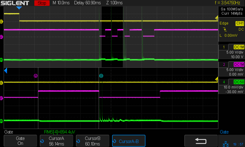
Tube Current – gray bars – 40pct – RMS baseline – 100 ma-div The scope display is 10 mV/div, so 1 mVRMS (close enough to the 894.4 µV reported just above the bottom label row) means 10 mARMS of noise. Given that 100% PWM corresponds to about 25 mA (DC-ish during the pulse), the RMS numbers may not have any significant figures.
A slide show of the results so you can page through them:
The RMS value comes from the trace between the A and B cursors.
Extracting the numbers:
- 0% PWM → 1 mV → 10 mARMS
- 10% → 2.3 mV → 23 mA
- 20% → 2.0 mV → 20 mA
- 30% → 3.0 mV → 30 mA
- 40% → 2.3 mV → 23 mA
Which says I’m measuring either too much of the wrong thing or not enough of the right thing: there may be no baby in this particular bathwater.


-
Subscribe
Subscribed
Already have a WordPress.com account? Log in now.
