-
CO₂ Laser Cutter: Random Dots On Engravings
The LightBurn forums have many despairing posts from folks with CO₂ lasers sprinkling random dots all over their engravings:
- Weird dots all over my engraving
- Dots appear all around engraving
- Random dots when engraving
- Just search for engraving dots to find many more
Well, as it turns out, engraving lots of small test patterns on scrap acrylic and peering at the results revealed the same problem:

Engraving Target – stray laser pulse – sizes The test patterns were engraved at various power levels, which was the whole point of the exercise: I was looking at the current waveforms, rather than the acrylic. Despite that, the result should be solid blocks with no speckles in between, which is not quite what happened.
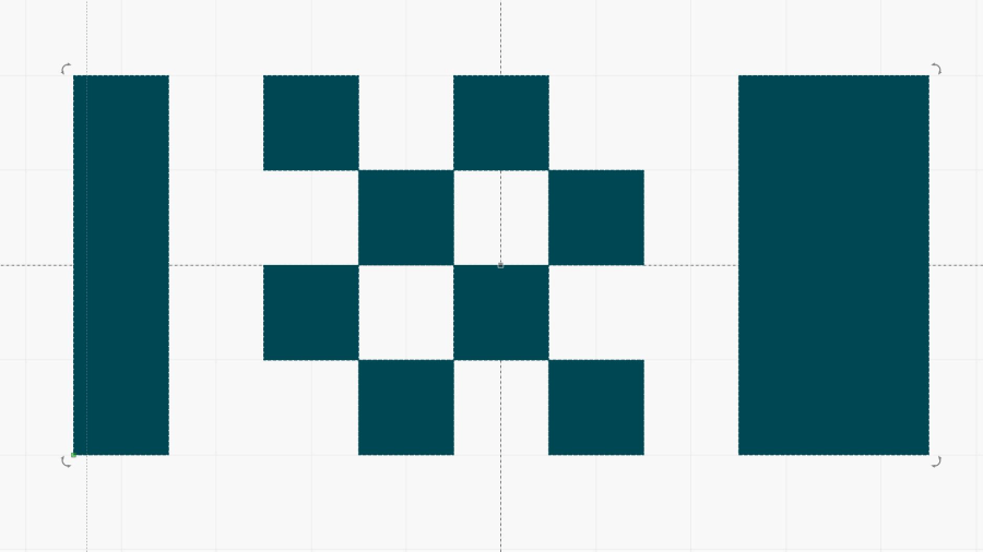
For reference, the test pattern:
Pulse Timing Pattern – 1 mm blocks An early hint came from a trace captured while looking at an entire scan line across the pattern:

Tube Current – gray bars – 20pct – RMS pulse – 100 ma-div See that isolated spike left of center, where the
L-ONsignal (magenta trace) is high? That shouldn’t be possible.Setting the scope to trigger when the L-ON signal is high (= laser power supply disabled) and the tube current is more than a few milliamps (= laser beam active) captures those errant dots.
Sometimes a spurious pulse happens just after
L-ONgoes high to disable the HV output:
Tube Current – 20pct – glitch risng edge 30mA trig – 10 ma-div The X axis stepper DIR signal (yellow trace) shows the laser was scanning right-to-left, so the glitch will be just to the left of the 2 mm block in the pattern. In point of fact, it’s about ¾ of the way down the right-hand column:

Engraving Target – stray laser pulses A closer look shows a distinct circular pit at the end of the line:

Engraving Target – stray laser pulse – detail The two left-to-right lines bracketing that line also show how the high-intensity pulses affect the laser beam startup intensity during a scan line.
Sometimes the glitches happen quite some time after the laser turns off:

Tube Current – 20pct – glitch 30mA trig – 10 ma-div Sometimes they’re in the middle of what should be a blank space:

Tube Current – 20pct – glitch pulse offscale – 10 ma-div The glitches are not always full-scale events. The two nearly invisible pulses just to the right of the block (bottom green trace) make the smaller dots you can see on the targets:

Tube Current – 20pct – glitch pulses – 10 ma-div As far as I can tell, spurious dots happen most often with current levels around 20% PWM, less at 10% PWM, and rarely above 30% PWM. I think it has something to do with the chaotic spikes that the power supply produces at lower currents, instead of the relatively stable outputs for higher currents.
Although these measurements are for the replacement HV supply I got when the original supply failed, I saw similar chaotic waveforms with a Cloudray HV supply I bought as a backup. Given that other people have reported similar random dots with many other machines & power supplies, I think these scope traces show where the dots come from: all the power supplies behave the same way.
The only way to reduce the number of speckles is to use higher power, which will require higher scanning speeds to achieve similar results. Unfortunately, higher speeds give the power supply less settling time, so there may be no good answer.
I haven’t been able to find any “official” schematics for the HV laser power supplies shipped in typical lasers (there are many terminal wiring diagrams), so I have no idea how the
L-ONsignal controls the output current. Apparently the oscillating chaos inside the power supply occasionally punches through the output switch, which isn’t too surprising given the voltage and power levels in there.If nothing else, the acrylic test pieces look pretty on the microscope positioner:

Edge-lit engraving test target In the usual techie sort of way …
-
Subscribe
Subscribed
Already have a WordPress.com account? Log in now.
