-
Chocolate Molds: Software Stack
This derives directly from the cookie cutter / press stack, so check that series for more background and explanation. Some height map thoughts and preliminary doodling led up to this.
We start with a tiny grayscale image file that defines the height of each point in the mold:
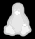
Tux Feed that file into a Bash script:
./MakeMold.sh Tux.pngAnd a corresponding STL file pops out:
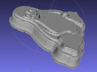
Tux positive mold – solid model – oblique The
MakeMoldBash script orchestrates the whole thing:#!/bin/bash DotsPerMM=3.0 MapHeight=5 ImageName="${1%%.*}" rm ${ImageName}_* ${ImageName}-positive.stl echo Normalize and prepare grayscale image... convert $1 -type Grayscale -depth 8 -trim +repage -flip +set comment ${ImageName}_prep.png echo Create PGM files... convert ${ImageName}_prep.png -compress none ${ImageName}_map.pgm convert ${ImageName}_prep.png -white-threshold 1 -compress none ${ImageName}_plate.pgm echo Create height map data files... ImageX=`identify -format '%[fx:w]' ${ImageName}_map.pgm` ImageY=`identify -format '%[fx:h]' ${ImageName}_map.pgm` echo Width: ${ImageX} x Height: ${ImageY} cat ${ImageName}_map.pgm | tr -s ' \012' '\012' | tail -n +5 | column -x -c $((8*$ImageX)) > ${ImageName}_map.dat cat ${ImageName}_plate.pgm | tr -s ' \012' '\012' | tail -n +5 | column -x -c $((8*$ImageX)) > ${ImageName}_plate.dat echo Create mold positive... time openscad -D fnPlate=\"${ImageName}_plate.dat\" \ -D fnMap=\"${ImageName}_map.dat\" -D Height=$MapHeight \ -D ImageX=$ImageX -D ImageY=$ImageY -D DotsPerMM=$DotsPerMM \ -o ${ImageName}-positive.stl MoldPositive.scadThe first
convertnormalizes the grayscale file and produces a PNG file in a standard format.The next two
convertoperations translate that PNG file into uncompressed PGM files with the data as ASCII text required by OpenSCAD’ssurface()function. It’s not in the proper format, however, so a few lines of Bash-fu rearrange the data into DAT files; the extension is arbitrary.Then OpenSCAD eats those files along with a bunch of configuration settings and spits out a solid model of the positive mold in STL format.
The
MakePositive.scadOpenSCAD source code:// Mold positive pattern from grayscale height map using Minkowski sum // Ed Nisley KE4ZNU - February 2014 - adapted from cookie press, added alignment pins //----------------- // Mold files fnMap = "SqWr_map.dat"; // override with -D 'fnMap="whatever.dat"' fnPlate = "SqWr_plate.dat"; // override with -D 'fnPlate="whatever.dat"' DotsPerMM = 3.0; // overrride with -D DotsPerMM=number MapHeight = 5.0; // overrride with -D MapHeight=number ImageX = 100; // overrride with -D ImageX=whatever ImageY = 100; MapScaleXYZ = [1/DotsPerMM,1/DotsPerMM,MapHeight/255]; PlateScaleXYZ = [1/DotsPerMM,1/DotsPerMM,1.0]; echo("Press File: ",fnMap); echo("Plate File: ",fnPlate); echo(str("ImageX:",ImageX," ImageY: ", ImageY)); echo(str("Map Height: ",MapHeight)); echo(str("Dots/mm: ",DotsPerMM)); echo(str("Scale Map: ",MapScaleXYZ," Plate: ",PlateScaleXYZ)); //- Extrusion parameters - must match reality! ThreadThick = 0.25; ThreadWidth = 2.0 * ThreadThick; //- Buid parameters PlateThick = IntegerMultiple(1.0,ThreadThick); // solid plate under press relief PinOD = 1.75; // locating pin diameter PinDepth = PlateThick; // ... depth into bottom surface = total length/2 PinOC = 20.0; // spacing within mold item echo(str("Pin depth: ",PinDepth," spacing: ",PinOC)); //- Useful info function IntegerMultiple(Size,Unit) = Unit * ceil(Size / Unit); HoleWindage = 0.2; Protrusion = 0.1; // make holes & unions work correctly MaxConvexity = 5; // used for F5 previews in OpenSCAD GUI ZFuzz = 0.2; // numeric chaff just above height map Z=0 plane //----------------- // Import plate height map, slice off a slab to define outline module Slab(Thick=1.0) { intersection() { translate([0,0,Thick/2]) cube([2*ImageX,2*ImageY,Thick],center=true); scale(PlateScaleXYZ) difference() { translate([0,0,-ZFuzz]) surface(fnPlate,center=true,convexity=MaxConvexity); translate([0,0,-1]) cube([2*ImageX,2*ImageY,2],center=true); } } } //- Put peg grid on build surface module ShowPegGrid(Space = 10.0,Size = 1.0) { Range = floor(50 / Space); for (x=[-Range:Range]) for (y=[-Range:Range]) translate([x*Space,y*Space,Size/2]) %cube(Size,center=true); } //-- convert cylinder to low-count polygon module PolyCyl(Dia,Height,ForceSides=0) { // based on nophead's polyholes Sides = (ForceSides != 0) ? ForceSides : (ceil(Dia) + 2); FixDia = Dia / cos(180/Sides); cylinder(r=(FixDia + HoleWindage)/2, h=Height, $fn=Sides); } //-- Locating pin hole with glue recess // Default length is two pin diameters on each side of the split module LocatingPin(Dia=PinOD,Len=0.0) { PinLen = (Len != 0.0) ? Len : (4*Dia); translate([0,0,-ThreadThick]) PolyCyl((Dia + 2*ThreadWidth),2*ThreadThick,4); translate([0,0,-2*ThreadThick]) PolyCyl((Dia + 1*ThreadWidth),4*ThreadThick,4); translate([0,0,-(Len/2 + ThreadThick)]) PolyCyl(Dia,(Len + 2*ThreadThick),4); } //- Build it //ShowPegGrid(); echo("Building mold"); union() { difference() { Slab(PlateThick + Protrusion); for (i=[-1,1]) translate([0,i*PinOC/2,0]) rotate(180/4) LocatingPin(Len=2*PinDepth); } translate([0,0,PlateThick]) // cookie press height map scale(MapScaleXYZ) difference() { translate([0,0,-ZFuzz]) surface(fnMap,center=true,convexity=MaxConvexity); translate([0,0,-1]) cube([2*ImageX,2*ImageY,2],center=true); } }The molds have alignment pin holes in the back:
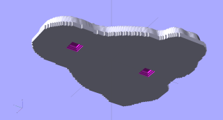
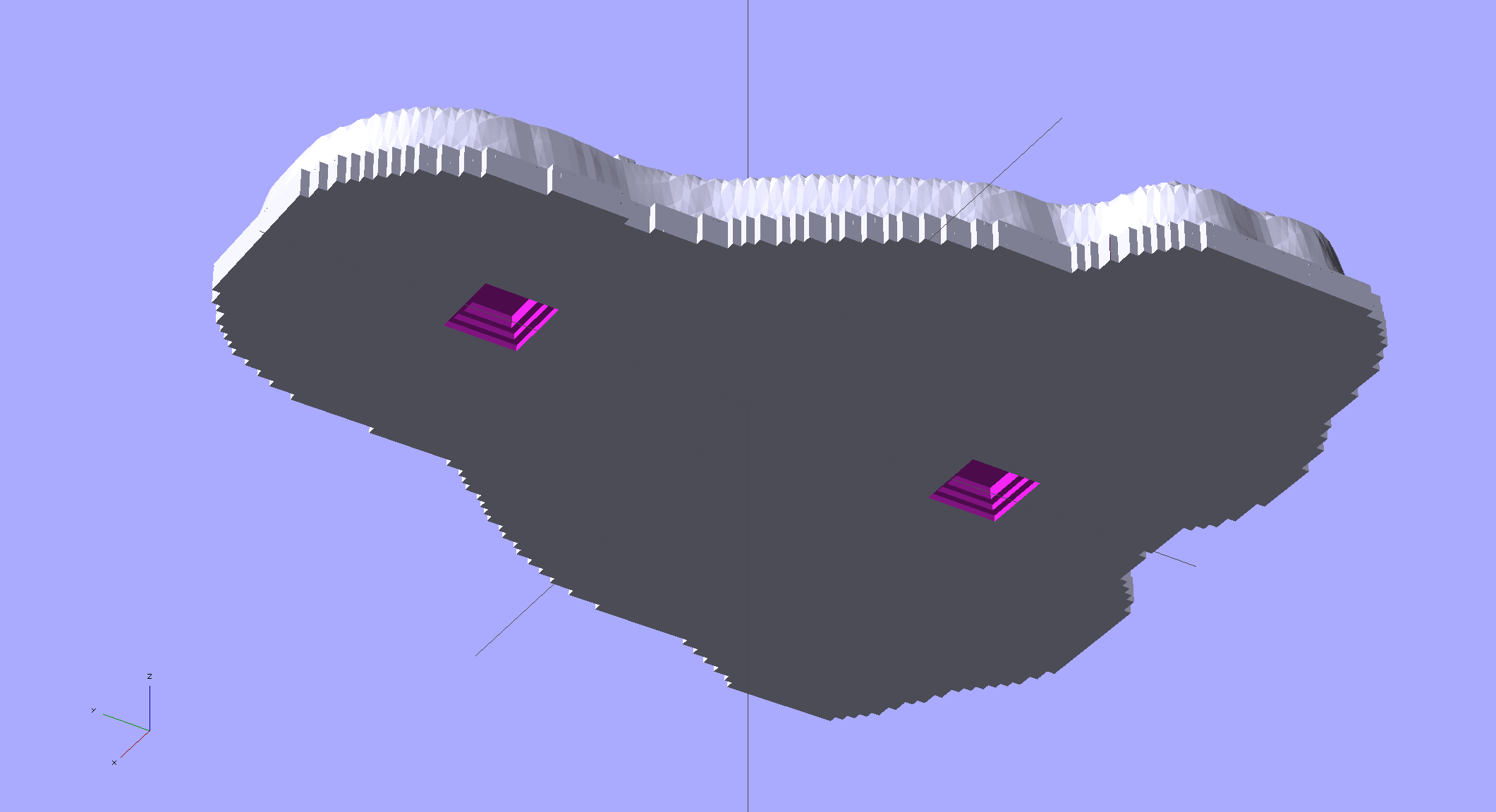
Tux positive mold – solid model – backside That match up with the holes in a baseplate:
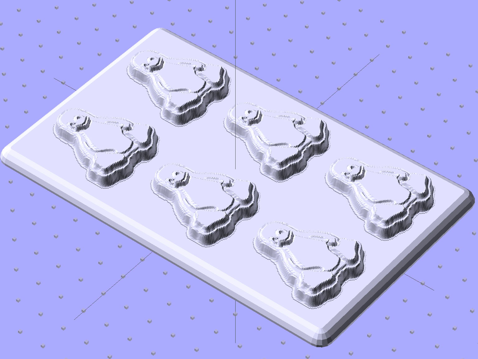
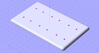 The plate holds the molds in place, perhaps with tapeless sticky, while you’re slathering silicone goop to make the negative mold: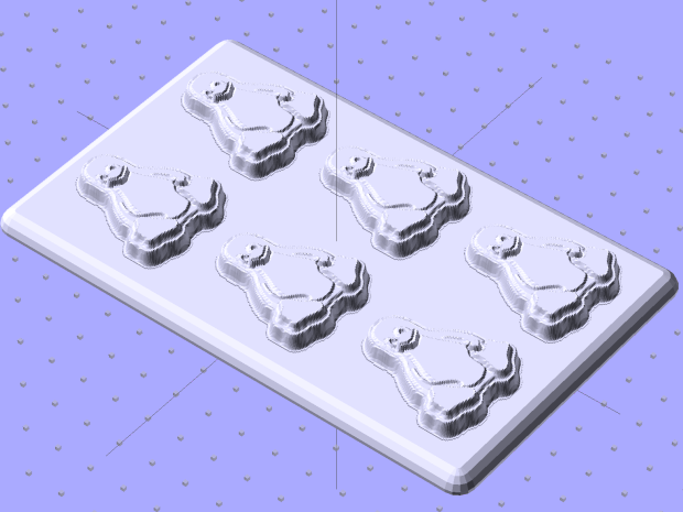
Tux Positive Mold Framework – 2×3 array As you might expect, the OpenSCAD file that generates the plate-with-holes can also embed the positive molds atop the plate, so you could get a solid (well, infilled at 20%) chunk of plastic without attaching the molds. I’d rather do the plate separately from the molds, so you can recycle the plate for many different molds. Your mileage may vary.
The
Positive Mold Framework.scadOpenSCAD source code:// Positive mold framework for chocolate slabs // Ed Nisley - KE4ZNU - January 2014 Layout = "FramePins"; // FramePins FrameMolds Pin //- Extrusion parameters must match reality! // Print with 2 shells and 3 solid layers ThreadThick = 0.20; ThreadWidth = 0.40; Protrusion = 0.1; // make holes end cleanly HoleWindage = 0.2; //---------------------- // Dimensions FileName = "Tux-positive.stl"; // overrride with -D Molds = [2,3]; // count of molds within framework MoldOC = [40.0,45.0]; // on-center spacing of molds MoldSlab = 1.0; // thickness of slab under molds BaseThick = 5.0; BaseSize = [(Molds[0]*MoldOC[0] + 0),(Molds[1]*MoldOC[1] + 0),BaseThick]; echo(str("Overall base: ",BaseSize)); PinOD = 1.75; // locating pin diameter PinLength = 2.0; // ... total length PinOC = 20.0; // spacing within mold item //---------------------- // Useful routines //- Put peg grid on build surface module ShowPegGrid(Space = 10.0,Size = 1.0) { RangeX = floor(100 / Space); RangeY = floor(125 / Space); for (x=[-RangeX:RangeX]) for (y=[-RangeY:RangeY]) translate([x*Space,y*Space,Size/2]) %cube(Size,center=true); } module PolyCyl(Dia,Height,ForceSides=0) { // based on nophead's polyholes Sides = (ForceSides != 0) ? ForceSides : (ceil(Dia) + 2); FixDia = Dia / cos(180/Sides); cylinder(r=(FixDia + HoleWindage)/2, h=Height, $fn=Sides); } // Locating pin hole with glue recess // Default length is two pin diameters on each side of the split module LocatingPin(Dia=PinOD,Len=0.0) { PinLen = (Len != 0.0) ? Len : (4*Dia); translate([0,0,-ThreadThick]) PolyCyl((Dia + 2*ThreadWidth),2*ThreadThick,4); translate([0,0,-2*ThreadThick]) PolyCyl((Dia + 1*ThreadWidth),4*ThreadThick,4); translate([0,0,-(Len/2 + ThreadThick)]) PolyCyl(Dia,(Len + 2*ThreadThick),4); } module LocatingPins(Length) { for (i=[-1,1]) translate([0,i*PinOC/2,0]) rotate(180/4) LocatingPin(Len=Length); } //-- import a single mold item module MoldItem() { import(FileName,convexity=10); } //-- Overall frame shape module Frame() { // translate([0,0,BaseSize[2]/2]) // platform under molds // cube(BaseSize,center=true); difference() { hull() for (i=[-1,1], j=[-1,1]) translate([i*BaseSize[0]/2,j*BaseSize[1]/2,0]) sphere(r=BaseThick); translate([0,0,-BaseThick]) cube(2*BaseSize,center=true); } } //- Build it ShowPegGrid(); if (Layout == "Pin") LocatingPin(Len=PinLength); if (Layout == "Frame") Frame(); if (Layout == "FramePins") difference() { Frame(); translate([-MoldOC[0]*(Molds[0] - 1)/2,-MoldOC[1]*(Molds[1] - 1)/2,0]) for (i=[0:Molds[0]-1],j=[0:Molds[1]-1]) translate([i*MoldOC[0],j*MoldOC[1],BaseSize[2]]) LocatingPins(BaseThick); } if (Layout == "FrameMolds") { Frame(); translate([-MoldOC[0]*(Molds[0] - 1)/2,-MoldOC[1]*(Molds[1] - 1)/2,0]) for (i=[0:Molds[0]-1],j=[0:Molds[1]-1]) translate([i*MoldOC[0],j*MoldOC[1],BaseThick - MoldSlab + Protrusion]) MoldItem(); }And then it’s time to pour some chocolate… which someone else knows how to do much better than I!


-
Subscribe
Subscribed
Have a WordPress.com account? Log in now.

