-
Hall Effect LED Current Control: 64 kHz PWM
The original 32 kHz PWM produced plenty of ripple in the LED current:
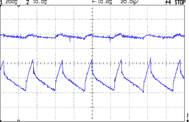
VG 1193 mV – ID 50 mA-div – 1 ms PWM filter Using 64 kHz PWM requires putting the timers in Fast PWM Mode:
- Timer 1: Mode 5 = Fast PWM, 8-bit resolution
- Timer 2: Mode 3
The Arduino code that does the deed:
// Timer 1: PWM 9 PWM 10 - Hall offset
TCCR1A = B10000001; // Mode 5 = fast 8-bit PWM with TOP=FF
TCCR1B = B00001001; // ... WGM, 1:1 clock scale -> 64 kHz

// Timer 2: PWM3 PWM11 - MOSFET gate drive A, B
TCCR2A = B10100011; // Mode 3 = fast PWM with TOP=FF
TCCR2B = B00000001; // ... 1:1 clock scale -> 64 kHz

analogWrite(PIN_SET_VGATE_A,0); // force gate voltage = 0
analogWrite(PIN_SET_VGATE_B,0);
With that in hand, things look a lot better:
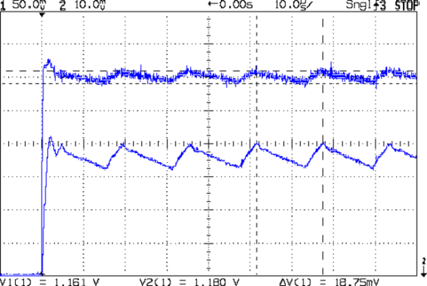
PWM Ripple – 64 kHz 200 mA The oscilloscope scales aren’t the same and the PWM duty cycle isn’t quite the same, but the LED current ripple drops by a little more than the factor of two you’d expect.
The crisp rising edge comes from the analog switch between the PWM filter and the MOSFET gate, plus a bit of code trickery that presets the PWM and lets it ramp up before turning on the gate drive.
I should recompute the voltage-to-current scale factor, but that could rapidly turn into a curve-fitting exercise. It’s pretty close already.


-
Subscribe
Subscribed
Have a WordPress.com account? Log in now.

