-
Kenmore 158: Motor RPM Sensor Deglitching
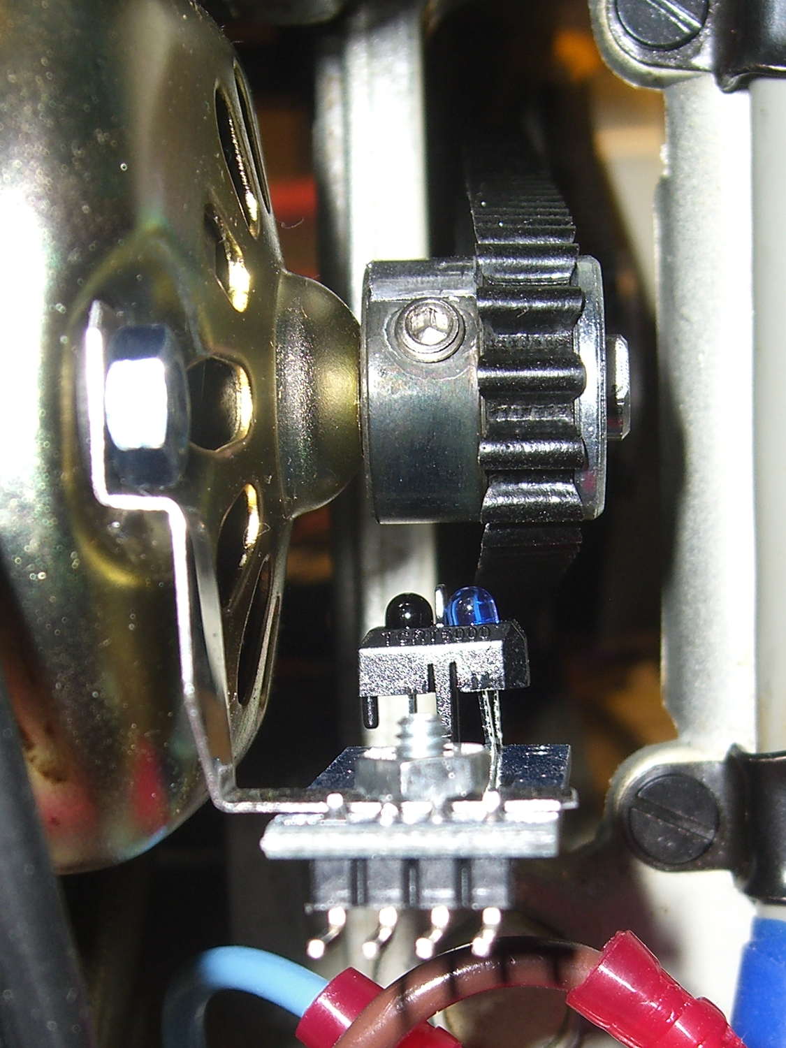
The setscrew in the motor pulley lies directly in the path of the photosensor:
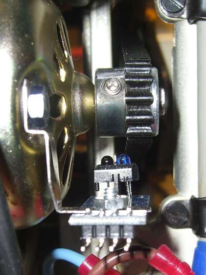
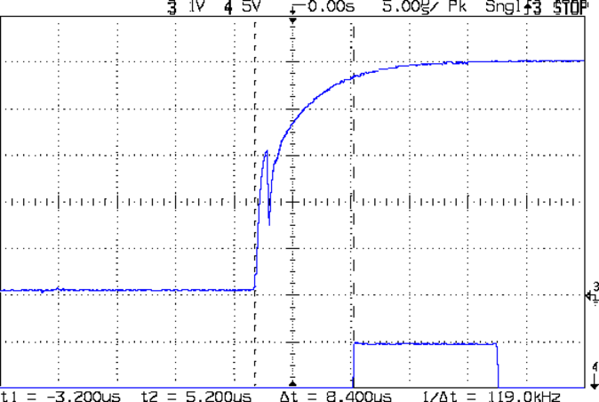
TCTR5000 Motor RPM Sensor – side view Which produces a glitch in the rising edge of the digital output as the pulley rotates from the dark to the light section:
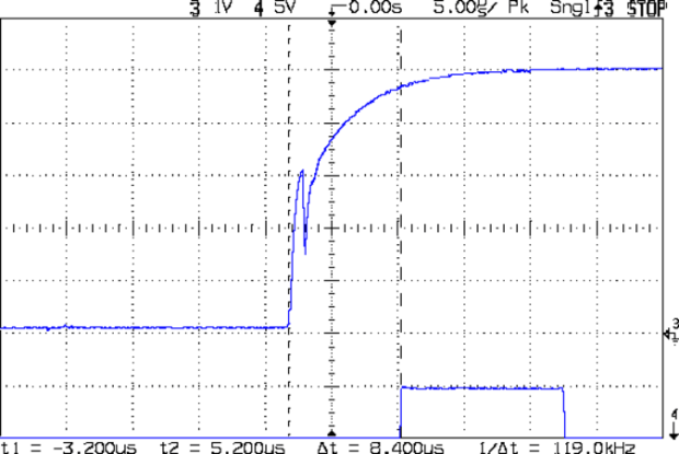
Motor Sensor – Rising Edge Glitch The RPM signal goes to Arduino pin
D2, where each falling edge triggers an interrupt handler:const byte PIN_MOTOR_REV = 2; // DI - IRQ 0 (must be D2) ... snippage... void setup() { ... snippage ... pinMode(PIN_MOTOR_REV,INPUT_PULLUP); attachInterrupt((PIN_MOTOR_REV - 2),ISR_Motor,FALLING); // one IRQ / motor revolution ... snippage ... }The maximum motor speed is about 11 kRPM, so interrupts should be at least 5.5 ms apart and the digital input should be low. If that’s true, then the code updates a bunch of useful information:
struct pulse_t {
 byte Counter;
 unsigned long TimeThen;
 unsigned long Period;
 word RPM;
 byte State;
};

struct pulse_t Motor;

... snippage ...

//------------------
// ISR to sample motor RPM sensor timing

void ISR_Motor(void) {

static unsigned long Now;

	digitalWrite(PIN_SYNC,HIGH);

	Now = micros();

	if ((5000ul < (Now - Motor.TimeThen)) && !digitalRead(PIN_MOTOR_REV) ) {	// discard glitches
		Motor.Counter++;
		Motor.Period = Now - Motor.TimeThen;
		Motor.TimeThen = Now;
		Motor.State = digitalRead(PIN_MOTOR_REV);		// always zero in a Physics 1 world
	}

	digitalWrite(PIN_SYNC,LOW);
	return;
}
The scope trace shows that the handler takes about 7 µs to get control after the glitch (the left cursor should be on the falling edge, not the rising edge), so the input read occurs when the sensor output is over 4.5 V, causing the handler to discard this spurious interrupt.
Because
Motor.Periodis a four-byteunsigned long, the Arduino’s CPU must handle it in chunks. Rather than disable interrupts around each use, it’s better to read the value until two successive copies come back identical://------------------ // Return current microsecond period without blocking ISR unsigned long ReadTime(struct pulse_t *pTime) { unsigned long Sample; do { Sample = pTime->Period; // get all four bytes } while (Sample != pTime->Period); // repeat until not changed by ISR while reading pTime->Counter = 0; // this is a slight race condition return Sample; }Because the interrupts don’t happen that often, the loop almost always executes only one time. On rare occasions, it’ll go back for another two values.
Converting the pulley rotation period into revolutions per minute goes like this:
Motor.RPM = 60000000ul/ReadTime(&Motor); // one (deglitched) pulse / rev
That’s easier than hiding the setscrew and it also discards any other glitches that may creep into
D2…
-
Subscribe
Subscribed
Have a WordPress.com account? Log in now.

