-
Laser-Cut Vole Trap Boxes
We deployed low-effort vole trap boxes a few weeks ago, only to discover no voles checked in, most likely due to wintertime gardens consisting of bare earth. I had weighted the boxes with convenient rocks that pretty much crushed them flat during rainstorms.
So I converted a few dozen square feet of cardboard into better-looking boxes and transferred the traps:
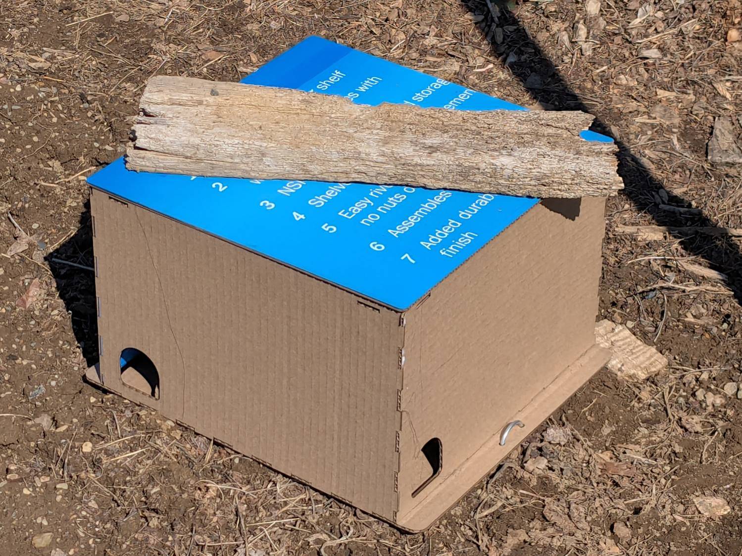
Vole Finger Box – large That one has a rat trap inside.
Smaller boxes hold mouse traps:
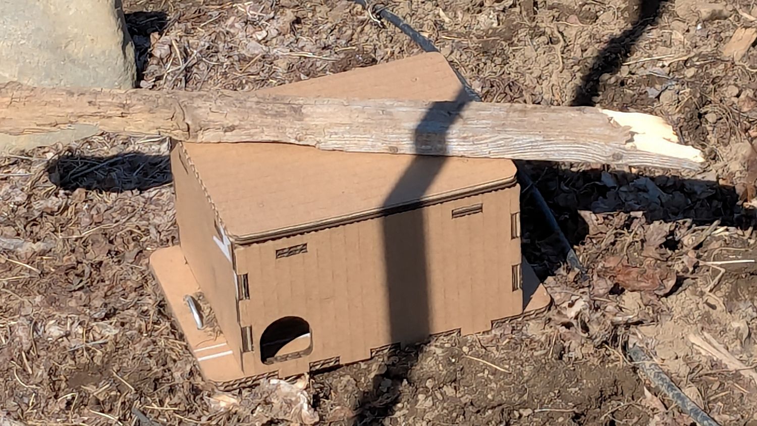
Vole Finger Box – small Two pairs of 4 mm holes on the bottom flanges fit some spare irrigation pipe holddowns to, yes, hold them down, with those rotten planks keeping their lids in place.
They’re lightly customized “Electronics Boxes” held together by hot-melt glue. The jawbreaker URLs will get you started:
Cardboard remains the wrong material, but my stockpile remains well-stocked.
-
Subscribe
Subscribed
Already have a WordPress.com account? Log in now.
