-
Mostly Printed CNC: Endstop Mount
Being a big fan of having a CNC machine know where it is, adding endstops (pronounded “home switches” in CNC parlance) to the Mostly Printed CNC axes seemed like a good idea:
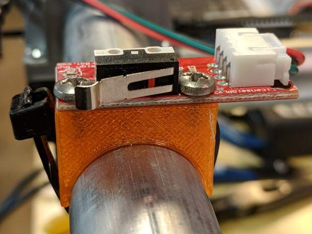
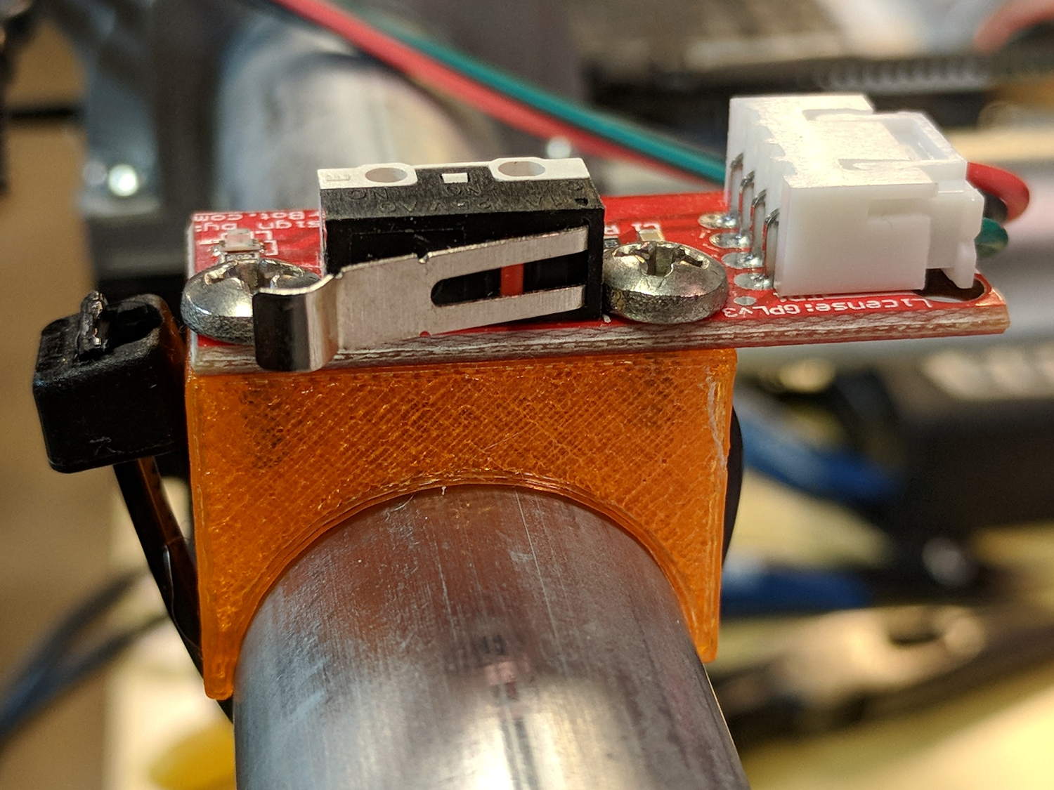
MPCNC – X min endstop – actuator view All the mounts I could find fit bare microswitches of various sizes or seemed overly complex & bulky for what they accomplished. Rather than fiddle with screws and nut traps / inserts, a simple cable tie works just fine and makes the whole affair much smaller. Should you think cable ties aren’t secure enough, a strip of double stick tape will assuage your doubts.
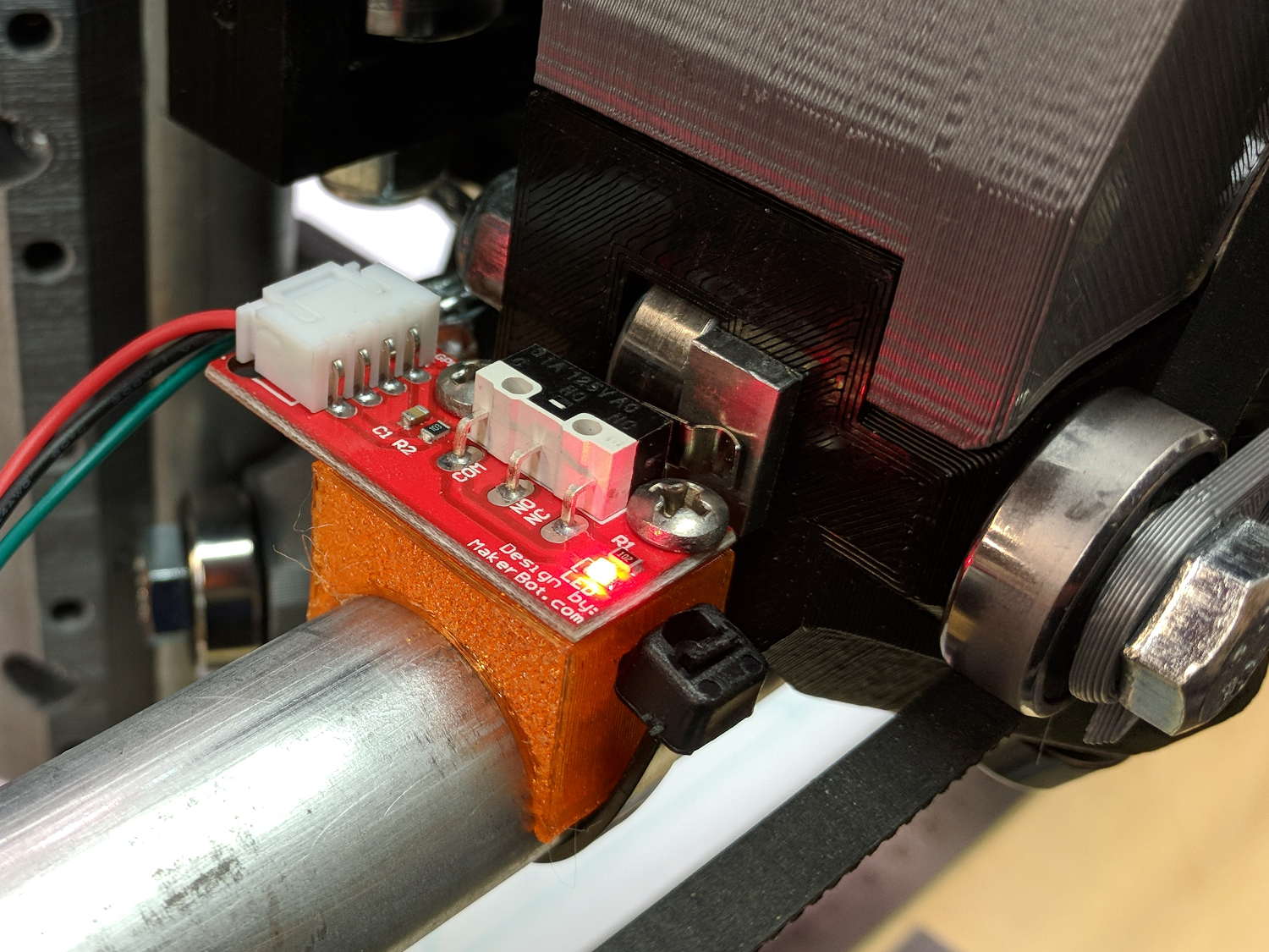
A snippet of aluminum sheet moves the switch trip point out beyond the roller’s ball bearing:
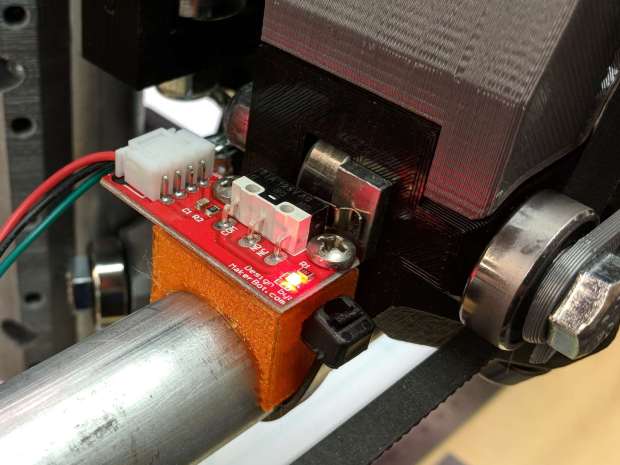
MPCNC – X min endstop I’m not convinced homing the Z axis at the bottom of its travel is the right thing to do, but it’s a start:
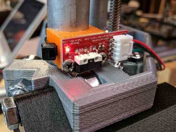
MPCNC – Z min endstop Unlike the stationary X and Y axes, the MPCNC’s Z axis rails move vertically in the middle block assembly; the switch moves downward on the rail until the actuator hits the block.
Perforce, the tooling mounted on the Z axis must stick out below the bottom of the tool carrier, which means the tool will hit the table before the switch hits the block. There should also be a probe input to support tool height setting.
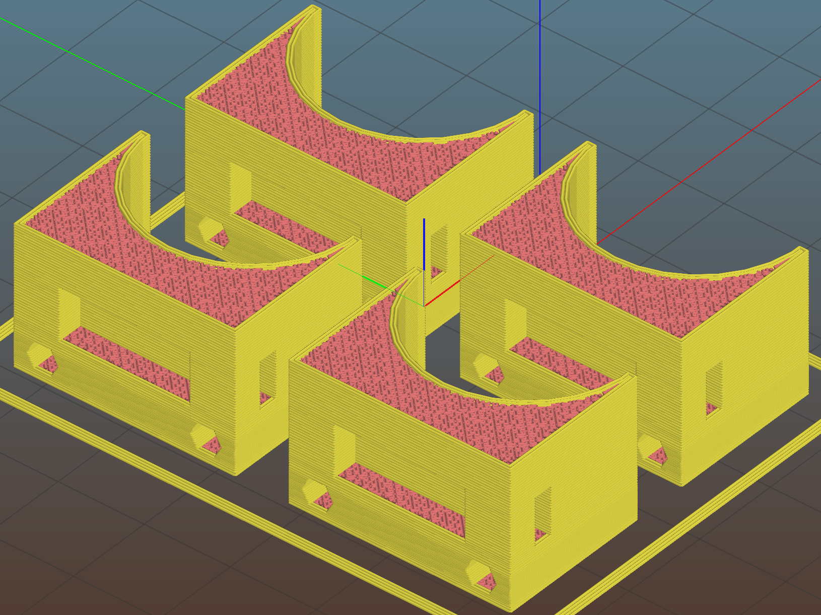
The first mount fit perfectly, so I printed four more in one pass:
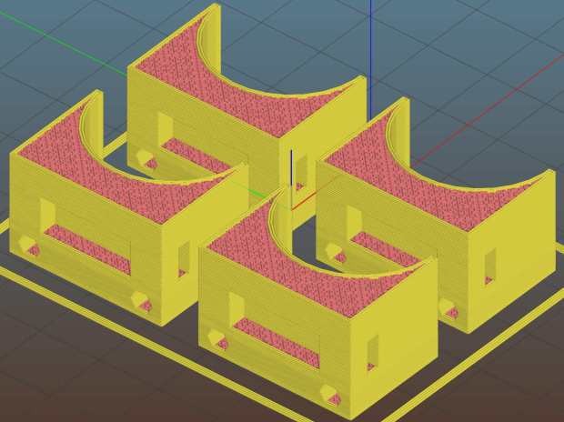
MPCNC MB Endstop Mounts – Slic3r preview All three endstops plug into the RAMPS board, leaving the maximum endstop connections vacant:
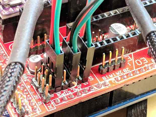
MPCNC – RAMPS min endstop positions Obviously, bare PCBs attached to the rails in mid-air aren’t compatible with milling metal, which I won’t be doing for quite a while. The electronic parts long to be inside enclosures with ventilation and maybe dust filtering, but …
The switches operate in normally open mode, closing when tripped. That’s backwards, of course, and defined to be completely irrelevant in the current context.
Seen from a high level, these switches set the absolute “machine coordinate system” origin, so the firmware travel limits can take effect. Marlin knows nothing about coordinate systems, but GRBL does: it can touch off to a fixture origin and generally do the right thing.
The OpenSCAD source code as a GitHub Gist:
This file contains hidden or bidirectional Unicode text that may be interpreted or compiled differently than what appears below. To review, open the file in an editor that reveals hidden Unicode characters. Learn more about bidirectional Unicode characters// Tour Easy Fairing Endstop Mount for Makerbot PCB // Ed Nisley KE4ZNU – 2017-11-07 /* [Build Options] */ Layout = "Build"; // [Build, Show, Block] Section = false; // show internal details /* [Extrusion] */ ThreadThick = 0.25; // [0.20, 0.25] ThreadWidth = 0.40; // [0.40] function IntegerMultiple(Size,Unit) = Unit * ceil(Size / Unit); /* [Hidden] */ Protrusion = 0.01; // [0.01, 0.1] HoleWindage = 0.2; ID = 0; OD = 1; LENGTH = 2; /* [Sizes] */ RailOD = 23.5; Screw = [3.4,6.8,8.0]; // thread dia, head OD, screw length HoleOffset = [2.5,19.0/2]; // PCB mounting holes from PCB edge, rail center SwitchClear = [6.0,15,3.0]; // clearance around switch pins SwitchOffset = [6.0,0]; // center of switch from holes Strap = [5.5,50,2.0]; // nylon strap securing block to rail Block = [16.4,26.0,RailOD/2 + SwitchClear[2] + Strap[2] + 6*ThreadThick]; // basic block shape //- Adjust hole diameter to make the size come out right module PolyCyl(Dia,Height,ForceSides=0) { // based on nophead's polyholes Sides = (ForceSides != 0) ? ForceSides : (ceil(Dia) + 2); FixDia = Dia / cos(180/Sides); cylinder(r=(FixDia + HoleWindage)/2,h=Height,$fn=Sides); } //- Shapes module PCBBlock() { difference() { cube(Block,center=true); translate([(SwitchOffset[0] + HoleOffset[0] – Block[0]/2),SwitchOffset[1],(Block[2] – SwitchClear[2] + Protrusion)/2]) cube(SwitchClear + [0,0,Protrusion],center=true); for (j=[-1,1]) translate([HoleOffset[0] – Block[0]/2,j*HoleOffset[1],(Block[2]/2 – Screw[LENGTH])]) rotate(180/6) if (false) // true = loose fit PolyCyl(Screw[ID],Screw[LENGTH] + Protrusion,6); else cylinder(d=Screw[ID],h=Screw[LENGTH] + Protrusion,$fn=6); translate([0,0,Block[2]/2 – SwitchClear[2] – Strap[2]/2 – 3*ThreadThick]) cube(Strap,center=true); if (Section) translate([Block[0]/2,0,0]) cube(Block + [0,2*Protrusion,2*Protrusion],center=true); } } module Mount() { difference() { translate([0,0,Block[2]/2]) PCBBlock(); rotate([0,90,0]) cylinder(d=RailOD,h=3*Block[0],center=true); } } //- Build things if (Layout == "Show") { Mount(); color("Yellow",0.5) rotate([0,90,0]) cylinder(d=RailOD,h=3*Block[0],center=true); } if (Layout == "Block") PCBBlock(); if (Layout == "Build") translate([0,0,Block[2]/2]) rotate([0,-90,0]) Mount();


-
Subscribe
Subscribed
Have a WordPress.com account? Log in now.

