-
MPCNC: Tweaked GRBL Config
These GRBL configuration constants seem to work well with the DW660 router in the MPCNC gantry:
This file contains hidden or bidirectional Unicode text that may be interpreted or compiled differently than what appears below. To review, open the file in an editor that reveals hidden Unicode characters. Learn more about bidirectional Unicode characters$$ $0=10 $1=255 $2=0 $3=2 $4=0 $5=0 $6=0 $10=1 $11=0.010 $12=0.002 $13=0 $20=1 $21=1 $22=1 $23=0 $24=500.000 $25=2500.000 $26=250 $27=3.000 $30=30000 $31=0 $32=0 $100=100.000 $101=100.000 $102=400.000 $110=8000.000 $111=8000.000 $112=3000.000 $120=2000.000 $121=2000.000 $122=2000.000 $130=635.000 $131=465.000 $132=103.000 —– $n $N0=F150 $N1=G10L2P1X-633Y-463Z-3 —– $# [G54:-633.000,-463.000,-3.000] [G55:0.000,0.000,0.000] [G56:0.000,0.000,0.000] [G57:0.000,0.000,0.000] [G58:0.000,0.000,0.000] [G59:0.000,0.000,0.000] [G28:-418.670,-282.016,-3.000] [G30:-628.000,-3.000,-3.000] [G92:0.000,0.000,0.000] [TLO:0.000] [PRB:0.000,0.000,0.000:0] The overall XY travel is slightly smaller than the initial configuration, because the router sticks out further than the penholder I’d been using. Increasing the
$27Homing Pulloff distance to 3 mm leaves a comfortable space beyond the limit switches after homing to the positive end: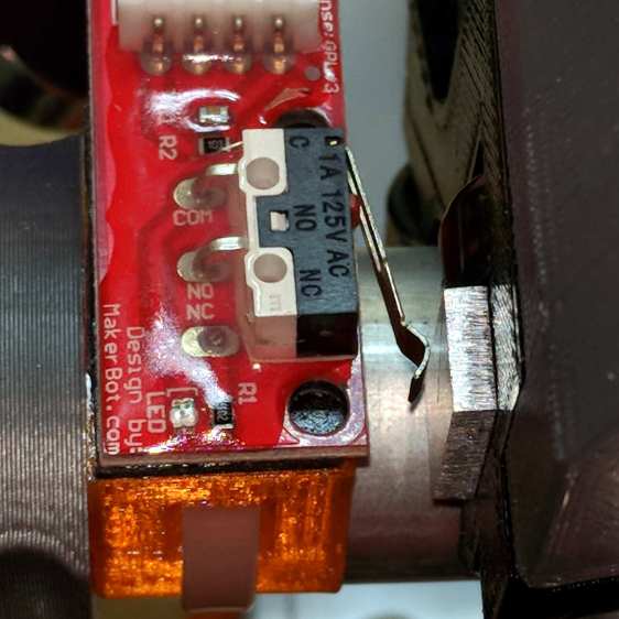
MPCNC – X-axis endstop – home Adjusting the
$13[01]XY travel distances and switch positions on the other end of the rail leaves a similar comfort zone at the negative end: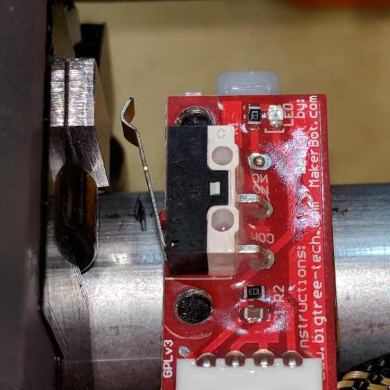
MPCNC – X-axis endstop – X min Both switches now live on the rear X-axis rail and appear as seen from behind the bench; they just look backwards. The Y-axis switches are on the left rail and look exactly the same.
The XY travel works out to 630 × 460 mm = 24.8 × 18.1 inch, which is Good Enough.
Some fiddling with the Z axis limit switch tape mask produces a nice round 100 mm = 3.9 inch vertical travel. The Z-axis rails just barely clear the table at the lower limit and just barely stay in the bottom bearings at the upper limit, so it’s a near thing. In practical terms, the rails or the tool will smash into the workpiece sitting atop the table before the limit switch trips.
Setting both
$20=1Soft Limits and$21=1Hard Limits may be excessive, but I vastly prefer having the firmware detect out-of-range moves and the hardware forcibly shut down if the firmware loses track of its position, rather than letting it grind away until I can slap the BRS. The steppers aren’t powerful enough to damage anything, of course, so it’s a matter of principle.The
$N0=F150sets the initial speed, as the defaultF0seems to (sometimes) confuse bCNC’s auto-level grid probing.The
$N1=G10L2P1X-633Y-463Z-3sets the defaultG54coordinate origin to the front-left corner, withZ=0at the home position up top, so as to prevent surprises. I expect to useG55for most work holder touchoffs, although we’ll see how that plays out.The
G28andG30settings depend on the tool change location and the Z-axis probe location, so they’re still not cast in concrete.

-
Subscribe
Subscribed
Have a WordPress.com account? Log in now.

